PCoIP Proxy – NetScaler Gateway 12 / Citrix Gateway 12.1

Last Modified: Dec 22, 2018 @ 8:47 am

Navigation

Change Log

  • 2018 Dec 22 – renamed NetScaler Gateway to Citrix Gateway
  • 2018 Oct 7 – updated screenshots for Citrix Gateway 12.1

Overview

NetScaler Gateway 12.0 and Citrix Gateway 12.1 and newer support the PC-over-IP (PCoIP) protocol, which is the remote display protocol for several non-Citrix VDI solutions, including VMware Horizon. PCoIP is analogous to Citrix HDX/ICA protocol, and Microsoft RDP protocol. PCoIP uses UDP port 4172.

  • VMware Blast is currently not supported

When PCoIP is proxied through Citrix Gateway, Citrix Gateway can replace the traditional PCoIP remote access solutions, like Horizon Security Server, or VMware Unified Access Gateway.

Prerequisites

  • NetScaler Version – NetScaler 12.0 or newer.
    • Build 51 and newer for NAT
  • NetScaler Edition – PCoIP Proxy is available in all NetScaler Editions
  • Universal Licenses – PCoIP Proxy uses the Clientless Access feature of Citrix Gateway, which means every Citrix Gateway connection must be licensed for Citrix Gateway Universal. On the Citrix Gateway Virtual Server, ensure ICA Only is unchecked.
  • Horizon infrastructure – A functioning internal Horizon infrastructure. Ensure you can connect to Horizon Agents internally without Citrix Gateway.
    • Ensure that the Horizon HTTP(S) Secure Tunnel and PCoIP Secure Gateway are not enabled on the Horizon Connection Servers that NetScaler will proxy connections to.
    • Configure Desktop Pools and RDS Farms to use PCoIP as the default protocol.
  • Firewall Ports:
    • TCP 4172, UDP 4172, and TCP 443 open from Horizon Clients to the Citrix Gateway VIP.
    • TCP 4172, and UDP 4172 open from the NetScaler SNIP to all internal Horizon Agents.
  • Certificate – A valid certificate for the Citrix Gateway Virtual Server.
  • Authentication – An LDAP authentication policy/server.
  • Unified Gateway (optional) – If Unified Gateway, create the Unified Gateway before adding PCoIP functionality.
  • RfWebUI Portal Theme – For web browser access to Horizon, the Citrix Gateway Virtual Server must be configured with the RfWebUI theme.
  • Horizon Client – The Horizon Client must be installed on the client device, even if accessing Horizon published icons using the NetScaler RfWebUI portal.

PCoIP Profile

To create the PCoIP Profile:

  1. In the NetScaler management GUI, navigate to Citrix Gateway > Policies> PCoIP.
  2. On the right, in the PCoIP Profiles and Connections pane, you will create a VServer profile and a PCoIP profile.
  3. To create a VServer profile, on the VServer Profiles tab, click Add.

    1. Enter a name for the VServer profile. The only purpose of the VServer Profile is to specify the Active Directory domain name so name it accordingly.
    2. Enter an Active Directory Domain Name that will be used for Single Sign-on to Horizon Connection Server, and then click Create.
    3. Note: only a single Active Directory domain is supported per NetScaler Gateway Virtual Server. Also, the domain name specified here is displayed in the Horizon Client.
  4. To create a PCoIP profile, on the Profiles tab, click Add.

    1. Enter a name for the PCoIP Profile. The PCoIP Profile specifies the internal DNS name for Horizon so name it accordingly.
    2. Enter the internal connection URL for the internal VMware Horizon View Connection Servers, and then click Create. NetScaler SNIP needs to be able to connect to this URL.

Session Policy/Profile

To create or edit a Session Policy/Profile that has PCoIP Proxy enabled:

  1. Navigate to  Citrix Gateway > Policies> Session.
  2. On the right, select the Session Profiles tab.
  3. On the NetScaler Gateway Session Policies and Profiles page, create or edit a NetScaler Gateway Session Profile.
    1. To create a NetScaler Gateway session profile, click Add, and provide a name.
    2. To edit a NetScaler Gateway session profile, select the profile, and click Edit.
  4. On the Client Experience tab, ensure that the Clientless Access value is set to On.
  5. On the Security tab, ensure that the Default Authorization Action value is set to ALLOW.
  6. On the PCoIP tab, select the required PCoIP profile. Note: you can also create or edit PCoIP Profiles from this tab.
  7. Click Create or OK to finish creating or editing the Session Profile.
  8. If you created a new Session Profile, then you must also create a corresponding Session Policy.
    1. Navigate to Configuration > Citrix Gateway > Policies > Session.
    2. On the right, select the Session Policies tab.
    3. Click Add.
    4. Provide a name for the Session Policy, and select the required session profile name from the Profile drop-down.
    5. In the Expression area, type true (Default Syntax, or Advanced Policy), and then click Create.

Gateway Virtual Server

Bind the created PCoIP VServer profile and Session Policy to a Citrix Gateway Virtual Server:

  1. Go to Citrix Gateway > Virtual Servers.
  2. On the right, either Add a new Citrix Gateway Virtual Server, or Edit an existing Citrix Gateway Virtual Server.
  3. If you are editing an existing Citrix Gateway Virtual Server, in the Basic Settings section, click the pencil icon.
  4. For both adding and editing, in the Basic Settings section, click More.
  5. Use the PCoIP VServer Profile drop-down to select the required PCoIP VServer Profile.
  6. Scroll down and ensure that ICA Only is unchecked. Then click OK to close the Basic Settings section.
  7. If you are creating a new Citrix Gateway Virtual Server, bind a certificate, and bind an LDAP authentication policy.
  8. Then scroll down to the Policies section and click the plus icon.
  9. The Choose Type page defaults to Session and Request. Click Continue.
  10. In the Policy Binding section, click on Click to select.
  11. Click the radio button next to the required Session Policy that has the PCoIP Profile configured, and then click the blue Select button at the top of the window.
  12. Back in the Policy Binding page, click Bind.
  13. If you want to use a web browser to connect to VMware Horizon, then on the right, under Advanced Settings, add the Portal Themes section. If you are only using Horizon Client to connect to Citrix Gateway, then you don’t need to perform this step.

    1. Use the Portal Theme drop-down to select RfWebUI, and click OK.
    2. Horizon published icons are added to the RfWebUI portal.
  14. To enable support for NAT, SSH to the NetScaler to access the CLI.
    1. Run the command set vpn vserver MyVserverName -vserverFqdn MyFQDN. This causes NetScaler to send the FQDN back to the Horizon Client, which enables it to connect to the public IP instead of the DMZ private IP address. Unfortunately, this setting is not available in the NetScaler GUI.

Horizon Configuration

  1. In Horizon Administrator, go to View Configuration > Servers. Edit the Horizon Connection Server that Citrix Gateway connects to.

    1. On the General tab, uncheck PCoIP Secure Gateway.
    2. In Citrix Gateway 12.1 build 49 and newer, to enable USB Redirection, enable the HTTP(S) Secure Tunnel and enter the external FQDN for Citrix Gateway.
    3. Click OK when done.
  2. At Resources > Farms, edit your RDS Farms.

    1. Set the Default display protocol to PCoIP.

Update Content Switching Expression for Unified Gateway

If your Citrix Gateway Virtual Server is behind a Unified Gateway (Content Switching Virtual Server), then you must update the Content Switching Expression to include the PCoIP URL paths.

  1. In the NetScaler GUI, navigate to Configuration> Traffic Management > Content Switching > Policies.
  2. On the right, select the Unified Gateway Content Switching Policy, and then click Edit.
  3. Append the following expression under the Expression area, and then click OK.
    || http.req.url.path.eq("/broker/xml") || http.req.url.path.eq("/broker/resources") || http.req.url.path.eq("/pcoip-client")

Use Citrix Gateway PCoIP Proxy

  1. To connect, you must have Horizon View Client installed on the client device. Once installed, you can either use the Horizon View Client’s User Interface to connect to Citrix Gateway, or you can use the Citrix Gateway RfWebUI portal page to view the icons published from Horizon.
  2. To view the active PCoIP connections, in NetScaler, go to Citrix Gateway > Policies > PCoIP.
  3. On the right, switch to the Connections tab. The active sessions are displayed with the following data: user name, Horizon View Client IP, and Horizon View Agent Destination IP.
  4. To terminate a connection, right-click the connection, and click Kill Connection. Or click Kill All Connnections to terminate all PCoIP connections.

CLI Commands

Here are CLI Commands for the configuration shown above.

add ssl certKey WildcardCorpCom -cert WildcardCorpCom.pfx -key WildcardCorpCom.pfx -inform PFX -passcrypt "abc"

add authentication ldapAction AD01 -serverIP 10.2.2.11 -serverPort 636 -ldapBase "dc=corp,dc=local" -ldapBindDn ctxsvc@corp.local -ldapBindDnPassword abc -encrypted -encryptmethod ENCMTHD_3 -ldapLoginName sAMAccountName -groupAttrName memberOf -subAttributeName cn -secType SSL
add authentication ldapPolicy AD01 ns_true AD01

add vpn pcoipVserverProfile corp -loginDomain corp
add vpn pcoipProfile vcs01 -conServerUrl "https://vcs01.corp.local"

add vpn sessionAction VPN -defaultAuthorizationAction ALLOW -clientlessVpnMode ON -pcoipProfileName vcs01
add vpn sessionPolicy VPN true VPN

add vpn vserver VPN SSL 10.3.3.13 443 -downStateFlush DISABLED -Listenpolicy NONE -vserverFqdn vpn.corp.com -pcoipVserverProfileName corp

bind vpn vserver VPN -portaltheme RfWebUI
bind vpn vserver VPN -policy AD01 -priority 100
bind vpn vserver VPN -policy VPN -priority 100 -gotoPriorityExpression NEXT -type REQUEST -urlName RDP
bind ssl vserver VPN -certkeyName WildcardCorpCom

Native One Time Passwords (OTP) – NetScaler Gateway 12 / Citrix Gateway 12.1

Last Modified: Feb 28, 2019 @ 1:09 pm

Navigation

Change Log

Overview

NetScaler 12 Native OTP lets you enable two-factor authentication without purchasing any other authentication product. A typical configuration uses Google Authenticator to generate Passcodes. See the following for an overview:

Here are some notes:

  • NetScaler Native OTP is part of nFactor, and thus requires Citrix ADC Advanced Edition (aka NetScaler Enterprise Edition) or Citrix ADC Premium Edition (aka NetScaler Platinum Edition) licensing. NetScaler ADC Standard Edition licensing is not sufficient.
  • Workspace app 1809 and newer with Citrix Gateway (NetScaler) 12.1 build 49 and newer support nFactor authentication. Older Receivers and older NetScalers don’t support it, so you’ll instead have to use a web browser.  💡
  • Citrix Gateway VPN Plug-in 12.1 build 49 and later support nFactor when authenticating using the VPN Plug-in.  💡
  • nFactor requires a AAA vServer, which can be non-addressable – you don’t need any additional public IPs.
  • OTP stores device enrollment secrets in an Active Directory attribute that accepts Strings. Citrix’s documentation uses the userParameters Active Directory attribute.
    • The LDAP bind account must have permission to modify this attribute on every user.
  • Users can enroll multiple devices. There’s no way to prevent this.
  • The manageotp website is usually only protected by single factor authentication. Since users can add multiple devices, the manageotp website must be protected from external access.
  • Christian in the comments indicated that Microsoft Authenticator also works. Click on plus sign -> other (Google,…).

Here are the OTP configuration objects:

  • Make sure NTP is configured on the NetScaler. Accurate time is required.
  • An LDAP Policy/Server with authentication disabled and OTP Secret configured. This one OTP-specific LDAP Policy/Server can be used for two scenarios:
    • manageotp device enrollment
    • Two-factor authentication to NetScaler Gateway after a device has been enrolled. This LDAP Policy/Server verifies the entered passcode.
  • An LDAP Policy/Server with authentication enabled. This one policy is used for two scenarios:
    • Single-factor authentication to the manageotp authenticator/device enrollment website.
    • Two-factor authentication to NetScaler Gateway after a device has been enrolled.
  • A single non-addressable AAA vServer with two Login Schemas for the following scenarios:
    • A single-factor Login Schema for manageotp.
    • A dual-factor Login Schema for NetScaler Gateway authentication.
  • An Authentication Profile to link the AAA vServer to the NetScaler Gateway vServer.

LDAP Policies/Actions

  1. Go to Security > AAA – Application Traffic > Polices > Authentication > Advanced Policies > Actions > LDAP.
  2. On the right, click Add.

    1. Create a normal LDAP Server if you don’t have one already. This one has Authentication enabled. This LDAP Policy/Server will be used for single-factor authentication to the manageotp website, and for first factor of dual-factor authentication to NetScaler Gateway (second factor is OTP). There are no special instructions for this LDAP Server.
  3. Create another LDAP Action.

    1. This one is used by the manageotp site to set the OTP authenticator in Active Directory, so name it accordingly.
    2. On the right, uncheck the box next to Authentication. If you don’t uncheck it, you will see an error message after configuring the OTP Secret.
    3. Make sure the Administrator Bind DN has permissions to modify the OTP Secret Active Directory attribute for all users.
    4. If you cloned an existing LDAP Server, then make sure you re-enter the Administrator Password or the new one won’t work. Then click Test LDAP Reachability.
    5. Configure the Server Logon Name Attribute to match the one you configured in the normal authentication LDAP Server.
    6. In the Other Settings section, on the bottom right, find the OTP Secret field. Enter the name of the Active Directory attribute where NetScaler will store the user’s OTP secret. You can use the userParameters attribute if that attribute isn’t being used for anything else.
    7. Thomas Rolfs in the comments advises not to enable Nested Group Extraction in this LDAP Action.
    8. Click Create when done.
  4. Create another LDAP Action.
    1. This one will verify the OTP code entered by the user, so name it accordingly. The only difference from the prior one is the addition of an LDAP Search Filter.
    2. On the right, uncheck the box next to Authentication. If you don’t uncheck it, you will see an error message after configuring the OTP Secret.
    3. Make sure the Administrator Bind DN has permissions to read the OTP Secret Active Directory attribute.
    4. If you cloned an existing LDAP Server, then make sure you re-enter the Administrator Password or the new one won’t work.
    5. In the Other Settings section, configure the Server Logon Name Attribute to match the one you configured in the normal authentication LDAP Server.
    6. In the Search Filter field, enter the text userParameters>=#@. This syntax ensures that only users with enrolled authenticators can login. See George Spiers NetScaler native OTP for more info.
    7. In the Other Settings section, on the bottom right, find the OTP Secret field. Enter the name of the Active Directory attribute containing the user’s OTP secret.
    8. Click Create when done.
  5. Go to Security > AAA – Application Traffic > Policies > Authentication > Advanced Policies > Policy.
  6. On the right, click Add.

    1. You probably don’t already have an Advanced Authentication Policy for your normal LDAP server.
    2. Change the Action Type to LDAP.
    3. Select your normal LDAP server, which is the one that has Authentication enabled.
    4. Enter true as the expression. This uses Default Syntax instead of Classic Syntax.
    5. Click Create.
  7. Create another Authentication Policy.

    1. This policy is for OTP management so name it accordingly.
    2. Change the Action Type to LDAP.
    3. Select the Set OTP LDAP Server that has Authentication disabled and OTP Secret configured. This LDAP Action should not have the Search Filter configured.
    4. Enter HTTP.REQ.COOKIE.VALUE(“NSC_TASS”).EQ(“manageotp”) in the Expression box, and click Create.
  8. Create another Authentication Policy.

    1. This policy is for OTP verification so name it accordingly.
    2. Change the Action Type to LDAP.
    3. Select the OTP Verification LDAP Server that has Authentication disabled and OTP Secret configured. This LDAP Action should have the Search Filter configured to prevent unenrolled users from authenticating.
    4. Enter true in the Expression box, and click Create.

Login Schemas

  1. Go to Security > AAA – Application Traffic > Login Schema.
  2. On the right, switch to the Profiles tab, and click Add.

    1. This is the single factor Login Schema for manageotp so name the Schema accordingly.
    2. Click the Edit icon.
    3. On the left, click the LoginSchema folder to open it.
    4. Scroll down, and click SingleAuthManageOTP.xml to highlight it.
    5. On the top right, click Select.
    6. Click Create.
  3. Add another Login Schema profile.

    1. This Login Schema is for two-factor authentication to NetScaler Gateway so name it accordingly.
    2. Click the edit icon. Follow the same procedure as above, but this time select /LoginSchema/DualAuth.xml.
    3. Click More to reveal more options.
    4. Scroll down. In the Password Credential Index field, enter 1. This causes nFactor to save the user’s password into AAA Attribute #1, which we’ll use later in a Traffic Policy to Single Sign-on to StoreFront. If you don’t do this, then NetScaler Gateway will try to use the Passcode to authenticate to StoreFront, which obviously won’t work.
    5. Check the box next to Enable Single Sign On Credentials. Mark in the comments indicates that this checkbox is needed to Single Sign On to RDP Hosts.
    6. Click Create.
  4. On the right, switch to the Policies tab.
  5. Click Add to add a Login Schema policy.
    1. In the Profile field, select the Single Factor Manage OTP Login Schema Profile.
    2. Name the Login Schema Policy for OTP management.
    3. In the Rule field, enter the following. This ensures that this single factor Login Schema is only used if the user enters /manageotp, and if the user is on the internal network. You don’t want manageotp to be accessible externally, because it’s only protected by single factor authentication, and it’s too easy to add multiple devices.
      http.req.cookie.value("NSC_TASS").eq("manageotp") && client.IP.SRC.IN_SUBNET(10.2.0.0/16)
    4. Click Create.
  6. Create another Login Schema Policy.

    1. In the Profile field, select the dual factor Login Schema.
    2. Name the Login Schema to indicate dual factor authentication.
    3. In the Rule box, enter true.
    4. Click Create.

Authentication PolicyLabel

  1. Go to Security > AAA – Application Traffic > Policies > Authentication > Advanced Policies > PolicyLabel.
  2. On the right, click Add.
  3. This PolicyLabel is for OTP management, and OTP verification, so name it accordingly.
  4. In the Login Schema field, select LSCHEMA_INT, which means noschema.
  5. Click Continue.
  6. In the Policy Binding section, Click to select.
  7. Click the radio button button next to the Manage OTP LDAP Policy that has authentication disabled, and OTP Secret configured. This one should have a policy expression that limits it to manageotp only. Click Select.
  8. Click Bind.
  9. Click Add Binding to add another one.
  10. Click to select.
  11. Click the radio button next to the LDAP Policy that verifies OTP. Click Select.
  12. Click Bind.
  13. Make sure the manageotp policy is higher in the list than the OTP Verification policy. To adjust priorities, right-click on the policies, and click Edit Binding. Click Done.

AAA vServer

  1. Go to Security > AAA – Application Traffic.
    1. If the AAA feature is not enabled, then right-click the AAA node, and click Enable Feature.
  2. Go to Security > AAA – Application Traffic > Virtual Servers.
  3. On the right, click Add.
  4. This AAA vServer is for OTP so name it accordingly.
  5. Change the IP Address Type to Non Addressable.
  6. Click OK.
  7. Click where it says No Server Certificate.

    1. In the Server Certificate Binding section, click Click to select.
    2. Click the radio button next to a certificate, and click Select. You can use the same certificate as NetScaler Gateway.
    3. Click Bind.
  8. Click Continue to close the Certificate section.
  9. In the Advanced Authentication Policies section, click where it says No Authentication Policy.

    1. Click where it says Click to select.
    2. Click the radio button next to the normal LDAP Policy that has authentication enabled. Then click the blue Select button.
    3. In the Select Next Factor field, click where it says Click to select.
    4. Click the radio button next to the OTP PolicyLabel, and click Select.
    5. Click Bind.
  10. In the Advanced Authentication Policies section, click Continue.
  11. On the right, in the Advanced Settings column, click Login Schemas.
  12. On the left, scroll down, and click where it says No Login Schema.

    1. Click where it says Click to select.
    2. Click the radio button next to the Manage OTP Login Schema, and click Select.
    3. Click Bind.
  13. Click where it says 1 Login Schema.

    1. Click Add Binding.
    2. Click where it says Click to select.
    3. Click the radio button next to the dual factor Login Schema, and click Select.
    4. Click Bind.
    5. Make sure the single factor Manage OTP Login Schema is higher in the list (lower priority number) than the dual factor Login Schema. Click Close.
  14. On the right, in the Advanced Settings column, click Portal Themes.
  15. On the left, scroll down, select RfWebUI as the Portal Theme, and click OK.
  16. Click Done.

Traffic Policy for Single Sign-on

  1. On the left, go to NetScaler Gateway > Policies > Traffic.
  2. On the right, switch to the Traffic Profiles tab, and click Add.
  3. This Traffic Profile is for OTP and/or nFactor. Name it accordingly.
  4. Scroll down.
  5. In the SSO Password Expression box, enter the following. This is where we use the Login Schema Password Attribute specified earlier.
    http.REQ.USER.ATTRIBUTE(1)
  6. Click Create.
  7. On the right, switch to the Traffic Policies tab, and click Add.
  8. In the Request Profile field, select the Traffic Profile you just created.
  9. Name the Traffic Policy.
  10. In the Expression box, enter true (Default Syntax).
    • If your NetScaler Gateway Virtual Server allows full VPN, change the expression to the following. Source = Julien Mooren at NetScaler – Native OTP is breaking SSL VPN.
      http.req.method.eq(post)||http.req.method.eq(get) && false
  11. Click Create.

NetScaler Gateway and Authentication Profile

  1. Go to NetScaler Gateway > Virtual Servers.
  2. Edit an existing Gateway vServer. If you don’t have one, see the other NetScaler Gateway topics on this site.
  3. Scroll down to the Policies section, and click the plus icon.
  4. Change the Choose Policy drop-down to Traffic, and click Continue.
  5. Click to select.
  6. Click the radio button next to the Traffic Policy you created earlier, and click Select.
  7. Click Bind.
  8. On the right, in the Advanced Settings column, click Authentication Profile.
  9. On the left, scroll down to the Authentication Profile section.
  10. Click Add to create one.
  11. Authentication Profile links the NetScaler Gateway vServer with the OTP AAA vServer, so name it accordingly.
  12. In the Authentication Virtual Server section, Click to select.
  13. Click the radio button next to the OTP AAA vServer, and click Select.
  14. Click Create.
  15. Scroll down again to the Authentication Profile section, and click OK.
  16. The Portal Theme bound to the Gateway vServer should be RfWebUI, or a derivative.
  17. Go to System > Profiles.
  18. On the right, switch to the SSL Profile tab.
  19. Edit the ns_default_ssl_profile_frontend profile.
  20. Make sure HSTS is not enabled in the profile, or RfWebUI, and manageotp won’t work correctly. This is probably a bug. Note: the Rewrite method of enabling HSTS should work.

Update Content Switching Expression for Unified Gateway

If your NetScaler Gateway Virtual Server is behind a Unified Gateway (Content Switching Virtual Server), then you must update the Content Switching Expression to include the manageotp paths.

  1. In the NetScaler GUI, navigate to ConfigurationTraffic Management > Content Switching > Policies.
  2. On the right, select the Unified Gateway Content Switching Policy, and then click Edit.
  3. Append the following expression under the Expression area, and then click OK.
    || HTTP.REQ.URL.CONTAINS("/manageotp")

Manageotp

  1. Point your browser to https://mygateway.corp.com/manageotp or similar. Simply add /manageotp to the end of your Gateway URL.
  2. Notice it’s only single-factor authentication. Login using normal LDAP credentials.
  3. Click Add Device.
  4. Enter a device name, and click Go.
  5. Launch the Google Authenticator application on your phone. Click the plus icon in Google Authenticator, and scan the QRCode that is shown on the screen.
  6. Christian in the comments indicated that Microsoft Authenticator also works. Click on plus sign -> other (Google,…).
  7. Click Test.
  8. Enter the passcode shown in your Authenticator, and click Go.
  9. If you logoff of manageotp, and access your Gateway URL normally, you’ll be prompted for two-factor authentication. Use the passcodes shown in your Google Authenticator application.
  10. It should Single Sign-on into StoreFront.

CLI Commands

Here’s a complete CLI configuration.

add ssl certKey WildcardCorpCom -cert WildcardCorpCom.pfx -key WildcardCorpCom.pfx -inform PFX -passcrypt "abc"
add authentication ldapAction LDAP-Corp -serverIP 10.2.2.11 -serverPort 636 -ldapBase "dc=corp,dc=local" -ldapBindDn ctxsvc@corp.local -ldapBindDnPassword abc -encrypted -encryptmethod ENCMTHD_3 -ldapLoginName sAMAccountName -groupAttrName memberOf -subAttributeName cn -secType SSL -passwdChange ENABLED -Attribute2 userParameters
add authentication ldapAction LDAP_OTP_set_no_auth -serverIP 10.2.2.11 -serverPort 636 -ldapBase "dc=corp,dc=local" -ldapBindDn admin@corp.local -ldapBindDnPassword abc -encrypted -encryptmethod ENCMTHD_3 -ldapLoginName sAMAccountName -groupAttrName memberOf -subAttributeName cn -secType SSL -authentication DISABLED -OTPSecret UserParameters
add authentication ldapAction LDAP_OTP_verify_no_auth -serverIP 10.2.2.11 -serverPort 636 -ldapBase "dc=corp,dc=local" -ldapBindDn admin@corp.local -ldapBindDnPassword abc -encrypted -encryptmethod ENCMTHD_3 -ldapLoginName sAMAccountName -searchFilter "userParameters>=#@" -groupAttrName memberOf -subAttributeName cn -secType SSL -authentication DISABLED -OTPSecret UserParameters
add authentication Policy Corp-Adv -rule true -action LDAP-Corp
add authentication Policy LDAP_Manage_OTP-pol -rule "HTTP.REQ.COOKIE.VALUE(\"NSC_TASS\").EQ(\"manageotp\")" -action LDAP_OTP_set_no_auth
add authentication Policy LDAP_Confirm_OTP-pol -rule true -action LDAP_OTP_verify_no_auth

add authentication loginSchema Dual_OTP-lschema -authenticationSchema "/nsconfig/loginschema/LoginSchema/DualAuth.xml" -passwordCredentialIndex 1
add authentication loginSchema Single_Manage_OTP-lschema -authenticationSchema "/nsconfig/loginschema/LoginSchema/SingleAuthManageOTP.xml"
add authentication loginSchemaPolicy Single_Manage_OTP-lschemapol -rule "http.req.cookie.value(\"NSC_TASS\").eq(\"manageotp\") && client.IP.SRC.IN_SUBNET(10.3.0.0/16)" -action Single_Manage_OTP-lschema
add authentication loginSchemaPolicy Dual_OTP-lschemapol -rule true -action Dual_OTP-lschema

add authentication policylabel OTP_pollabel -loginSchema LSCHEMA_INT
bind authentication policylabel OTP_pollabel -policyName LDAP_Manage_OTP-pol -priority 100 -gotoPriorityExpression NEXT
bind authentication policylabel OTP_pollabel -policyName LDAP_Confirm_OTP-pol -priority 110 -gotoPriorityExpression NEXT 

add authentication vserver OTP-AAA SSL 0.0.0.0
bind ssl vserver OTP-AAA -certkeyName WildcardCorpCom

bind authentication vserver OTP-AAA -portaltheme RfWebUI
bind authentication vserver OTP-AAA -policy Single_Manage_OTP-lschemapol -priority 100 -gotoPriorityExpression END
bind authentication vserver OTP-AAA -policy Dual_OTP-lschemapol -priority 110 -gotoPriorityExpression END
bind authentication vserver OTP-AAA -policy Corp-Adv -priority 100 -nextFactor OTP_pollabel -gotoPriorityExpression NEXT

add vpn trafficAction OTP-trafficprofile http -passwdExpression "http.REQ.USER.ATTRIBUTE(1)"
add vpn trafficPolicy OTP-trafficpol true OTP-trafficprofile

add authentication authnProfile OTP-authnprofile -authnVsName OTP-AAA

add vpn vserver Gateway.corp.com SSL 10.2.5.220 443 -downStateFlush DISABLED -Listenpolicy NONE -authnProfile OTP-authnprofile
set ssl vserver Gateway.corp.com -sslProfile ns_default_ssl_profile_frontend
add vpn sessionAction "Receiver For Web" -transparentInterception OFF -defaultAuthorizationAction ALLOW -SSO ON -icaProxy ON -wihome "https://storefront2.corp.com/Citrix/StoreWeb" -ntDomain corp.local -clientlessVpnMode OFF -storefronturl "https://storefront2.corp.com"
add vpn sessionPolicy "Receiver For Web" "HTTP.REQ.HEADER(\"User-Agent\").CONTAINS(\"CitrixReceiver\").NOT" "Receiver For Web"
bind vpn vserver Gateway.corp.com -portaltheme RfWebUI
bind vpn vserver Gateway.corp.com -policy "Receiver For Web" -priority 100 -gotoPriorityExpression NEXT -type REQUEST
bind vpn vserver Gateway.corp.com -policy OTP-trafficpol -priority 100 -gotoPriorityExpression END -type REQUEST
bind ssl vserver Gateway.corp.com -certkeyName WildcardCorpCom

Citrix ADC Fundamental Concepts: Part 2 – Certificates/SSL, Authentication, HTTP, VPN Networking, PXE, GSLB

Last Modified: Jan 9, 2021 @ 7:00 am

Navigation

💡 = Recently Updated

Change Log

  • 2018 Dec 26 – complete proofread, revised, and expanded
  • 2018 Dec 24 – renamed NetScaler to Citrix ADC

Citrix ADC is NetScaler

Citrix renamed their NetScaler product to Citrix ADC. ADC is a Gartner term that means Application Delivery Controller, which is a fancy term that describes a load balancing device that does more than just load balancing.

This article assumes that you have already read the content in Part 1 – Request-Response, HTTP Basics, and Networking

HTTP Encryption

SSL Protocol

SSL/TLS ProtocolSSL (Secure Sockets Layer) and TLS (Transport Layer Security) are two names for the same encrypted session protocol. SSL is the older, more well-known name, and TLS is the newer, less well-known name. The names can usually be used interchangeably, although pedantic people will insist on using TLS instead of SSL. In Citrix ADC, you’ll mostly see the term SSL instead of TLS.

  • HTTP on top of SSL/TLS – HTTP itself does not support encryption. Instead, a Layer 6 SSL/TLS-encrypted Session is established between the Web Client and the Web Server. Then Layer 7 HTTP packets are sent across the Layer 6 SSL/TLS session. (image from wikimedia)
  • SSL/TLS can carry more than just HTTP – for example, Citrix ICA Protocol is carried across an SSL/TLS session when ICA traffic is proxied through Citrix Gateway. There is no HTTP in this encrypted traffic. ICA and HTTP are two completely different protocols. Underneath both of them are the same Layer 6 SSL/TLS session protocol.
  • HTTPS Protocol is the name that web browsers use to describe HTTP running on top of an encrypted TLS/SSL session. It’s the same HTTP data whether the underlying TCP connection is encrypted or not.

HTTPS Protocol:

  • Port 443 – HTTP over SSL/TLS uses a different port number than unencrypted HTTP. The SSL/TLS port number for HTTP data is usually TCP port 443, and is referred to as the https port number. The https port number will not accept HTTP Packets until the SSL/TLS encrypted session is established first.
  • Web Server support for https – Web Servers must be explicitly configured to accept https traffic. Enabling SSL/TLS on a web server requires creation of a key pair, a certificate, and binding them to a TCP 443 listener. No certificate configuration is needed on the client side. Below is a screenshot of enabling https on an IIS Web site.
  • https URL scheme– Users enter https://FQDN into a web browser’s address bar to connect to a web server using the SSL/TLS protocol on TCP 443.
  • Disable http? – Once https is enabled on a web server, you can optionally disable clear-text HTTP over TCP 80. Or you can leave the TCP 80 listener enabled and configure it to redirect unencrypted HTTP TCP 80 connections to https TCP 443 encrypted connections.
    • See SSL Redirect – Methods for information on how to configure an ADC application to redirect HTTP port 80 to HTTPS port 443.

SSL/TLS versions – There are several versions of the SSL/TLS protocol. Here are the versions from oldest to newest: SSLv2, SSLv3, TLSv1.0, TLSv1.1, TLSv1.2, and TLSv1.3

  • After SSLv3, the protocol was renamed to Transport Layer Security (TLS). All versions of TLS are newer than the SSL versions.
    • Many networking products use the term SSL to refer to all versions of the protocol, including the TLS versions. For example, in Wireshark, the traffic filters use the word “ssl” instead of “tls”. Citrix ADC hosts “SSL” Virtual Servers, but not “TLS” Virtual Servers.
  • TLSv1.3 is very new and only recently started being added to products. Citrix ADC 12.1 added support for TLSv1.3.
  • TLSv1.2 is the current widely-deployed standard.
  • In late 2018 and early 2019, industry security standards are starting to dictate that TLSv1.0 and TLSv1.1 should be disabled in all products and servers. PCI compliance already dictates that TLSv1.0 and TLSv1.1 must be disabled.
  • SSLv3 is an old, vulnerable protocol, and must be disabled on all SSL Virtual Servers.
  • Default Citrix ADC SSL configuration enables SSL protocol versions SSLv3, TLSv1.0, TLSv1.1, and TLSv1.2. One of the first configuration steps that should be performed on every ADC SSL Virtual Server is to disable SSLv3, disable TLSv1.0, and disable TLSv1.1.

    • Newer builds of Citrix ADC let you configure SSL defaults at the global level by enabling the “default SSL profile”. See SSL Profiles for details.
  • SSLLabs.com can check your SSL Listener to make sure it adheres to the latest SSL security standards.

SSL Performance Cost – First, the SSL Client and SSL Server create an encrypted SSL Session by performing an SSL Handshake. Then HTTP is transmitted across this established SSL Session.

  • SSL Handshake is expensive – Establishing the SSL session (SSL Handshake) is an expensive (CPU) operation, and modern web servers and web browsers try to minimize how often it occurs, preferably without compromising security. (image from wikimedia)
  • Bulk encryption – The traffic on top of the established SSL Session is bulk encrypted, which has far less impact than initial SSL Session establishment.
  • ADC Appliance SSL Specs – The Citrix ADC appliance model data sheets provide different numbers for SSL Transactions/sec (initial session establishment) and SSL Throughput (bulk encryption).

SSL Keys

Public/Private key pair – A key pair is called a pair because the Public Key and Private Key are cryptographically linked together. Data encrypted by a Public Key can only be decrypted by one Private Key. Data encrypted by the Private Key can only be decrypted by one Public Key.

  • Asymmetric Encryption – traffic encrypted by a Public Key cannot be decrypted by the same Public Key. Any traffic encrypted by the Public Key can only be decrypted by its paired Private Key. This is called Asymmetric because you encrypt with one key and decrypt with a different key. (image from wikimedia)
  • Private key – The Private Key is called private because it needs to remain private. You must make sure that the Private Key is never revealed to any unauthorized individual. If that were to occur, then the unauthorized person could use the Private Key to emulate the web server, and unsuspecting users might submit private data, including passwords, to the hacker.
    • Hardware Security Module (HSM) – if you store the Private Key on an HSM, then it is not possible to export the private key from the HSM and thus nobody can see it. Any use of the private key occurs inside the HSM. Governments and other high security industries require private keys to be stored in HSMs.
  • Public key – The Public Key is called public because it doesn’t matter who has it. The public key is worthless without also having access to the private key.

Key size – When you create a public/private key pair, you specify the key size in bits (e.g. 2048 bits). The higher the bit size, the harder it is to crack. However, larger key sizes mean exponentially more processing power required to encrypt and decrypt. 2048 is the current recommended key size, even for Certificate Authorities, which use the same key pair for many years. 2048 balances security with performance.

Symmetric Encryption – With Symmetric Encryption, one key is used for both encryption and decryption. Symmetric Encryption is far less CPU intensive than Asymmetric Encryption. In https protocol, bulk data encryption and decryption is performed by a symmetric key, not asymmetric keys. But a challenge with Symmetric Encryption is how to get both sides of the connection to agree on the one symmetric key.

  • During the initial SSL handshake process, the Web Server’s public key is transmitted to the SSL Client.
  • During the initial SSL Handshake, the SSL Client generates a Session Key for symmetric encryption, encrypts the generated Session Key using the Web Server’s Public Key, and then sends the encrypted Session Key to the Web Server. The Web Server uses its Private Key to decrypt the Session Key. Now both sides have the same Symmetric key and they can use that Symmetric Key for bulk encryption and decryption.

Session Key size – the Session Key is much shorter than the private/public key pairs. For example, the Session Key can be 256 or 384 bits, while the public/private key pairs are 2048 bits. Because of their shorter size, Session Keys are much faster at cryptographic operations than public/private key pairs. The length of the Session Key depends on the negotiated cipher, as detailed later.

  • Renegotiation – SSL Clients and SSL Servers will sometimes want to redo the SSL Handshake while in the middle of an SSL Session. This is called Renegotiation.
  • Because the Session Key is relatively small, a new Session Key needs to be regenerated periodically (e.g. every few minutes or hours). Renegotiation is how the new Session Key is transmitted from one side of the connection to the other side.

Forward Secrecy:

  • Without Forward Secrecy, if you take a packet trace, you can use the SSL Server’s Private Key to decrypt Session Keys in the packet trace, and use those decrypted Session Keys to decrypt the rest of the packet trace.
  • With Forward Secrecy, even if the hacker had access to the server’s Private Key, the Private Key cannot be used to decrypt the Session Key, and thus the packet trace cannot be decrypted.
  • DH vs RSA – Diffie-Hellman (DH) Key Exchange algorithm enables Forward Secrecy. RSA Key Exchange does not. ECDHE is the modern version of DH Key Exchange that is preferred by security professionals. To achieve Forward Secrecy (strongly recommended), prioritize ciphers that have ECDHE or DHE in their cipher names. Avoid RSA ciphers.
  • Troubleshooting – if DHE ciphers are used, then a network administrator cannot decrypt a packet trace. Citrix ADC has some packet trace options that can save the traffic without encryption (SSLPLAIN), or it can save the SSL Session Keys in a file separate from the packet trace. Wireshark can use the Session Keys file to decrypt the packet trace.

Certificates

Server Certificate – every Web Server that listens for SSL/TLS traffic must have a Server Certificate. Certificates are small text files that contain a variety of information including: the web server’s FQDN, the web server’s public key, the certificate’s expiration date, and a certificate signature created by a Certificate Authority.

  • Keys and certificates are different things – The public/private key pair, and the server certificate, are two different things. First, you create a public/private key pair. Then you create a certificate that contains the public key.
  • UNIX Key files and Certificate files – Citrix ADC is UNIX-based, which means that keys and certificates are stored in separate files.
  • Windows private keys – Windows stores the private key separately from the certificate, but the location of the private key is not easily reachable by a Windows administrator. When you double-click a certificate on Windows, at the bottom of the certificate window is a message indicating if Windows has a separate private key for that certificate. To get access to the private key, you export the certificate with private key to a .pfx file. The password-protected .pfx file contains both the certificate and the private key.

SSL Handshake and Certificate Download – during the initial SSL Handshake, the Server’s Certificate is downloaded to the SSL Client. The SSL Client extracts the web server’s public key from the downloaded server certificate.

Certificates provide a form of authentication – The SSL Client uses the server’s certificate to authenticate the SSL-enabled web server so that the SSL Client only sends confidential data to trusted web servers. There are several fields in the SSL Server’s certificate that clients use to verify web server authenticity. Each of these fields is detailed later in this section.

  • Subject and/or Subject Alternative Name must match the hostname entered in the browser’s address bar.
  • CA Signature – the server’s certificate must be signed a trusted Certificate Authority. SSL Clients have a mechanism for trusting particular Certificate Authorities.
  • Validity Dates – the certificate must not be expired.
  • Revocation – the certificate must not be revoked.

Types of certificates – there are different types of certificates for different use cases. All certificates are essentially the same, but some of the certificate fields control how a certificate can be used:

  • Server Certificates – when linked to a private key, these certificates enable encrypted HTTP.
  • Certificate Authority (CA) Certificates – used by a SSL client to verify the CA signatures contained within a Server Certificate.
  • Client Certificates – used by clients to authenticate the client machine or user to the web server. Requires a certificate and private key on the client side.
  • SAML Certificate – self-signed certificate exchanged to a different organization to authenticate SAML Messages (federation).
  • Code Signing Certificate – developers use this certificate to digitally sign the applications they developed.

Digital Signatures – Signatures are used to verify that a file has not been modified in any way. A Hashing Algorithm (e.g. SHA256) produces a hash of the file. A Private Key encrypts the hash. When a machine receives the signed file, the receiving machine generates its own hash of the file. Then it decrypts the file’s signature using the signer’s Public Key and compares the hash in the file with the hash that the receiving machine generated. If the computed hash matches the hash in the signature, then the file has not been modified.

  • The machine that received the file must have access to the Public Key that is paired with the Private Key that signed the file at the sender. These Public Keys are usually distributed through certificates.

Server Certificate Signature – Server certificates are digitally signed by a trusted third party, formally known as the Certificate Authority (CA). This third party verifies that the organization that produced the server certificate actually owns the server that is hosting the certificate.

  • Publicly-signed Certificates are not free – For public CAs, the owner of the server certificate pays the public CA to sign the server’s certificate.
  • CA uses the CA’s Private Key to sign the server certificate – The CA generates a hash of the server certificate and signs the hash using the CA’s Private Key.
  • Verify CA signature – The SSL Client extracts the Issuer field from the server certificate and matches the Issuer name with one of the CA certificates installed on the SSL Client machine. The SSL Client then extracts the public key from the locally installed CA certificate and uses that CA’s public key to verify the signature on the server certificate. If the hashes match, then the server certificate is “trusted”.

CA certs are installed on SSL clients –  CA’s pay Microsoft, Chrome, Mozilla, Apple, etc. to install their Root CA Certificates on client machines.

  • Out-of-band installation – Root CA Certificates are always installed out-of-band and are not delivered by the web server during the SSL Handshake. If a CA certificate is missing from the SSL Client machine, then the user must install it manually by using a local Certificates management console, or through some other administrator-controlled process (e.g. group policy).
  • Trust is defined by locally installed CA certificates – Any server certificate signed any of the CA certificates installed on a SSL Client machine are automatically trusted.
  • Stop trusting one CA – Sometimes a Certificate Authority is compromised, or doesn’t do a good enough job of verifying server certificate ownership. To stop trusting certificates signed by a bad CA, simply uninstall the CA’s certificate from the SSL Client machine.

Private Certificate Authority – instead of paying for a public certificate authority to sign your server certificates, you could easily build your own private Certificate Authority. Windows Servers have a built-in role called Certification Authority. Or you can use your Citrix ADC as a private certificate authority.

  • Private CA Root Certificate Installation – the Root CA certificate for the private certificate authority is not installed on client machines by default. Instead, the administrator of the client machines must distribute the private CA Root Certificate using group policy or some other out-of-band installation method.
  • Private CA-signed server certificates are commonly used on internal servers where administrators have full control of the client machines. But if any non-managed client machine needs to trust your private CA-signed server certificates, then it’s usually easier to purchase a public CA-signed server certificate because the public CA root certificates are already installed on all client machines.
  • Cannot purchase public CA-signed server certificates for non-routable DNS names – each server certificate contains the FQDN that users use to access the web server. If the server’s FQDN ends in one of the Internet DNS Top Level Domains (TLD), like .com, then you can pay a public CA to sign your certificate. However, if the FQDN ends in a private DNS suffix, like .local, then you cannot purchase a public CA signature and instead you must build your own private CA to sign the server certificate.

Self-signed certificate – Instead of using a third party CA’s private key to encrypt the certificate file hash, it’s also possible for a certificate to use its own key pair to sign its own certificate. In this case, the Issuer of the certificate and the Subject of the certificate are the same and this is called a Self-signed certificate. Most web browsers will not accept self-signed server certificates for SSL/TLS connections. But Self-signed certificates are useful for other purposes, including Root CA certificates, and SAML certificates.

  • Self-signed certificates and internally-signed certificates are two different things – If you build your own private Certificate Authority and use the private CA to sign your internal server certificates, then the internal server certificates are not self-signed, but rather they are “internally-signed” or “private-signed”. Self-signed certificates have the same value for Issuer and Subject. “private-signed” certificates have different values for Issuer and Subject because the Issuer is a private CA and not itself.

CA Chain – The server certificate can be signed by one CA certificate, or the server certificate can be signed by a chain of CA certificates.

  • Root CA Certificate – the top of the CA certificate chain is the Root CA certificate. The Root CA certificate is self signed. If the Root CA certificate is installed on a SSL Client machine, then all CA certificates that chain to the root are trusted.
  • Intermediate CA certificates – In the CA Signature Chain, between the Server Certificate and the Root CA Certificate, are Intermediate CA Certificates. The Root CA certificate almost never directly signs server certificates. Instead, the Root CA certificate signs an Intermediary or Issuing CA Certificate and the Issuing CA Certificate signs the server certificate.
  • Intermediate CA certificates are not installed on SSL client machines –  Instead, Intermediate CA certificates must be transmitted to the SSL Client from the SSL Server during the SSL Handshake.
    • If Intermediate CA certificate is not transmitted during SSL Handshake, then CA chain is broken – when the SSL Client receives the server certificate, it extracts the server certificate’s Issuer field and looks for a CA certificate that matches that Issuer name. Since the server certificate’s Issuer is an Intermediate CA certificate and not a Root CA certificate, and since intermediate CA certificates are not installed on the client machines, the client machine won’t find a matching CA certificate unless one was sent by the SSL server.
    • Link Intermediate CA Certificate to Server Certificate – On a Citrix ADC, you install the Server Certificate under the Server Certificates Node. You also install the Intermediate CA certificate under the CA Certificates node. Then you right-click the Server Certificate and Link it to the Intermediate CA Certificate. During the SSL Handshake, the Citrix ADC transmits both the server certificate and the intermediate CA certificate.
    • IIS and Intermediate CA certificates – On IIS, you simply install the Intermediate Certificate in the web server computer’s Intermediate CA certificate store. IIS (Windows) automatically knows which intermediate CA certificate goes with the server certificate and it transmits both during the SSL Handshake phase.
  • The Root CA certificate must never be transmitted by the SSL Server during the SSL Handshake – you might be tempted to install the self-signed CA root certificate on the Citrix ADC and then link it to the intermediate CA certificate. Don’t do that. Only the Intermediate CA certificates, not the Root, can be transmitted from the ADC. The Root CA certificate is already installed on the client machine through an out-of-band operation (e.g. included with the operating system). If the Root CA certificate could be transmitted by the SSL Server, then the entire third party trust model is broken.
    • If the root certificate is transmitted during the the SSL Handshake phase, then SSL Labs will report this as “Chain issues: Contains anchor”.

To create a certificate – The process to create a certificate is as follows:

  1. Create keyfile – Use OpenSSL or the Citrix ADC GUI to create an RSA public/private key pair file.

    • Keypairs created by OpenSSL must be converted to RSA format.
    • ECDHE ciphers and DHE ciphers use RSA keypairs.
  2. Create Certificate Signing Request (CSR) – Use OpenSSL or Citrix ADC GUI to create a Certificate Signing Request (CSR). The CSR contains the public key, and several other fields, including: server’s DNS name, and name of the Organization that owns the server.
  3. Send CSR to CA – Send the CSR to a Certificate Authority (CA) to get a CA signature. Public CAs usually charge a fee for this service.
  4. CA verifies ownership – The CA verifies that the Organization Name specified in the CSR actually owns the server’s DNS name.
    1. One method is for the CA to email somebody at the organization that owns the web server.
    2. More stringent verifications include background checks for the organization’s DUNS name. Higher verification usually requires a higher fee.
  5. CA signs the certificate – If owner verification is successful, then the CA signs the certificate and sends it back to the administrator. The CA can use a chained intermediate CA Certificate to sign your Server certificate.
  6. Complete certificate request – The administrator installs the signed server certificate and links it with the key file. In IIS, this is called “Complete Certificate Request”. In Citrix ADC, when installing a cert-key pair, you browse to both the signed certificate file, and the key file.
  7. Create a TCP/SSL 443 listener and bind the certificate to it – Configure the web server to use the certificate. In IIS, add a https binding to the Default Web Site and select the certificate. In Citrix ADC, create a SSL Virtual Server, and bind the certificate key-pair to it.

Certificate/key file storage on Citrix ADC– On Citrix ADC, certificate files and key files are stored in /nsconfig/ssl.

Certificate File Format – There are several certificate file formats: Base64, DER, and PFX.

  • Base64 is the default encoding for certificate files on UNIX/Linux systems, including Citrix ADC. This format is also known as PEM. Base64 files look like text files with the first line that says: “—–BEGIN CERTIFICATE—–”
  • DER Format – On Windows, if your certificate doesn’t have a private key associated with it, then you can save the certificate to a file in DER format. DER format looks like a binary file, not a text file.

    • Newer versions of ADC can automatically detect that a certificate file is in DER format.
    • Older versions of ADC require you to indicate that the certificate file is DER format instead of Base64.
  • PFX format – On Windows, if you export a certificate with private key, then both are stored in a password-protected file with .pfx extension. This file format is also known as PKCS#12.

    • Newer versions of Citrix ADC can directly import .pfx files.
    • Citrix ADC can also use OpenSSL to convert a .pfx file into a Base64 PEM file that contains both the certificate and the RSA key.

Private Keys should be encrypted – the key file that contains the Private Key should be encrypted, usually with a password. On Citrix ADC, when creating a key pair, you enable PEM Encoding and set it to 3DES (Triple DES) or AES 256 encryption. OpenSSL asks you to enter a permanent password to encrypt the private key. You will need this password whenever you install the certificate key pair.

  • When creating an RSA key file, specify PEM Encoding Algorithm and Passphrase – specifying a PEM Encoding Algorithm and Passphrase are optional. Password-protecting the .key file is recommended.
  • When converting a PFX file to PEM, encrypt the PEM private key – Specify a PEM encoding password when performing this conversion.
  • Hardware Security Module (HSM) – Hardware Security Modules (HSM) are physical devices that destroy their contents if there’s any attempt of physical compromise , which means they are the perfect place to store your private keys. The Citrix ADC FIPS appliances include a HSM module inside the FIPS appliance. Or, you can connect a Citrix ADC to a network-addressable HSM appliance. The HSM performs all private key operations so that the private key never leaves the HSM device.
  • Smart Card – Smart Cards require the user to enter a PIN to unlock the smart card to use the private key, similar to an HSM. Smart Cards are typically used with Client Certificates, which are detailed later.

Certificate Fields

Subject field – One of the fields in the Server Certificate is called Subject. Look for the CN= section of this field. CN means Common Name, which might be familiar to LDAP (e.g. Active Directory) administrators. The Common Name is the DNS name of the web server.

  • Public CAs require FQDNs, not short DNS names – Public CAs require that the Common Name of your Subject field be a FQDN and not a short DNS name (left part of the DNS name before the first dot). Internal web servers are frequently accessed using short DNS names instead of FQDNs. Certificates for short DNS names can only be acquired from a private CA.

Subject Alternative Names – Another related Certificate field is Subject Alternative Name (SAN). The Subject field (Common Name) only supports a single DNS name. Subject Alternative Name supports as many DNS names as desired.

  • Public CAs charge extra for each additional SAN Name. When you submit a CSR to a public CA, the public CA gives you an opportunity to enter more SAN Names. The more SAN Names you add, the higher the cost of the certificate.
  • CSRs ask for Common Name, not SAN names – When creating a CSR, put your server’s primary FQDN in the Common Name (Subject) field. When you submit the CSR to a Public CA, the Public CA will automatically copy your Common Name into the Subject Alternative Name field.
    • OpenSSL lets you include SAN Names in the CSR. However, most CAs ignore any SAN Names in the CSR.
  • Microsoft CA does not support SAN Names by default – Microsoft CA does not support SAN names by default. Microsoft CA will not copy the Common Name to the Subject Alternative Name. Search Google for instructions to enable Microsoft CA to accept manually entered SAN Names.

URL Hostname Matching against Server Certificate’s Subject and Subject Alternative Name (SAN) fields

  • User enters URL Hostname in browser address bar – User opens a browser and enters https://hostname in the browser’s address bar to connect to a web server. The hostname is extracted from the entered URL and then matched with the Common Name field or Subject Alternative Name field of the downloaded sever certificate. If the entered hostname doesn’t match the certificate’s Common Name or Subject Alternative Name field, then a certificate error is displayed. To avoid certificate errors, your server certificates must have a Subject Common Name or Subject Alternative Name that matches the DNS Names that users will use to browse to your SSL web server.
  • Server Name Indication (SNI) – If the web server is hosting multiple SSL websites on one IP address, which server certificate should be sent to the client so the client can do its URL host name matching? In newer versions of browsers (Windows XP is too old) and web servers, Server Name Indication (SNI) was added to the SSL handshake. The SSL Client now sends the URL hostname from the browser’s address bar to the web server so the web server can select a certificate to send back to the SSL Client.
  • Chrome only accepts Subject Alternative Names, not Common Name – Chrome recently started ignoring the Subject and Common Name fields of the server certificate and now instead only does hostname matching against the Subject Alternative Name (SAN) field of the server certificate.
  • SAN Names let one certificate match multiple FQDNs – You might have an SSL Server listening on several FQDNs. Instead of buying a separate certificate for each FQDN, purchase one certificate with multiple SAN Names.
    • If your web server is reachable at both company.com and www.company.com, then add both FQDNs to the SAN Names field of the server certificate.

Wildcard certificate – The Certificate Common Name can be a wildcard (e.g. *.company.com) instead of a single DNS name. This wildcard matches all FQDNs that end in .company.com.

  • The wildcard only matches one word and no periods to the left of .company.com. It will match www.company.com, but it will not match www.gslb.company.com, because there’s two words instead of one. It will also not match company.com because it requires one word where the * is located.
  • Wildcard certificates cost more from Public CAs than single name certificates and SAN certificates.
  • Wildcard certificates are less secure than single name certificates, because you typically use the same wildcard certificate on multiple web servers, and if the wildcard certificate on one of the servers is compromised, then all are compromised.
  • Public CAs will automatically copy the wildcard *.company.com into the Subject Alternative Name field. For Microsoft CA, you must manually specify *.company.com as a Subject Alternative Name, assuming you enabled Microsoft CA to accept Subject Alternative Names.

Validity Dates – Another field in the certificate is Valid to (expiration date). If the date is expired, then the client’s browser will show a certificate error. When you purchase a certificate, it’s only valid between 90 days and 3 years, with CAs charging more for longer terms.

  • Expiration Warning – Citrix ADM (Application Delivery Management) can alert you when a Citrix ADC certificate is about to expire. Public CAs will also remind you to renew it.
  • Renew with existing keys? – When renewing the certificate, you can create a new SSL key pair, or you can use the existing key pair. If you create a new key pair, then you need to create a new CSR and submit it to the CA. If you intend to use the existing keys, then simply download the updated certificate from the CA after paying for the later expiration date.
  • Let’s Encrypt issues certificates with 90 days expiration – Let’s Encrypt is a free public CA that is fully automated. Certificates issued from Let’s Encrypt expire 90 days after issuance. Shorter expiration periods are more secure than longer expiration periods. Because of the short expiration periods, you must fully automate the Let’s Encrypt CSR generation, CA signature, and certificate installation process.

Certificate Revocation – certificates can be revoked by a CA. The list of revoked certificates is stored at a CA-maintained URL. Inside each SSL certificate is a field called CRL Distribution Points, which contains the URL to the Certificate Revocation List (CRL). Client browsers will download the CRL to verify that the SSL server’s certificate has not been revoked. Revoking is usually necessary when the web server’s private key has been compromised.

  • CAs might revoke a certificate when Rekeying  – if you rekey a certificate, the certificate with the former keys might be revoked. This can be problematic for wildcard certificates that are installed on multiple machines, since you only have a limited time to replace all of them. Pay attention to the CA’s order form to determine how long before the prior certificate is revoked.
  • Online Certificate Status Protocol – An alternative form of revocation checking is Online Certificate Status Protocol. The address for the OCSP server can be found in the certificate’s Authority Information Access field.

SSL Ciphers

A Cipher is a collection of algorithms that dictate how session keys are created and how the bulk encryption is performed.

Cipher Suites are negotiated – During the SSL Handshake, the SSL Client and the SSL Server negotiate which cipher algorithms to use. A detailed explanation of ciphers would require advanced mathematics, but here are some talking points:

  • Recommended list of ciphers – Security professionals (e.g. OWASP, NIST) publish a list of the recommended, adequately secure, cipher suites. These ciphers are chosen because of their very low likelihood of being brute force decrypted within a reasonable amount of time.
  • Higher security means higher cost. For SSL, this means more CPU on both the web server (Citrix ADC), and SSL Client. You could go with high bit-size ciphers, but they require exponentially more hardware.
  • Each cipher suite is a combination of cipher technologies. There’s a cipher for key exchange. There’s a cipher for bulk encryption. And there’s a cipher for message authentication. So when somebody says “cipher”, they really mean a suite of ciphers.

Ephemeral keys and Forward SecrecyECDHE ciphers are ephemeral, meaning that if you took a network trace, and if you had a the web server’s private key, it still isn’t possible to decrypt the captured traffic. This is also called Forward Secrecy.

  • DHE = Ephemeral Diffie Hellman, which provides Forward Secrecy.
  • EC = Elliptical Curve, which is a formula that allows smaller key sizes, and thus faster computation.

Ciphers in priority order – The SSL server is configured with a list of supported cipher suites in priority order. The top cipher suite is preferred over lower cipher suites.

  • The highest common cipher between SSL Server and SSL Client is chosen – When the SSL Client starts an SSL connection to an SSL Server, the SSL Client transmits the list of cipher suites that the SSL Client supports. The SSL Server then chooses the highest matching cipher suite. If neither side supports any of the same cipher suites, then the SSL connection is rejected.

Citrix-recommended cipher suites – See Scoring an A+ at SSLlabs.com with Citrix NetScaler – Q2 2018 update for the list of cipher suites that Citrix currently recommends. Every SSL Virtual Server created on the Citrix ADC should be configured with this list of cipher suites in the order listed.

  • GCM ciphers seem to be preferred over CBC ciphers.
  • EC (Elliptical Curve) ciphers seem to be preferred over non-EC ciphers.
  • Ephemeral ciphers seem to be preferred over non-Ephemeral ciphers.
  • This list does not include TLS 1.3 ciphers so you’ll need to manually add the TLS 1.3 ciphers to the cipher group.

Client Certificates

Client Certificate – Another type of certificate is Client Certificate. This is a certificate with private key, just like a Server Certificate. Client Certificates are installed on client machines, and usually are not portable (the private key can’t be exported). Client machines use the Client Certificate to authenticate the client to web servers. This client certificate authentication can simply verify the presence of the certificate on a corporate managed device. Or the user’s username can be extracted from the client certificate and used to authenticate the user.

Client Private Key – The client certificate authentication process requires access to the paired client private key. If the paired client private key is not accessible, then the client certificate cannot be used for client authentication with the web server. The client private key can be installed on a particular machine (e.g. in the machine’s Trusted Platform Module), or the client private key can be portable (e.g. on a Smart Card).

  • Smart cards have a client certificate and private key installed on them.  Users enter a PIN number to unlock the smart card to use the client certificate’s private key. Smart Cards eliminate needing to enter a password to authenticate with a web server.
  • Virtual Smart Cards – There are also virtual smart cards, which use hardware features of the client device to protect the client certificate. The client’s TPM (Trusted Platform Module) encrypts the private key. If the client certificate were moved to a different device, then the new device’s TPM wouldn’t be able to decrypt the private key. Windows Hello for Business and Passport for Work are examples of this technology.

Device Certificates and User Certificates – some client certificates, called device certificates, are assigned to the machine to identify the compliance status of the machine. Other client certificates are assigned to the user so the user can use the user certificate to authenticate with web-based services.

  • Multi-factor authentication with user certificates – The user certificate can be the only authentication method (password-less), or the user certificate can be provided along with additional authentication material for multi-factor authentication.

Password-less authentication – Client Certificates are used extensively in “password-less” authentication scenarios. For example, your client device can be joined to a cloud-hosted device management service, like Azure Active Directory or Intune. Once enrolled, the cloud device management service pushes down a client certificate that is used for future authentications to the cloud service. The cloud device management service also pushes down security policies that might require the user to enter a PIN number or biometric authentication method to unlock the client certificate. Once unlocked, the client certificate can be used to authenticate the machine and/or user to cloud-based services.

Client Certificates for Machine Authentication – some companies want to restrict access to a web server from only company-managed machines. One method of ensuring that the device is company-managed is to push a client certificate (with private key) to the devices, and then require the device’s client certificate in addition to the user’s normal authentication credentials.

Citrix Federated Authentication Service (FAS) uses user certificates for VDA authentication – In a SAML authentication scenario (described later), Citrix VDA does not have access to the user’s password. The only other option to authenticate with Windows is using a user certificate, also called a smart card certificate. The Citrix FAS server automatically generates user certificates for each user that authenticates to StoreFront. The private keys for these user certificates are stored on the FAS server. When the user connects to the VDA, the VDA retrieves the user’s certificate and private key from the FAS server and uses the user certificate to perform client certificate authentication (smart card authentication) with the Active Directory Domain Controllers.

HTTP Authentication

Citrix ADC Authentication Overview

AAA is short for Authentication, authorization, and accounting. AAA is a generic term for performing authentication against remote authentication servers.

Authentication Policy Bind Points – Citrix ADC supports several authentication mechanisms at three different bind points:

  • Citrix Gateway Virtual Server
  • AAA Virtual Server
    • AAA Virtual Server is only available in Citrix ADC Advanced Edition (formerly known as Enterprise Edition) and Premium Edition (formerly know as Platinum Edition). ADC Standard Edition does not include AAA Virtual Servers.
  • Global – for authentication for management access

Load Balancing and AAA – Load Balancing Virtual Servers redirect users to a AAA Virtual Server to perform the authentication. After authentication, the user is redirected back to the Load Balancing Virtual Server.

Citrix Gateway and AAA – Citrix Gateway can use a AAA Virtual Server for nFactor authentication. Or you can bind classic authentication policies directly to the Gateway Virtual Server.

  • AAA licensing – AAA Virtual Server is only available in Citrix ADC Advanced Edition (formerly known as Enterprise Edition) and Premium Edition (formerly know as Platinum Edition). ADC Standard Edition does not include AAA Virtual Servers.

SSL/TLS – All ADC HTTP-based authentication methods require the client to be connected to the ADC using SSL/TLS protocol. If authentication collects credentials using an HTML Form, then the form submission is transferred to the ADC over the encrypted SSL/TLS connection.

nFactor – nFactor allows a series of authentication web forms and authentication policies to be chained together for almost limitless customization of the authentication process. nFactor can be configured on any AAA Virtual Server, including AAA Virtual Servers used by Citrix Gateway and Load Balancing.

  • New ADC authentication features are nFactor only – Citrix seems to be adding new authentication features only to the nFactor platform. For example, StoreFrontAuth, Native One-time Password (OTP), and Gateway Self-Service Password Reset (SSPR) require nFactor. These features are not available on pure Citrix Gateway without a AAA Virtual Server. Be mindful of the licensing requirement for AAA.
  • Endpoint Analysis Scans in nFactor – nFactor also supports Endpoint Analysis and Device Certificate authentication. These were formerly Gateway-only features. With nFactor, they can be used with Load Balancing authentication too.

Authentication Policy Syntax – On Citrix ADC, Authentication Policies can be created using Classic Syntax, or Default (Advanced) Syntax.

  • Classic Syntax authentication policies can be bound to all three bind points.
    • The expression ns_true is an example of Classic Syntax.
  • Default Syntax (Advanced Syntax) authentication policies cannot be bound to a Gateway Virtual Server. The only way for a Gateway to use Default Syntax authentication policies is through a AAA Virtual Server and nFactor authentication.
    • The expression true is an example of Default Syntax.
  • Classic Syntax deprecation – Citrix has announced that Classic Syntax authentication policies will be removed from future versions of Citrix ADC. It is not clear how this affects Citrix Gateway licensing since ADC Standard Edition does not include AAA or nFactor.

NSIP is Source IP for authentication – By default, Citrix ADC uses its NSIP (management IP) as the Source IP when communicating with authentication servers.

  • To use SNIP, load balance – You can force authentication to use a SNIP by load balancing the authentication servers, even if there’s only one authentication server. In this case, the NSIP connects to a VIP, which uses a SNIP to connect to the authentication server. In a network trace, you’ll see both the NSIP and the SNIP.

Back-end Single Sign-on – Once a user has been authenticated by Citrix ADC, ADC can usually perform Single Sign-on to the back-end resource (web page, Citrix StoreFront, etc.).

  • Different authentication methods for client and server – The authentication method that ADC uses to authenticate the user on the client side doesn’t have to match the authentication method that ADC uses for back-end Single Sign-on. For example, Citrix ADC can use LDAP+RADIUS on the client side, and convert it to Kerberos on the server side.

AAA Groups – some authentication methods support extraction of user group membership from the authentication server. If you run cat /tmp/aaad.debug during a user authentication, it should show you any groups that it extracted for the user. On ADC, you can add matching groups in three different places: System (global), AAA, and Gateway. The groups you add on ADC must have names that match exactly (case sensitive) with the group names that were extracted from the authentication server.

  • System Groups provide authorization to the ADC management console GUI. You bind Command Policies to the System Groups. Command Policies are collections of Regular Expressions that match permitted ADC CLI commands. For details, see LDAP Authentication for Management.
  • AAA Groups (not Gateway) provide authorization to back-end web servers and allow different Single Sign-on configurations for different AAA Groups.
  • Gateway AAA Groups provide different Gateway Policies for different AAA Groups. You can bind the following to each AAA Group: Gateway Session Policies, VPN Authorization Policies, VPN IP Pools, Traffic Policies for SSON to back-end servers, Intranet Applications for VPN Split Tunnel, etc. For details, see SSL VPN: AAA Groups.

Default Authentication Group – Many of the ADC Authentication Policies/Servers have a field called Default Authentication Group. If the user successfully authenticated with this authentication server, then the user is added to the Default Authentication Group. If you create a System Group, AAA Group, or Gateway AAA Group with the same case sensitive name that you specified in the Default Authentication Group field of authentication server, then you can bind policies that only apply to users that authenticated with a particular authentication server.

Citrix ADC Authentication Methods Summary

This section is just a summary of some of the available authentications on Citrix ADC. See later sections for detailed explanations of the most commonly used authentication methods.

Citrix StoreFront authentication methods are limited – Citrix StoreFront has native support for Domain Authentication, Kerberos (aka Domain Pass-though), and SAML. StoreFront’s SAML capabilities are limited. If you need any authentication beyond what StoreFront supports, then you need to offload StoreFront authentication to Citrix ADC and Citrix Gateway. RADIUS is a glaring omission from the list of supported StoreFront authentication protocols.

  • Single Sign-on (SSON) from Citrix Gateway to StoreFront – after the Citrix Gateway authenticates the user, the ADC can SSON to StoreFront so StoreFront doesn’t have to ask for authentication again.
  • Citrix Gateway Callback – for password-less SSON from ADC to StoreFront, StoreFront can initiate a back-channel connection from StoreFront to ADC to verify that the the ADC actually authenticated the user. This is called the Gateway Callback URL.
    • SmartAccess – The Gateway Callback URL is also used by StoreFront to get more information about the authentication context, which can later be used in Citrix Virtual Apps and Desktops (CVAD) SmartAccess configurations.

LDAP for Active Directory authentication – Citrix ADC supports LDAP protocol to authenticate with Domain Controllers.

  • LDAP vs Kerberos – LDAP is just one of the authentication protocols supported by Active Directory. Another common authentication mechanism is Kerberos. Kerberos and LDAP are completely different technologies.
  • HTML logon page – Users typically enter LDAP credentials in a HTML Form logon page generated by the Citrix ADC.
  • LDAP Protocol – Citrix ADC then uses LDAP protocol to transmit the entered credentials to a Domain Controller for verification. Ideally, LDAP Protocol should be encrypted using Domain Controller certificates.

RADIUS for multi-factor authentication – Citrix ADC supports RADIUS protocol to authenticate to multi-factor authentication products.

  • No Native SecurID support – Citrix ADC does not have native support for RSA SecurID so RADIUS must be used instead.
  • RADIUS is supported by almost every multi-factor authentication product – but RADIUS is usually not enabled on the product by default.
    • On-prem RADIUS servers – Cloud-hosted authentication products, like Duo and Azure MFA, require installation of an on-premises RADIUS server. Duo has a program called the Duo Proxy, which supports RADIUS. Azure MFA has a plug-in for Microsoft Network Policy Server, which is a RADIUS server.
  • RADIUS credentials can be collected by a HTML logon page – RADIUS credentials are typically a PIN number plus a passcode displayed on a smartphone. Citrix ADC uses the RADIUS protocol to transmit the entered credentials to an authentication server for verification.
  • RADIUS supports non-password authentication methods, like phone calls and text messaging. For these methods, the user does not enter anything in the RADIUS password field on the HTML logon page. Or, the Citrix ADC administrator can hide the RADIUS password field from the HTML logon page. Even if the field is hidden, Citrix ADC still contacts the RADIUS server to perform the password-less authentication.
  • RADIUS Challenge – RADIUS servers can send back a prompt (RADIUS Challenge) asking the user to provide more authentication information. Some send back an HTML form asking the user what kind of authentication to perform – phone call, SMS, phone notification, etc. Citrix ADC will happily display the RADIUS Challenge to the user.
    • HTML-based RADIUS Challenges might not work in Citrix Receiver or Citrix Workspace app.

RADIUS is typically combined with LDAP.

  • A single HTML logon page can ask the user to enter both the AD password and the two-factor passcode at the same time.
    • Citrix ADC uses LDAP to authenticate the user into Active Directory.
    • Citrix ADC uses RADIUS to verify the two-factor passcodes.
  • Citrix Receiver and Citrix Workspace app require special configuration to support RADIUS as a second password field. Specifically, the LDAP password field and the RADIUS password field must be swapped.

SAML offloads authentication from the website or ADC to a separate Identity Provider (IdP) – The web site (and ADC) the user is trying to access is called the Service Provider (SP), which redirects the user to an Identity Provider (IdP) to perform the offloaded authentication. The SP and IdP can be different organizations.

  • Identity Providers usually require multi-factor authentication.
  • The user’s password stays at the Identity Provider. The Service Provider never sees the user’s password.
  • Trust between the Identity Provider and the Service Provider is provided by certificates. The two entities share certificates with each other to verify each other’s identity using digital signatures.

Kerberos is another method of authenticating with Active Directory.

  • Kerberos authentication and LDAP authentication are completely different authentication methods.
  • Kerberos tickets – Kerberos authentication uses tickets that are provided by a Domain Controller. The client machine must be able to communicate with a Domain Controller to get the tickets. This means Kerberos usually doesn’t work on the Internet, at least not without a VPN connection.
  • If Citrix ADC uses Kerberos to Single Sign-on to the back-end web servers, then Citrix ADC needs connectivity to internal DNS and internal Domain Controllers to get the tickets.

OAUTH allows a user to delegate service access to a separate program. The program can then access a different Service (HTTP API) as the user but without the user being present. This is a form of delegation.

  • OAUTH is used extensively in cloud services. If you see Google, Twitter, Facebook, or Azure Active Directory asking you to authorize a program to access your Profile information, then that’s OAUTH.
    • Azure Active Directory is primarily an OAUTH directory. It also supports SAML.
    • Azure Active Directory does not support Kerberos or LDAP.
  • Consent Form – If a program needs to access a website on your behalf, then the program will redirect you to the website’s OAUTH Authorization Server to authorize the delegation by presenting you with a Consent Form. The Consent Form indicates the permissions that the program will have in your account. Once you approve the access, the program can then access your account directly without needing to ask you for permission again.
    • Access Token – The OAuth Authorization Server returns an Access Token to the program, which can then be used by the program to authenticate to HTTP-based APIs. The program automatically renews the Access Token periodically by asking to OAUTH Authorization Server to refresh the Access Token.
    • Revoke Access Token – A user can revoke a program’s Access Token so the program can no longer access the user’s account.
  • OpenID Connect is an authentication mechanism built on top of OAUTH where the goal is to get an ID Token instead of an Access Token.
    • The ID Token makes OAUTH operate more like SAML and can be used in place of SAML.
    • JWT instead of XML – The OpenID ID Token is a signed JSON Web Token (JWT), instead of an XML document that’s used in SAML.
  • Book on OAuth – For an excellent book on OAuth and OpenID Connect, see OAuth 2 in Action.

StoreFrontAuth delegates Active Directory authentication to an internal Citrix StoreFront server. StoreFront servers are usually domain-joined so it’s easier for StoreFront to perform the domain authentication. With StoreFrontAuth, you no longer need to perform LDAP authentication on the Citrix ADC. However, since StoreFront doesn’t support RADIUS, you’ll still need the ADC to perform RADIUS authentication.

  • StoreFrontAuth requires the ADC appliance to be licensed for nFactor authentication.

Citrix ADC Native OTP (one-time passwords) – instead of purchasing a multi-factor authentication product, Citrix ADC has native support for two-factor passcode authentication using smart phone apps like Google Authenticator.

  • ADC Native OTP requires Citrix ADC Advanced Edition (formerly know as Enterprise Edition) because it relies on nFactor.
  • ADC Native OTP stores client secrets in an Active Directory user attribute.
  • ADC Native OTP has security challenges with device registration. For example, access to the device registration web page only requires single-factor authentication.

LDAP (Lightweight Directory Access Protocol)

LDAP authentication process:

  1. HTML Form to gather credentials – Citrix ADC prompts user to enter a username and password, typically from an ADC-generated HTML Form.
  2. Connect to LDAP Server – Citrix ADC connects to the LDAP Server on TCP 389 or TCP 636, depending on if encryption is enabled or not.
  3. Citrix ADC logs into LDAP using a Bind account. This LDAP Bind account is an Active Directory service account whose password never expires. The only permissions the Bind account needs is to be able to search the LDAP directory. Domain Users group usually has this permission and thus it does not need Domain Admins permission.
  4. Citrix ADC sends an LDAP Query to the LDAP Server. The LDAP Query asks the LDAP Server to find the username that was entered in step 1. An LDAP Query is like a SQL Query. The LDAP Server finds the user somewhere in the directory tree and returns the user’s full Distinguished Name (DN), which is the full path to the user’s account in the directory.
  5. Login as user’s DN – Citrix ADC reconnects to the LDAP Server but this time logs in as the user’s DN (from step 4), and the user’s password (from step 1).
  6. Extract attributes – After authentication, Citrix ADC can be configured to extract attributes from the user’s LDAP account. A common configuration is to extract the user’s group membership. Another is to get the user’s userPrincipalName so it can be used during Single Sign-on to back-end web servers.

Password expiration requires LDAP encryption – If the user’s password has expired, then Citrix ADC can prompt the user to change the password. However, the user’s password can only be changed if the LDAP connection is encrypted, which means certificates must be installed on the LDAP servers (Active Directory Domain Controllers).

  • Password expiration reminders – Citrix ADC generally does not inform the user how long before the user’s password expires.
    • Citrix Gateway 12.1 can show reminder of password expiration in the RfWebUI Portal Theme when connecting to the Citrix Gateway’s built-in portal using Clientless Access.
    • StoreFront through Citrix Gateway does not show a reminder of user’s password expiration.
    • If you configure the VPN Home Page to something other than the built-in portal, then the user will not see any ADC-provided password expiration reminders.
  • Domain Controller certificates – The easy way to install certificates on domain controllers is to build a Microsoft Certification Authority in Enterprise Mode. Once the CA server is online, the Domain Controllers will auto-generate their own domain controller certificates.

LDAP Communication Protocols:

  • Clear text LDAP connects to the LDAP Server on TCP 389.
  • Two encrypted LDAP protocols – If the LDAP server has a certificate, then you can use one of two different encrypted protocols to connect to the LDAP Server.
    • Secure LDAP (LDAPS) – LDAPS is a different port number than LDAP, just like HTTPS is a different port number than HTTP. LDAPS is typically TCP 636 to the LDAP Server.
      • LDAPS is also called LDAP over SSL/TLS.
    • LDAP Start TLS – LDAP Start TLS starts as a clear text connection to the LDAP Server on TCP 389. Then both sides of the connection negotiate encryption parameters, and switch to encrypted communication on TCP 389.
      • Don’t confuse Start TLS with SSL/TLS. SSL/TLS (LDAPS) requires negotiated encryption at the start of the connection. Start TLS doesn’t start encryption until the clear text connection is established. To force LDAP to be encrypted, it’s better to use LDAPS instead of Start TLS.

The LDAP Server configuration on Citrix ADC has some interesting fields:

  • Server Logon Name Attribute is the name of the LDAP Attribute that contains the user name that was entered by the user in the HTML Logon Form. This attribute is typically set to sAMAccountName, which is the short user name. For multi-domain scenarios, you can change it to userPrincipalName, which has values that look like email address. If it’s set to userPrincipalName, then users need to enter their userPrincipalName in the ADC HTML Logon Page. Karim Buzdar at samAccountName Vs userPrincipalName explains the difference between the two.
  • SSO Name Attribute is the name of the LDAP attribute that Citrix ADC extracts from LDAP and then uses as the username when performing Single Sign-on (SSON) to back-end web servers (e.g. Citrix StoreFront). For multiple Active Directory domains and SSON to Citrix StoreFront, this field can be set to userPrincipalName to simplify how domain names are transmitted to StoreFront. For more details, see LDAP Authentication: Multiple Domains – UPN Method.
  • Search Filter controls the LDAP Query that is sent during LDAP authentication. A common usage of the LDAP Search Filter is to only return users that are members of a specific AD Group. For example, you can limit management access to ADC to only members of an ADC Administrator group. See LDAP Authentication for Management

Multiple Active Directory domains – Citrix ADC is based on UNIX, which means it does not understand Active Directory domains. Configuring ADC to handle multiple domains isn’t too difficult, but it’s more challenging to send the domain name when performing Single Sign-on to back-end web servers like Citrix StoreFront. For more details, see LDAP Authentication: Multiple Domains.

RADIUS (Remote Authentication Dial-In User Service)

RADIUS Client – RADIUS will not work unless you ask the RADIUS administrator to add Citrix ADC NSIP (or SNIP if load balancing) as a RADIUS Client. Ask the RADIUS server administrator to add the ADC NSIP and SNIP as RADIUS Clients.

  • Secret key – The RADIUS administrator then gives you the secret key that was configured for the RADIUS Client. You enter this secret key in Citrix ADC when configuring RADIUS authentication.

RADIUS authentication process:

  1. HTML Form to gather credentials – Citrix ADC prompts the user to enter username and passcode, typically from an ADC-generated HTML Form.
  2. Send login request to RADIUS server – Citrix ADC sends a login request (Access-Request) to the RADIUS Server on UDP 1812. Since it’s UDP, there’s no acknowledgment from the Server.
    1. Passcode encryption using shared secret – The user’s passcode in the RADIUS packet is encrypted using the RADIUS Client’s shared secret key that is configured on the Citrix ADC and RADIUS Server. The secret key entered on Citrix ADC must match the secret key configured on the RADIUS Server. Each RADIUS Client usually has a different secret key.
    2. RADIUS Attributes – The RADIUS Client (Citrix ADC) adds RADIUS attributes to the packet to help the RADIUS Server identify how the user is connecting. These attributes include: time of day, client IP, etc.
  3. RADIUS Server:
    1. RADIUS Clients configured on RADIUS Server – The RADIUS Server first verifies that the RADIUS Client (Citrix ADC) is authorized to perform authentication. The NAS IP (Citrix ADC Source IP) of the RADIUS Access-Request packet is compared to the list of RADIUS Clients configured on the RADIUS Server. If there’s no match, RADIUS does not respond.
    2. Shared secret – The RADIUS server finds the RADIUS Client and looks up the shared secret key. The secret key decrypts the passcode in the RADIUS Access-Request packet.
    3. Verify RADIUS Attributes – RADIUS Server uses the RADIUS Attributes in the Access-Request packet to determine if authentication should be allowed or not.
    4. Authenticate the user – RADIUS authenticates the user. Most RADIUS Server products have a local database of usernames and passwords. Some can authenticate with other authentication providers, like Active Directory.
    5. Access-Accept and Attributes – RADIUS sends back an Access-Accept message. This response message can include RADIUS Attributes, like a user’s group membership.
  4. RADIUS Challenge – RADIUS Servers can also send back an Access-Challenge, which asks the user for more information. Citrix ADC displays the RADIUS-provided Challenge message to the user, and sends back to the RADIUS Server whatever the user entered.
    1. SMS authentication uses RADIUS Challenge. The RADIUS server might send a SMS passcode to a user’s phone using SMS. Then RADIUS Challenge prompts the user to enter the SMS passcode.
  5. Extract RADIUS Attributes – Citrix ADC can be configured to extract the returned RADIUS Attributes and use them for authorization (e.g. AAA Groups).

SAML (Security Assertion Markup Language)

SAML uses HTTP Redirects to perform its authentication process. This means that HTTP Clients that don’t support Redirects (e.g. Citrix Receiver) won’t work with SAML.

SAML SP – The resource (webpage) the user is trying to access is called the SAML SP (Service Provider). No passwords are stored or accessible here.

SAML IdP– The authentication provider is called the SAML IdP (Identity Provider). This is where the usernames and passwords are stored and verified.

SAML SP Authentication Process:

  1. User tries to access a Citrix ADC VIP (Citrix Gateway or AAA) that is configured for SAML SP Authentication.
    1. Citrix ADC creates a SAML Authentication Request and signs it using a certificate (with private key) on the ADC.
    2. Citrix ADC sends to the user’s browser the SAML Authentication Request, and a HTTP Redirect (301) that tells the user’s browser to go to the SAML IdP’s authentication Sign-on URL (SSO URL).
  2. The user’s browser redirects to the IdP’s Sign-on URL and gives it the SAML Authentication Request that was provided by the Citrix ADC.
    1. The SAML IdP verifies that the SAML Authentication Request was signed by the Citrix ADC’s certificate.
    2. The SAML IdP authenticates the user. This can be a web page that asks for multi-factor authentication. Or it can be Kerberos Single Sign-on. It can be pretty much anything.
    3. The SAML IdP creates a SAML Assertion containing SAML Claims (Attributes). At least one of the attributes is Name ID, which usually matches the user’s email address. The SAML IdP can be configured to send additional attributes (e.g. group membership).
    4. The SAML IdP signs the SAML Assertion using its IdP certificate (with private key).
    5. The SAML IdP sends the SAML Asseration to the user’s browser and asks the user’s browser to Redirect (301) back to the SAML SP’s Assertion Consumer Service (ACS) URL, which is different from the original URL that the user requested in step 1.
  3. The user’s browser redirects to the ACS URL and submits the SAML Assertion.
    1. The SAML SP verifies that the SAML Token was signed by the SAML IdP’s certificate.
    2. The SAML SP extracts the Name ID (email address) from the SAML Assertion. Note that the SAML SP does not have the user’s password; it only has the user’s email address.
    3. The SAML SP sends back to the user’s browser a cookie that indicates that the user has now been authenticated.
    4. The SAML SP sends back to the user’s browser a 301 Redirect, which redirects the browser to the original web page that the user was trying to access in step 1.
  4. The user’s browser submits the cookie to the website. The website uses the cookie to recognize that the user has already been authenticated, and lets the user in.

Multiple SAML SPs to one SAML IdP – The SAML IdP could support authentication requests from many different SAML SPs, so the SAML IdP needs some method of determining which SAML SP sent the SAML Authentication Request. One method is to have a unique Sign On URL for each SAML SP. Another method is to require the SAML SP to include an Issuer Name in the SAML Authentication Request. In either case, the SAML IdP looks up the SAML SP’s information to find the SAML SP’s certificate (without private key), and other SP-specific information.

SAML Certificates:

  • SP Certificate – Citrix ADC uses a certificate to sign the SAML Authentication Request. This Citrix ADC certificate must be copied to the IdP.
  • IdP Certificate – The IdP uses a certificate to sign the SAML Assertion. The IdP certificate must be installed on the Citrix ADC.

SAML Configuration is usually performed first on the IdP – at the IdP, you add a Relying Party or Service Provider.

  • Provide the following information for the Server Provider (ADC)
    • Service Provider Assertion Consumer Service (ACS) URL – for Citrix Gateway, the URL ends in /cgi/samlauth
    • Service Provider Entity ID – to identify the service provider – configure it identically on both the IdP and on the ADC
    • IdP attribute (e.g. email address) that you want to send back in the Name ID claim
  • Download the IdP’s certificate and import it to the ADC
  • Copy the IdP’s Sign On URL and configure it on the ADC

Shadow Accounts – The SAML IdP sends the user’s email address to the SAML SP. The SAML SP has its own directory it uses to authorize users to SP resources. The email address provided by the SAML IdP is matched with a user account at the SAML SP’s directory. Even though the user’s password is never seen by the SAML SP, you still need to create user accounts for each user at the SAML SP. These SAML SP user accounts can have fake passwords. The SAML SP user accounts are sometimes called shadow accounts. The shadow accounts are assigned permissions to SP resources, like Citrix Virtual Apps and Desktops (CVAD) published applications.

  • Shadow Account userPrincipalNames – If the SAML SP relies on Active Directory for permissions, then the local AD shadow accounts must have a userPrincipalName that matches the email address claim that came from the SAML IdP. You might have to add custom DNS suffixes to your Active Directory forest to make the UPNs match.
  • Citrix Virtual Apps and Desktops (CVAD) is an example Service Provider that relies on Active Directory.

SAML and lack of user password – Not having access to passwords limits the back-end Single Sign-on authentication options at the SAML SP. Without a password, you can’t authenticate to Active Directory using LDAP or NTLM.

  • Kerberos Constrained Delegation (KCD) and Citrix VDA – Citrix ADC supports Kerberos Constrained Delegation (KCD), which means ADC can request Kerberos tickets from a Domain Controller on behalf of another user. KCD does not need access to the user’s password. However, Citrix Virtual Apps and Desktops (CVAD) does not support Kerberos tickets for VDA authentication.
  • Smart Card Logon to Citrix VDA – Instead of Kerberos tickets, Citrix VDA supports authentication using user certificates (smart card certificates) generated by Citrix Federated Authentication Service (FAS). FAS generates certificates for local Active Directory shadow accounts whose UPN matches the email addresses provided by the SAML IdP.

Kerberos

Kerberos authentication process (simplified):

  1. User tries to access a web page that is configured with Negotiate authentication.
  2. To authenticate to the web page, the user must provide a Kerberos Service ticket. The Kerberos Service ticket is requested from a Domain Controller.
    1. The Kerberos Service ticket is limited to the specific Service that the user is trying to access. In Kerberos parlance, the resource the user is trying to access is called the Service Principal Name (SPN). User asks a Domain Controller to give it a ticket for the SPN.
    2. Web Site SPNs are usually named something like HTTP/www.company.com. It looks like a URL, but actually it’s not. There’s only one slash, and there’s no colon. The text before the slash is the service type. The text after the slash is the DNS name of the server running the service that the user is trying to access.
  3. If the user has not already been authenticated with a Domain Controller, then the Domain Controller will prompt the user for username and password.
    1. The Domain Controller returns a Ticket Granting Ticket (TGT).
  4. The user presents the TGT to a Domain Controller and asks for a Service Ticket for the Target SPN. The Domain Controller returns a Service Ticket.
  5. The user presents the Service Ticket to the web page the user originally tried to access in step 1. The web page verifies the ticket and lets the user in.

The Service and the Domain Controller do not communicate directly with each other. Instead, the Kerberos Client talks to both of them to get and exchange Tickets.

Kerberos Delegation – The Kerberos Service Ticket only works with the Service listed in the Ticket. If that Service needs to talk to another Service on the user’s behalf, this is called Delegation. By default, Kerberos will not allow this Delegation. You can selectively enable Delegation by configuring Kerberos Constrained Delegation in Active Directory.

  • In Active Directory Users & Computers, edit the AD Computer Account for the First Service. On the Delegation tab, specify the Second Service. This allows the first Service to delegate user credentials to the Second Service. Delegation will not be allowed from the First Service to any other Service.

Kerberos Impersonation – If Citrix ADC has the user’s password (maybe from LDAP authentication), then Citrix ADC can simply use those credentials to request a Kerberos Service Ticket for the user from a Domain Controller. This is called Kerberos Impersonation.

Kerberos Constrained Delegation – If the Citrix ADC does not have the user’s password, then Citrix ADC uses its own AD service account to request a Kerberos Service Ticket for the back-end service. The service account then delegates the user’s account to the back-end service. In other words, this is Kerberos Constrained Delegation. On Citrix ADC , the service account is called a KCD Account.

  • The KCD Account is just a regular user account in AD.
  • Use setspn.exe to assign a Kerberos SPN to the user account. This action unlocks the Delegation tab in Active Directory Users & Computers.
  • Then use Active Directory Users & Computers to authorize Kerberos Delegation to back-end Services.

Negotiate – Kerberos and NTLM – Web Servers are configured with an authentication protocol called Negotiate (SPNEGO). This means Web Servers will prefer that users login using Kerberos Tickets. If the client machine is not able to provide a Kerberos ticket (usually because the client machine can’t communicate with a Domain Controller), then the Web Sever will instead try to do NTLM authentication.

  • NTLM is a challenge-based authentication method. NTLM sends a challenge to the client, and the client uses the user’s Active Directory password to encrypt the challenge. The web server then verifies the encrypted challenge with a Domain Controller.
  • Negotiate on client-side with NTLM Web Server fallback – Citrix ADC appliances can use Negotiate authentication protocol on the client side (AAA or Citrix Gateway). Negotiate will prefer Kerberos tickets. If Kerberos tickets are not available, then Negotiate can use NTLM as a fallback mechanism. In the NTLM scenario, Citrix ADC can be configured to connect to a domain-joined web server for the NTLM challenge process. By using a separate web server for the NTLM challenge, there’s no need to join the Citrix ADC to the domain.

HTTP

URLs

HTTP URL format: e.g. https://www.corp.com:444/path/page.html?a=1&key=value

  • https:// = the scheme. Essentially, it’s the protocol the browser will use to access the web server. Either http (clear-text) or https (SSL/TLS).
  • www.corp.com = the hostname. It’s the DNS name that the browser will resolve to an IP address. The browser then connects to the IP address using the specified protocol.
  • :444 = port number. If not specified, then it defaults to port 80 or port 443, depending on the scheme. Specifying the port number lets you connect to a non-standard port number, but firewalls might not allow it.
  • /path/page.html = the path to the file that the Browser is requesting.
  • ?a=1&key=value = query parameters to the file. The query clause beings with a ? immediately following the file name. Multiple parameters (key=value pairs) are separated by &. Query parameters are a method for the HTTP Client to upload a small amount of data to the Web Server. There can be many query parameters, or just one parameter.
    • An alternative to query parameters is to put the uploaded data in the body of an HTTP POST request.

URLs must be safe encoded (Percent encoded), meaning special characters are replaced by numeric codes (e.g. # is replaced by %23). See https://en.m.wikipedia.org/wiki/Percent-encoding.

HTTP Methods – HTTP supports several HTTP methods, with the most common being GET, POST, PUT, and DELETE. There are also less common HTTP methods like OPTIONS and CONNECT. Web Browsers typically only use GET and POST in their HTTP Requests. The other HTTP Methods are used by REST APIs.

  • GET method retrieves (downloads) a file.
    • Parameters to the GET request are added to the end of the URL in the Query section.
    • HTTP Request Headers also affect how the file is retrieved.
  • POST method uploads data to a web server (web application). The POST method includes a path to a web server script file that will process the upload. The HTTP Body of a POST Method usually contains one of the following;
    • HTML Form field data – user fills out a form and clicks Submit. This causes the browser to send a POST Request with the Body containing each of the HTML Form field names and the values entered by the user. The format of the POST Body is similar to field1name=value&field2name=value. Web Servers extract the field names and their values and saves them as variables that the web server scripts can access.
    • JSON or XML file upload – these JSON or XML files are generated by scripts or programs. The web server receives the JSON or XML files and does something programmatic with them.
    • Raw file upload – typically a full file that needs to be saved somewhere on the web server.
  • HTTP-based REST APIs use all four of the common HTTP Methods for the following purposes:
    • GET method retrieves an object in JSON or XML format. The arguments for the retrieval of the object (or objects) are specified in a JSON or XML document included in the body of the HTTP Request.
    • POST method creates a new object. The POST method path specifies the name of the object that needs to be created. The arguments for the new object are specified in a JSON or XML document included in the body of the HTTP Request.
    • PUT method modifies an existing object. The PUT method path specifies which object needs to be modified. The arguments for the modified object are specified in a JSON or XML document included in the body of the HTTP Request.
    • DELETE method deletes an existing object. The DELETE method path specifies which object needs to be deleted. The arguments for the object deletion operation are specified in a JSON or XML document included in the body of the HTTP Request.

HOST Header – web browsers insert a HTTP header named Host into the HTTP Request Packet. The value of this Host header is whatever hostname the user typed into the browser’s address bar. It’s the part of the URL after the scheme (http://), and before the port number (:81) or path (/).

  • Web Servers use the Host Header to serve multiple websites on one IP address – Each hosted website has a different Host Header value configured. The web server matches the Host header in the HTTP Request packet with the website’s configured Host Header value and serves content from the matching website.
    • In IIS, if you edit the port number bindings for a website, there’s a field to enter a host name. If you enter a host name value in this field, then the website can only be accessed if the same value is in the HTTP Request’s Host header. If you try to connect to the website by entering its IP address into your browser’s address bar, then you won’t see the website because the Host header won’t match.
  • Citrix ADC Load Balancing Monitors do not include the Host Header by default. If the Web Server requires the Host Header, then you must modify the Citrix ADC Monitor configuration to specify the Host header.

HTTP Body vs HTML Body – HTTP Body and HTML Body are completely different.

  • An HTML file contains an HTML Head section and an HTML Body section. But these are just sections in one HTML file.
  • An HTTP Response Body contains an entire HTML file. Or an HTTP Body can contain non-HTML files or data. HTML is just one of the file types that an HTTP Body can transport.

For a detailed explanation of the HTTP Protocol including the various HTTP headers, see the book named HTTP: The Definitive Guide. This book was published years ago but is still relevant today.

WebSocket – WebSocket enables a client machine and a server machine to use HTTP to establish a long-lived, two-way (bidirectional) TCP communications channel. WebSocket is initiated from the client machine, so you don’t have to open any firewall ports. The client machine sends an HTTP Request to a WebSocket server asking the WebSocket server to upgrade the HTTP Connection to a WebSocket connection. After the connection upgrade, HTTP is no longer needed, and the two machines can transmit anything across the WebSocket connection. The bidirectional aspect of WebSocket allows a server to send packets to the client machine without having to wait for a request to come from the client. One of the main purposes of WebSocket is to bypass inbound firewall restrictions.

  • HTTP and WebSocket – Not all HTTP servers support WebSocket. WebSocket is not HTTP. HTTP is only used to setup the WebSocket connection. Once WebSocket is established, then there’s no more HTTP. WebSocket runs on the same port numbers as HTTP, usually SSL/TLS port 443.
  • WebSocket and Citrix Cloud Connector – Citrix Cloud Connector establishes a WebSocket connection with Azure Service Bus. Citrix Cloud then uses the Azure Service Bus connection to send commands to the on-premises Citrix Cloud Connector machines.
  • WebSocket and Citrix Workspace app for HTML5 – if a user does not have Workspace app installed on the local machine, then the user can instead use a “light” workspace app, which means HTML5. When the user launches an app from StoreFront, the “light” client is downloaded as JavaScript that initiates a WebSocket connection with Citrix Gateway. Citrix Gateway then creates an ICA connection to the VDA machine.

Cookies

Client-side Data Storage – Web Servers sometimes need to store small pieces of data in a user’s web browser. The user’s browser is then required to send the data back to the web server with every HTTP Request. Cookies facilitate this small data storage.

Set-Cookie – Web Servers add a Set-Cookie header to the HTTP Response. This Response Header contains a list of Cookie Names and Cookie Values.

Cookies are linked to domains – The Web Browser stores the Cookies in a place that is associated with the DNS name (host name) that was used to access the web site. The next time the user submits an HTTP Request to that DNS name, all Cookies associated with that host name are sent in the HTTP Request using the Cookie HTTP Request header.

  • Notice that the two headers have different names. HTTP Response has a Set-Cookie header, while HTTP Request has a Cookie header.

Cookie security – Cookies from other domains (other DNS names, other web servers) are not sent. Cookies usually contain sensitive data (e.g. session IDs) and must not be sent to the wrong web server. Hackers will try to steal Cookies so they can impersonate the user.

Cookie lifetimes are either Session Cookies, or Persistent Cookies. Session Cookies are stored in the browser’s memory and are deleted when the browser is closed. Persistent Cookies are stored on disk and available the next time the browser is launched.

  • Expiration date/time – Persistent Cookies sent from the Web Server come with an expiration date/time. This can be an absolute time, or a relative time.

Citrix ADC Cookie for Load Balancing persistence – Citrix ADC can use a Cookie to maintain load balancing persistence. The name of the Cookie is configurable. The Cookie lifetime can be Session or Persistent. The Cookie’s value specifies the name of the Load Balancing Service (web server) that the user’s browser last accessed so the same Service can be used in the next connection.

Web Server Sessions

Web Server Sessions preserve user data for a period of time – When users log into a web site, or if the data entered by a user (e.g. shopping cart) needs to be preserved for a period of time, then a Web Server Session needs to be created for each user.

Web Server Sessions are longer than TCP Connections – Web Server Sessions live much longer than a single TCP Connection, so TCP Connections cannot delineate a session boundary.

Each HTTP Request is singular – There’s nothing built into HTTP to link one HTTP Request to another HTTP Request. Various fields in the HTTP Request can be used to simulate a Web Server Session, but technically, each HTTP Request is completely separate from other HTTP Requests, even if they are from the same user/client.

Server-side Session data, and Client-side Session ID – Web Server Sessions have two components – server-side session data, and some kind of client-side indicator so the web server can link multiple HTTP Requests to the same server-side session.

A Cookie stores the Session ID – On the client-side, a session identifier is usually stored in a Cookie. Every HTTP Request performed by the client includes the Cookie, so the web server can easily associate all of these HTTP Requests with a Server-side session.

Server-side data storage – On the server-side, session data can be stored in several places:

  • Memory of one web server – this method is the easiest, but requires load balancing persistence
  • Multiple web servers accessing a shared memory cache (e.g. Redis)
  • Shared Database – each load balanced web server can pull session data from the database. This is typically slower than memory caches.

Load Balancing Persistence and Web Server Sessions – some web servers store session data on the same web server the user initially connected to. If the user connects to a different web server, then the old session data can’t be retrieved, thus causing a new session. When load balancing multiple identical web servers, to ensure the user always connects to the same web server that was initially chosen by the user, configure Persistence on the load balancer.

Persistence Methods – When the user first connects to a Load Balancing VIP, Citrix ADC uses its load balancing algorithm to select a web server. Citrix ADC then needs to store the chosen server’s identifier somewhere. Here are common storage methods:

  • Cookie – the chosen server’s identifier is saved on the client in a Cookie. The client includes the ADC persistence Cookie in the next HTTP request, which lets Citrix ADC send the next HTTP Request to the same web server as before. Pros/Cons:
    • No memory consumption on Citrix ADC
    • Cookie can expire when the user’s browser is closed
    • Each client gets a different Cookie, even if multiple clients are behind a common proxy.
    • However, not all web clients support Cookies.
  • Source IP – Citrix ADC records the client’s Source IP into its memory along with the web server it chose using its load balancing algorithm. Pros/Cons:
    • Uses Citrix ADC Memory
    • If multiple clients are behind a proxy (or common outgoing NAT), then all of these clients go to the same web server. That’s because all of them appear to be coming from one IP address. The same is true for all clients connecting through one Citrix Gateway.
    • Works with all web clients.
  • Rule-based persistence – use a Citrix ADC Policy Expression to extract a portion of the HTTP Request and use that for persistence. Ultimately, it works the same as Source IP, but it helps for proxy scenarios if the proxy includes the Real Client IP in one of the HTTP Request Headers (e.g. X-Forwarded-For).
  • Server Identifier – the HTTP Response from a web server instructs the web client to append a Server ID to every URL request. The Citrix ADC can match the Server ID in the URL with the web server. Citrix Endpoint Management (XenMobile) uses this method.

Authentication and Cookie Security – If a web site requires authentication, it would be annoying if the user had to login again with every HTTP Request. Instead, most authenticated web sites return a Cookie, and that Cookie is used to authorize subsequent HTTP Requests from the same user/client/browser.

  • Web App Firewall (WAF) Cookie Protection – Since the Web Session Cookie essentially grants permission, security of this Cookie is paramount. Citrix ADC Web App Firewall has several protections for Cookies.

HTML Forms

Get Data from user – if the web site developer wants to collect any data from a user (e.g. Search term, account login, shopping cart item quantity, etc.), then the web developer creates HTML code that contains a <form> element.

Form fields – Inside the <form> element are one or more form fields that let users enter data (e.g. Name, Quantity), or let users select an option (drop-down box).

Submit button – The last field is usually a Submit button.

Field names – Each of the fields in the form has a unique name.

Field values – When a user clicks Submit, typically JavaScript on the client side ensures that the data was entered correctly. This is more about convenience than security. If users enter letters into a zip code field, JavaScript can immediately prompt the user to enter a zip code in the correct format.

GET and POST – The data is then submitted to the web server using one of two methods: GET or POST.

  • With GET, each of the field names and field values is put in the Query String portion of the URL (e.g. ?field1=value1&field2=value2), which is after the path and file name.
  • With POST, the HTTP Request Method is set to POST, and the field names and field values are placed in the Body of the HTTP Request.
  • The POST method is typically more secure. Web Servers can log the entire GET Method, including query strings. But POST parameters in the body are never logged.

Web server validates HTML form data – When a script on the web server receives the HTML form data, the script must validate the input. Do not rely on client-side Javascript to validate the data. Instead, all HTML form data must be inspected by the web server script for SQL Injection, Cross-site Scripting, etc.

  • Citrix ADC Web App Firewall (WAF) can do this inspection before the form data reaches the web server.
  • WAF can also validate the form fields. For example, Citrix ADC WAF can ensure that only numeric characters can be entered in a zip code field.

Web App Firewalls for HTML Forms – HTML Forms are the most sensitive feature in any web application since a hacker can use a form to upload malicious content to the web server. Web Developers must write their web server code in a secure manner. Use features like Citrix ADC Web App Firewall to provide additional protection.

  • WAF for JSON, XML – Other forms of submitting data to web servers, like JSON objects, XML documents, etc. should also be inspected. Citrix ADC Web App Firewall can do this too.

Asynchronous JavaScript (AJAX)

JavaScript AJAX – JavaScript on the client side can send HTTP Requests to Web Servers. Web Servers send back a response in JSON or XML format.

JSON is JavaScript Object Notation – JavaScript scripts can create objects (similar to hash tables) using JSON notation. Curly braces surround the object. Each element is “name”:”value” pair. The values can be more JSONs. And values can be an array of values, including more JSONs. JSONs can be embedded within other JSONs. JSONs are very familiar to any JavaScript developer.

JSON vs XML

  • JSON is smaller than XML. XML is marked up with human-readable tags, bloating the size. JSON contains data, curly braces, colons, quotes, and square brackets. That’s it. Very little of it is dedicated to markup so most of it is pure data.
  • Familiarity – Since JavaScript developers already know how to create JSONs, there’s nothing new to learn, unlike XML.

AJAX enables Single Page Applications (SPA) – JavaScript reads the contents of the HTTP response and uses it for any purpose. For example, JavaScript can use the data in the response to build a table in the webpage and display it to the user. This allows data on the page to change dynamically without requiring a full page reload.

REST API

Commercial systems have a programmatically-accessible API (Application Programming Interface) that allows programs and scripters to control a remote system. Some API commands retrieve information from the system. Other API commands invoke actions (e.g. create object) in the system.

Use HTTP to call API functions – Modern APIs can be activated using the HTTP Protocol. Create a specially-crafted HTTP Request and send it to an HTTP endpoint that is listening for API requests.

SOAP Protocol – Older HTTP-based APIs operate by exchanging XML documents. This is called SOAP (Simple Object Access Protocol). However, XML documents are difficult to program, and the XML tags consume bandwidth.

REST API – Another newer HTTP-based architecture is to use all of the HTTP Methods (GET, POST, PUT, DELETE), and exchange JSON documents. JSON is leaner than XML.

  • Citrix ADC Nitro API is a REST API.
  • Image from TutorialEdge

REST is stateless. All information needed to invoke the API must be included in one HTTP Request.

REST API is HTTP.

  • A REST-capable client is any client that can send HTTP Requests and process HTTP Responses. Some languages/clients have REST-specific functions. Others have only lower level functions for creating raw HTTP Requests.
  • On Linux, use curl to send HTTP Requests to an HTTP-based REST API.
  • In PowerShell, use Invoke-RestMethod to send an HTTP Request to an HTTP-based REST API.
  • Inside a browser, use Postman or other REST plug-in to craft HTTP Requests and send them to an HTTP-based REST API.

To invoke an HTTP REST-based API:

  1. HTTP Request to login – Send an HTTP Request with user credentials to the login URL or session creation URL detailed in the API documentation.
  2. Session Cookie – The REST API server sends back a Session Cookie that can be used for authorization of subsequent REST/HTTP Requests. The REST Client saves the cookie and adds it to every subsequent REST/HTTP Request.
  3. Create a REST API HTTP Request:
    1. Read API Documentation – Use the API’s documentation to find the URLs and HTTP Methods and JSON Arguments to invoke the API.
    2. Content-Type – Some REST API Requests require a specific Content-Type to be specified in the HTTP Request Header. Add it to the HTTP Request that you’re creating.
    3. JSON Object in Request – Most REST API Requests require a JSON object to be submitted in the HTTP Body. Use the language’s functions to craft a JSON object that contains the parameters that need to be sent to the API Call.
    4. URL Query String– Some REST API Requests require parameters to be specified in the query string of the URL.
  4. Send HTTP Request – Send the full HTTP Request with HTTP Method, URL, URL Parameters, Content-Type Header, Cookie Header, and JSON Body. Send it to the HTTP REST server endpoint.
  5. Process Response, including JSON – The REST API sends back a HTTP 200 success message with a JSON document. Or it sends back an error message, typically with error details in an attached JSON document.

Citrix Gateway VPN Networking

IP Pools

SNIP vs IP Pool (Intranet IPs) – By default, when a Citrix Gateway VPN Tunnel is established, a Citrix ADC SNIP is used as a shared Source IP for all traffic that leaves the Citrix ADC to the internal Servers. The internal Servers then simply reply to the SNIP. Instead of all VPN Clients sharing a single SNIP, you can configure IP Pools (aka Intranet IPs), where each VPN Client gets its own IP address.

Use IP Pools if Servers initiate communication to clients – if servers initiate communication to VPN Clients (IP Phones, SCCM, etc.), then each VPN Client needs its own IP address. This won’t work if all VPN Clients are sharing a single SNIP.

Intranet IPs assignment – Intranet IPs can be assigned to the Gateway vServer, which applies to all users connected to that Gateway vServer. Or you can apply a pool of IPs to a AAA Group, which allows you to assign different IP Pools (IP subnets) to different AAA Groups.

IP Pools and Network Firewall – If different IP Pools for different AAA Groups, then a network firewall can control which destinations can be reached from each of those IP Pools.

Intranet IP Subnet can be brand new – the IP subnets chosen for VPN Clients can be brand new IP Subnets that the Citrix ADC is not connected to. Citrix ADC is a router, so there’s no requirement that the IP addresses assigned to the VPN Clients be on one of the Citrix ADC’s data (VIP/SNIP) interfaces.

Reply traffic from Servers to Intranet IPs – If the Intranet IP Pool is a new IP Subnet, then on the internal network (core router), create a static route with the IP Pool as destination, and a Citrix ADC SNIP as Next Hop. Any SNIP on the Citrix ADC can reach any VPN Client IP address.

IP Spillover – if there are no more Intranet IPs available in the pool, then a VPN Client can be configured to do one of the following: use the SNIP, or transfer an existing session’s IP. This means that a single user can only have a single Intranet IP from a single client machine.

Split Tunnel

Split Tunnel – by default, all traffic from the VPN Client is sent across the VPN Tunnel. For high security environments, this is usually what you want, so the datacenter security devices can inspect the client traffic. Alternatively, Split Tunnel lets you choose which traffic goes across the tunnel, while all other client traffic goes out the client’s normal network connection (directly to the Internet).

Enable Split Tunnel in a Session Policy/Profile – the Session Policy/Profile with Split Tunnel enabled can be bound to the Gateway Virtual Server, which affects all VPN users, or it can be bound to a Gateway AAA Group.

Intranet Applications define traffic that goes across the Tunnel – If Split Tunnel is enabled, then you must inform the VPN Client which traffic goes across the Tunnel, and which traffic stays local. Intranet Applications define the subnets and port numbers that go across the Tunnel. The Intranet Applications configuration is downloaded to the VPN Client when the Tunnel is established.

  • Intranet Applications – Route Summarization – If Split Tunnel is enabled, a typical configuration is to use a summarized address for the Intranet Applications. Ask your network team for a short network prefix that matches all internal IP addresses. For example, every private IP address (RFC 1918) can be summarized by three route prefixes. The summarized Intranet Applications can then be assigned to all VPN Clients. Most networking training guides explain route summarization in detail.
    • If your internal servers all have IP addresses that start with 10., then you can create a Intranet Application for 10.0.0.0 with netmask 255.0.0.0. This Intranet Application would send all traffic with Destination IP Addresses that start with 10. across the VPN tunnel.
  • Intranet Applications – Specific Destinations – Alternatively, you can define an Intranet Application for every single destination Server IP  Address and Port. Then bind different “specific” Intranet Applications to different users (AAA Groups). Note: this option obviously requires more administrative effort.
  • For configuration details, see SSL VPN: Intranet Applications.

Split DNS – If Split Tunnel is enabled, then Split DNS can be set to Remote, Local, or Both. Local means use the DNS servers configured on the Client. Remote means use the DNS Servers defined on the Citrix ADC. Both will check both sets of DNS Servers.

VPN Authorization

There are three methods of controlling access to internal Servers across the VPN Tunnel – Authorization Policies, Network Firewall (usually with Intranet IPs), and Intranet Applications (Split Tunnel).

  • Authorization Policies control access no matter how the VPN Tunnel is established. These Policies use Citrix ADC Policy Expressions to select specific destinations and either Allow or Deny. In Citrix ADC 11.1 and older, Authorization Policies use Classic Policy Expressions only, which has a limited syntax. In Citrix ADC 12 and newer, Authorization Policies can use Default Syntax Policy Expressions, allowing matching of traffic based on a much broader range of conditions.
  • Intranet Applications – If Split Tunnel is enabled, then Intranet Applications can be used to limit which traffic goes across the Tunnel. If the Intranet Applications are “specific”, then they essentially perform the same role as Authorization Policies. If the Intranet Applications are “summarized”, then you typically combine them with Authorization Policies.
  • Network firewall (IP Pools) – If Intranet IPs (IP Pools) are defined, then a network firewall can control access to destinations from different VPN Client IPs. If Intranet IPs are not defined, then the firewall rules apply to the SNIP, which means every VPN Client has the same firewall rules.

VPN Tunnel Summary

In Summary, to send traffic across a VPN Tunnel to internal servers, the following must happen:

  1. If Split Tunnel is enabled, then Intranet Applications identify traffic that goes over the VPN tunnel. Based on Destination IP/Port.
  2. Authorization Policies define what traffic is allowed to exit the VPN Tunnel to the internal network.
  3. Static Routes for internal subnets – to send traffic to a server, the Citrix ADC needs a route to the destination IP. For VPN, Citrix ADC is usually connected to both DMZ and Internal, with the default route (default gateway) on the DMZ. To reach remote internal subnets, you need static routes for internal destinations through an internal router.
  4. Network Firewall must allow the traffic from the VPN Client IP – either SNIP, or Intranet IP (IP Pool).
  5. Reply traffic – If the VPN Client is assigned an IP address (Intranet IPs aka IP Pool), then server reply traffic needs to route to a Citrix ADC SNIP. On the internal network, create a static route with IP Pool as destination, and a Citrix ADC SNIP as Next Hop.

PXE

Network Boot and PXE

Network Boot – when you configure a machine to boot from the network, the machine downloads its operating system from a TFTP server while the machine is still in BIOS boot mode. The operating system download happens every time the machine boots. The machine does not need any hard drives because everything it needs it gets from the network.

  • Bootstrap file – the first file downloaded from the TFTP server is called the Bootstrap, which is a small file that starts enough of the operating system so the machine can connect to the network and download the rest of the operating system files.
  • NICs and Network Boot – Almost every Network Card (NIC), including virtual machine NICs, has Network Boot capability.
    • A notable exception is Hyper-V Synthetic NICs; Hyper-V Legacy NIC can Network Boot, but Hyper-V Synthetic NICs cannot.
  • Configure BIOS to boot from network – to configure a machine to network boot, in the machine’s BIOS, there should be an option to Network Boot from a Network Card (NIC). Move that boot option to the top of the list.

PXE (Pre-boot Execution Environment) – PXE is a mechanism for Network Boot machines to discover the location of the bootstrap file. PXE is based on the DHCP protocol. PXE works like this:

  1. Get IP from DHCP – The network boot machine can’t download anything until it has an IP address, which it gets from DHCP.
  2. Discover TFTP Server address – Then the machine uses DHCP to get the IP address of the TFTP Server and the name of the bootstrap file that should be downloaded from the TFTP Server.

Network Boot without PXE – You can also Network Boot without PXE by booting from an ISO file or local hard drive that has just enough code on it to get the rest of the bootstrap from the TFTP server. DHCP is still usually used to get an IP address, but the IP address of the TFTP server is usually burned into this locally accessible code.

PXE works as follows:

  1. DHCP Request to get IP – The NIC performs a DHCP Request to get an IP address.
  2. PXE Request to get TFTP info – The NIC performs a PXE Request (second DHCP Request) to get the TFTP IP address and file name.
  3. Download from TFTP – The NIC downloads the bootstrap file from the TFTP server and runs it.
  4. Run the bootstrap – The bootstrap file usually downloads additional files from a server machine (e.g. Citrix Provisioning Server) and runs them.

TFTP Server – the TFTP Server/Service can be running from Citrix Provisioning Servers, or you can build some Linux machines and run TFTP from them.

PXE and DHCP

DHCP Scope Options for PXE – The TFTP Server Address and the Bootstrap file name are delivered using DHCP Scope Options.

  • The response for the initial DHCP Request for an IP Address can include the TFTP address and bootstrap file in DHCP Scope Options 66 and 67.
  • Or, if the response for the initial DHCP Request for an IP address does not include Options 66 and 67, then the network boot machine does another DHCP Request, this time on port UDP 4011. A PXE Server should be listening for this new port number and the PXE Server can respond with the TFTP Server address and the bootstrap file name.

Two DHCP port numbers – In other words, the Network Boot machine needs to one DHCP Request, or two DHCP Requests. The first DHCP Request is always on UDP 67. While the second DHCP Request is on UDP 4011. Having two separate port numbers allows the two DHCP Servers to perform different functions. the UDP 67 DHCP server is responsible for handing out IP addresses, while the UDP 4011 DHCP Server is responsible for handing out TFTP address and bootstrap file names.

  • PXE Server = DHCP – A PXE Server running a PXE Service is nothing more than a DHCP server that listens on UDP 4011. Citrix Provisioning Servers have a PXE Service that can be optionally started if you are unable able add Options 66 and 67 to your primary DHCP servers.

PXE Request does not cross routers – The second DHCP Request has the same limitations as the first DHCP Request in that neither DHCP request can cross a subnet boundary unless the local router is configured to listen for the UDP 4011 DHCP Request and forward it to a PXE Server. Most routers can be easily configured for UDP 67, but UDP 4011 forwarding is not a typical configuration. It might be easier to put PXE Servers on the same subnet as the Network Boot machines. Or add DHCP Scope Options 66 and 67 to the primary DHCP Servers.

PXE Service Redundancy – If you use a PXE Service that is separate from your main DHCP Servers, then you want at least two PXE Servers that are reachable from your Network Boot clients. PXE Service redundancy works the same as DHCP Server redundancy except that you don’t have to replicate any DHCP databases. An easy way to provide redundancy for PXE is to put the PXE servers on the same subnet as the Network Boot clients.

TFTP Redundancy

If TFTP is not reachable, then your Network Boot clients can’t boot.

DHCP Scope Option 66 can only point to a single TFTP Server IP Address. If you try to add two TFTP Server addresses, then either the Network Boot clients won’t boot, or they’ll only use the first TFTP Server address. Here are some workarounds for this limitation.

  • Load Balance TFTP using Citrix ADC  – Use Citrix ADC to load balance two or more TFTP Servers and configure DHCP Option 66 to point to the Citrix ADC Load Balancing VIP.
  • DNS Round-Robin – Option 66 can point to a DNS Round Robin-enabled DNS name, where the single DNS name resolves to both TFTP Servers’ IP addresses. This assumes the DHCP Client receives DNS Server information from the DHCP Server.
  • Separate Option 66 configured on each DHCP Server – If you have multiple DHCP Servers, each DHCP Server can send back a different Option 66 TFTP Server IP address.

PXE instead of DHCP Scope Option 66 – Another High Availability workaround is to not use DHCP Scope Option 66 and instead install the PXE Service on two servers. The Network Boot Clients would need to be able to reach both PXE Servers. If Network Boot clients and PXE Services are on the same subnet, then each PXE Service can send back a different TFTP Server IP address. Either PXE Service can respond to the PXE Request, so if one PXE Server is down, then the other PXE Server will respond.

  • This option works best if PXE Service and TFTP Service are installed on the same server, like it usually is in Citrix Provisioning environments.

Citrix Provisioning and TFTP

Citrix Provisioning (CPV) is the new name for Citrix Provisioning Services.

TFTP Server is usually installed and running on each Citrix Provisioning server.

In addition to normal DHCP PXE options for Network Boot, Citrix Provisioning has several additional options for delivering the TFTP Server addresses to CPV Target Devices (Network Boot Clients). These options are:

  • PXE Service on CPV servers on same subnet as Target Devices
    • CPV Servers are connected to the same subnet as the Target Devices. PXE Service is installed and running on each CPV server. Either PXE Service can respond to PXE Requests from the Target Devices on the same subnet.
    • For large environments, use a /21 or smaller subnet mask to allow hundreds of Target Devices on one subnet. 21-bit subnet mask allows 2,048 machines on one subnet.
    • You can also install a DHCP Service (e.g. Microsoft DHCP) onto the Citrix Provisioning servers. Then you don’t need to configure the local router to forward DHCP requests to a different DHCP server.
  • Target Devices boot from CPV Boot ISO
    • The Boot ISO has the TFTP Server IP addresses (Citrix Provisioning server IP addresses) pre-configured.
    • Included with CPV installation is a Boot ISO Creator called Boot Device Management.
    • Note: The Boot ISO uses a different TFTP Service than normal PXE. Normal TFTP is UDP 69, while the Boot ISO connects a TFTP service called Two-stage Boot TFTP Service that is listening on UDP 6969.
  • Target Device Boot Partition
    • CPV can burn boot code into a hard disk attached to each Network Boot machine.
    • The boot partition boot process also uses the Two-stage Boot TFTP Service.

Citrix ADC Global Server Load Balancing (GSLB)

GSLB is DNS

GSLB is DNS – Citrix ADC receives a DNS Query and returns an IP address in the DNS Response, which is exactly what a DNS Server does. Enabling Global Server Load Balancing (GSLB) on a Citrix ADC essentially turns your ADC into a DNS server.

GSLB Purpose – The purpose of GSLB is to resolve DNS names that have multiple IP address responses. A web site can be hosted in multiple datacenters. Each data center has different IP addresses. To reach the web site in a particular data center, you use one IP address. To reach the web site in a different data center, you use a different IP address. Instead of creating a different DNS name for each IP address, it would be more convenient for the user if a single DNS name could resolve to both IP addresses.

How GSLB chooses an IP address – GSLB has several methods of choosing the IP address that is given out in the DNS response.

  • IP Address Monitoring – Is the IP address reachable? If not, then don’t give out that IP address.
  • Active/Passive – Is the website only “active” at one IP address? If so, then give out that “active” IP address.
    • If the “active” IP address is down, then give out the “passive” IP address instead. This is automatic and there’s no need to manually change the DNS record.
  • Proximity – Which IP address is closest to the user?
  • Site persistence – Which IP address did the DNS Client get last time it submitted a DNS Query?
  • Load Balancing Method – which IP address is receiving less traffic?

Active IP address Monitoring – GSLB will not give out an IP address unless that IP address is UP. GSLB has two options for determining if an IP address is reachable or not:

  • Ask ADC for VIP status – If the Active IP is an ADC Virtual Server IP, then GSLB can ask the ADC appliance for the status of the VIP.
    • Citrix ADC uses a proprietary protocol called Metric Exchange Protocol (MEP) to transmit GSLB-specific information, including VIP status, between ADC appliances.
  • Monitors – for all other cases, including ADC VIPs, GSLB can use a Monitor to periodically probe the Active IP address to make sure it’s reachable. For TCP services, a simple TCP three-way handshake connection might be sufficient. For UDP, some other monitoring mechanism is needed (e.g. ping).
  • Internet is up? – For public DNS, GSLB needs to determine if Internet clients can reach the Active IP address across the Internet.
    • Active IP remote from GSLB DNS – For Active IPs in a datacenter that is remote from the GSLB DNS listener appliance, configure the GSLB Monitoring Probe to route across the Internet, so the Monitoring Probe is essentially using the same path that an Internet client would use.

Proximity Load Balancing Methods – GSLB supports two Proximity Methods:

  • Static Proximity – The Source IP of the DNS Query is looked up in a location database to determine where the DNS Query came from. The GSLB Active IPs are also looked up in the location database to determine the location of each Active IP. The Active IP address that is closest to the DNS Query’s Source IP is returned.
    • Citrix ADC has a built-in static proximity location database that you can use. Or you can import a database downloaded from a geolocation provider. These databases are CSV files containing IP ranges and coordinates.
  • Dynamic Proximity – each Citrix ADC appliance participating in GSLB pings the Source IP of the DNS Query to determine which ping is fastest.
    • If ping is blocked to the Source IP, then you can configure Static Proximity as a backup method.
  • DNS Query Source IP is the IP address of the client’s DNS Recursive Resolver server, and not the actual IP address of the client machine. If a client machine uses a DNS Server that is in a different city than the client machine, then the proximity results will be distorted.
    • EDNS Client Subnet (ECS) is intended to solve this problem. Newer versions of Citrix ADC support ECS.

GSLB is only useful if a single DNS name can resolve to multiple IP addresses. The purpose of GSLB is for DNS names that have multiple IP address responses. GSLB selects one of those IP addresses and returns it in response to a DNS Query. If the DNS name can only ever respond with one IP address, or if you don’t want GSLB to choose a different IP address automatically, then it would be easier to just leave the single DNS name with single IP address on regular DNS servers.

Limitations of regular DNS Servers:

  • The DNS Server doesn’t care if the IP address is reachable or not. There’s no monitoring.
  • The DNS Server doesn’t know which IP address is closest to the user. There’s no proximity load balancing.
  • The DNS Server can’t do site persistence, so you could get a different IP address every time you perform the DNS Query.
  • DNS records have a Time-to-live (TTL). If TTL is high, and if you manually change the DNS record to a different IP address, then it could take as long as the TTL for the change to be propagated to all DNS Recursive Resolver servers and DNS Clients.
    • GSLB DNS responses have a default TTL of 5 seconds.

GSLB is not in the data path – once GSLB returns an IP address to the user, the user connects to the IP address and GSLB is done until the user needs to resolve the DNS name again. Since GSLB is just DNS, Citrix ADC GSLB can return any IP address, even if that IP address is not owned by an ADC appliance.

  • Short GSLB TTL – GSLB DNS TTL defaults to 5 seconds, so the user might need to resolve the DNS name again in the very near future. HTTP requests are short-lived and thus might require frequent DNS queries. While TCP connections, like Citrix ICA connections, are long-lived and might only need a DNS Query at the beginning of their connection.

Site Persistence – Once an Active IP address is selected for a user, you probably want the user to always connect to that Active IP address for a period of time. This is similar to Load Balancing Persistence needed for Web Sessions. GSLB has three methods of Site Persistence:

  • Source IP – GSLB records in memory the DNS Query’s Source IP and the Active IP that was given in response to a DNS Query. Each GSLB-enabled DNS name has its own Source IP persistence table. Multiple ADC appliances participating in GSLB replicate the Source IP persistence tables with each other using the proprietary Metric Exchange Protocol (MEP).
  • Cookie Persistence – For Active IPs that are HTTP VIPs on a Citrix ADC appliance/pair connected by GSLB MEP, the first HTTP Response from the Citrix ADC VIP will include a cookie indicating which GSLB Site (data center) the HTTP Response came from. The HTTP Client will include this Site Cookie in the next HTTP Request to the HTTP VIP. After the DNS TTL expires, if the client’s DNS Query gets a different IP address response that is in a different GSLB Site, then the HTTP Request will be sent to the wrong VIP. Citrix ADC has two options for getting the HTTP Request from the wrong VIP to the correct VIP:
    • HTTP Redirect – redirect the user to a different site-specific DNS name (a Site Prefix is added to the original DNS name). This requires the SSL VIP’s certificate to match the original GSLB-enabled DNS name, plus the new site-specific DNS name.
    • Proxy – proxy the HTTP Request to the HTTP VIP in the correct GSLB Site. This means that Citrix ADC in the wrong GSLB Site must be able to forward the HTTP Request to the HTTP VIP in the correct GSLB Site.

GSLB Architecture

Multiple ADC GSLB appliances – for redundancy, you will want to enable GSLB on at least two pairs of ADC appliances, usually in different datacenters. The location of the ADC GSLB appliances is unrelated to the IP addresses that are given out in DNS Responses to DNS Queries.

  • Metric Exchange Protocol – the multiple ADC GSLB appliances communicate with each other using Citrix’s proprietary Metric Exchange Protocol (MEP). MEP transmits GSLB-specific information, including: Dynamic Proximity latency results, Site persistence, IP Address Traffic Load, and VIP Status (for monitoring).
  • Identical GSLB Configuration on all appliances – DNS Queries are delegated to multiple ADC GSLB appliances. It’s not possible to control which Citrix ADC appliance/pair resolves the DNS Query. Thus all Citrix ADC appliance/pairs that resolve GSLB DNS names must have identical GSLB configuration, so the DNS responses are the same no matter which Citrix ADC appliance/pair resolves the DNS name.

DNS listener – Each ADC GSLB appliance needs at least one DNS listener. For public DNS (Internet DNS), the DNS listener IP address must be reachable from the Internet. For internal private DNS, then DNS listener IP address should be an internal IP address. ADC has several methods of listening for DNS requests:

  • ADNS Service – ADC listens for ADNS queries on an ADC SNIP. ADNS Services can only resolve DNS names that are created locally on the ADC appliance. The ADNS service cannot ask other DNS servers to resolve DNS names. You can create more than one ADNS service listener on a single ADC appliance.
  • DNS Load Balancing (DNS Proxy) – a Load Balancing Virtual Server VIP with DNS as the protocol. The load balancing services point to your normal DNS servers. When the Load Balancing VIP receives a DNS Query, it will first look in its GSLB configuration for a match. If there’s no match, then ADC will forward the DNS Query to your DNS servers so they can resolve it. This configuration is called DNS Proxy. You can create multiple DNS Load Balancing VIPs on a single appliance

Both Public DNS and Internal Private DNS on one GSLB appliance? – ADC GSLB only has one DNS database. If you create DNS listeners for both internal private DNS and public DNS on the same appliance, then be aware that there is no real separation between the two types of DNS Queries. A more secure approach is to have separate ADC GSLB appliances for public DNS vs internal DNS.

  • DNS Views – in some cases you can configure DNS Views to provide different IP address responses depending on whether the DNS Client is a public machine or an internal machine. You can also use DNS Policies to block DNS Requests from Internet machines for specific internal private DNS names.

Delegate GSLB-enabled DNS names to Citrix ADC GSLB DNS listeners. Delegation is configured by creating NS (Name Server) records in the existing DNS zone. NS records are a way of telling a Recursive Resolver “I don’t have the answer, but these other DNS servers do have the answer”. There are a few methods of doing this delegation:

  • In the existing DNS zone, delegate specific DNS names to Citrix ADC GSLB DNS Listeners.
    • For example, you can delegate gateway.company.com by creating two NS records for gateway.company.com and setting them to the IP addresses of the GSLB DNS Listeners.
    • Each DNS name needs a separate delegation (separate set of NS records).
  • In the existing DNS zone, delegate a sub-zone (e.g. gslb.company.com) to Citrix ADC DNS. Then create CNAMEs for each GSLB-enabled DNS name that are alias’d to an equivalent DNS name in the sub-zone. For example:
    • Create two NS records for gslb.company.com and set them to the IP addresses of the GSLB DNS Listeners.
    • Then create a CNAME for gateway.company.com alias’d to gateway.gslb.company.com. Since the gslb.company.com sub-zone is delegated to Citrix ADC GSLB DNS Listeners, Citrix ADC will resolve this DNS name.
    • Create CNAMES for any additional GSLB-enabled DNS names.
  • Move the entire existing DNS zone to Citrix ADC .
    • Note: Citrix ADC was never designed as a full-fledged DNS Service, so you might find limitations when choosing this option.

Other GSLB Use Cases

GSLB and Multiple Internet Circuits – a common use case for GSLB is if you have multiple Internet circuits connected to a single datacenter and each Internet circuit has a different public IP subnet. In this scenario, you have one DNS name, and multiple public IP addresses, which is exactly the scenario that GSLB is designed for.

  • Local Internet Circuit Monitoring – GSLB Services need a monitor that can determine if the local Internet is up or not. You don’t want to give out a Public IP on a particular Internet circuit if the local Internet circuit is down. You typically configure the GSLB Monitor to ping a circuit-specific IP address (e.g. ISP router).

Internal GSLB – GSLB can also respond to internal DNS Queries by giving out Internal Private IPs. However, there are a couple differences for Internal Private IP addresses when compared to Public IP addresses:

  • Internal Private IPs are not in the location database – If GSLB is configured for static proximity load balancing, then you must manually add each internal subnet to the location database and specify geographical coordinates for each internal subnet.
  • Internal Private IPs are not affected by Internet outage – GSLB monitoring for internal Active IPs is usually configured differently than GSLB monitoring for public Active IPs. If the Internet goes down in a datacenter, then you want GSLB to stop giving out public IP addresses for that datacenter. However, if Internet goes down in a datacenter, then internal users are usually not affected. This means you need different monitoring configuration for Public IPs vs Internal Private IPs.

See Global Server Load Balancing (GSLB) for information on how to configure GSLB on ADC appliances.

ADC Fundamental Concepts: Part 1 – Request-Response, HTTP Basics, and Networking

Last Modified: Apr 21, 2021 @ 11:32 am

Navigation

Change Log

Introduction

Citrix renamed their NetScaler product to Citrix ADC (aka Application Delivery Controller), which is a fancy Gartner term for a load balancing device that does more than just simple load balancing.

Many ADC appliances are managed by server admins and/or security people that do not have extensive networking experience. This article will introduce you to important networking concepts to aid you in successful deployment and configuration of ADC appliances. Most of the following concepts apply to all networks, but this article will take an ADC perspective.

This content is intended to be read from top to bottom with later topics building on earlier topics.

This content is intended to be introductory only. Search Google for more details on each topic.

Request-Response

Request-Response Overview

Request/Response – fundamentally, a Client sends a Request to a Server Service. The Server Service processes the Request, and sends back a successful Response, or sends back an Error. Request-Response describes almost all client-server networking. (Image from Wikimedia)

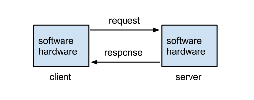
Clients send Requests – Clients are machines running software that generate network Requests that are sent to a Server.

  • For ADC, Clients are usually web browsers or any other client software that generates server Requests using the HTTP protocol.

Servers Respond to Requests – Servers receive the client’s Request, do some processing, and then send a Response back to the client.

  • For ADC, Servers are usually web servers that receive HTTP requests from clients, perform the HTTP Method (i.e. command) contained in the request, and then send back the response.

Machines are both Clients and Servers – when a machine or program sends out a Request, that machine/program is a Client. When a machine or program receives a Request from another machine, then this machine/program is a Server. Many machines, especially ADC machines, perform both client and server functions.

  • ADCs receive HTTP Requests from clients, which is a Server function. ADCs then forward the original request to a web server, which is a Client function.

What’s in a Request?

Requests are sent to Web Servers using the HTTP protocol – Web Browsers use the HTTP protocol to send Requests to Web Servers. Web Servers use the HTTP protocol to send Responses back to Web Browsers. (Image from Wikimedia)

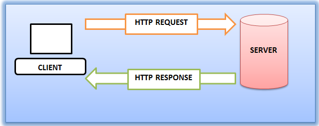
  • Protocol – A protocol defines a vocabulary for how machines communicate with each other. Since web browsers and web servers use the same protocol, they can understand each other.

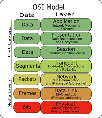
HTTP is an OSI Layer 7 protocol – HTTP is defined by the OSI Model as a Layer 7, or application layer, protocol. Layer 7 protocols run on top of (encapsulated in) other lower layer protocols, as detailed later. (image from Wikimedia)

HTTP Request Commands – HTTP Requests contain commands that the web server is intended to carry out. In the HTTP Protocol, Request Commands are also known as Request Methods.

  • HTTP GET Method – The most common Command in an HTTP Request is GET, which asks the web server to send back a file. In other words, web servers are file servers.
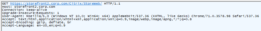
  • Shown below is an HTTP Request with the first line being the GET Method. Right after the GET command is the path to the file that the browser wants to download.
  • Other HTTP Request Methods are used by clients to upload files or data to the web server and will be detailed in Part 2.

HTTP Path – Web servers can host thousands of files but Web Servers will only download one file at a time. Inside the GET Request is the path to a specific file. In HTTP, the path format is something like /directory/directory/file.html.

  • The file path uses forward slashes, not backslashes, because HTTP was originally written for UNIX servers, which uses forward slashes in its file paths.
  • If you enter a directory path but you don’t provide a filename, then the web server will give you the configured default file for that directory instead of giving you every file in the directory.

The Path is one component of the HTTP Request URL, which looks something like https://en.wikipedia.org/wiki/Hypertext_Transfer_Protocol.

  • In a Citrix ADC policy expression, you can extract the HTTP path from the HTTP Request URL by entering HTTP.REQ.URL.PATH.
  • More info on URLs will be provided later in Part 2

Addresses Overview

Unique addresses – Every machine on a network has at least one address. Addresses are unique across the whole Internet; only one machine can own a particular address. If you have two machines with the same address, which machine receives the Request or Response?

Requests are sent to a Destination Address – when the client sends a request to a web server, it sends the request to the destination server’s address. This is similar to email when you enter the address of the recipient. The server’s address is put in the Destination Address field of the Request Packet.

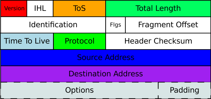
  • Shown below is an IP Packet (Layer 3 Packet) that contains a field for the Destination Address. (image from wikimedia)

The network forwards packets to the Destination Address – Request packets are placed on a Network and the Network forwards the request to the destination.

  • Multiple network hops – there are usually multiple network hops between the client and the server. Each hop reads the Destination Address in the packet to know where to send the packet next. This routing process is detailed later.

Web Servers reply to the Source Address – when the Request Packet is put on the network, the client machine inserts its own address as the Source Address. The web server receives the Request and performs its processing and uses the following process to send the Response back to the client:

  1. The Web Server extracts the client’s Source Address from the Request Packet.
  2. The Web Server creates a Response Packet and puts the original Source Address in the Destination Address of the Response Packet.
  3. The Response packet is placed on the network, which forwards the Response packet to the Response’s Destination Address, which formerly was the Source Address of the Request.

Two network paths: Request path, and Response path – If you don’t receive a Response to your Request, then either the Request didn’t make it to the Server, or the Response never made it from the Server back to the Client. The key point is that there are two communication paths: the first is from Client to Server, and the second is from Server to Client. Either one of those paths could fail. Many ADC networking problems are in the reply/response path and not necessarily in the request path.

  • Wrong Source Address – If the original Source Address in the request packet is wrong or missing, then the response will never make it back to the client. This is especially important for client devices, like ADC, that have multiple source addresses that it can choose from. If a non-reachable address is placed in the Source Address field, then the Response will never come back.

Numeric-based addresses – All network addresses are ultimately numeric, because that’s the language that machines understand. Network packets contain Source address and Destination address in numeric form. Routers and other networking equipment read the numeric addresses, perform a table lookup to find the next hop to reach the destination, and quickly place the packet on the next interface to reach the destination. This operation is much quicker if addresses are numbers instead of words.

Layer-specific addresses – Different OSI layers have different layer-specific addresses, each of which is detailed later in this article:

  • MAC Addresses are Layer 2 addresses.
  • IP Addresses are Layer 3 addresses.
  • Port numbers are Layer 4 addresses.

IP Addresses – every Client and Server on the Internet has a unique IP address. Requests are sent to a Destination IP Address. Responses are sent to the original Source IP Address. How the packets get from Source IP address to Destination IP address and back again will be detailed later.

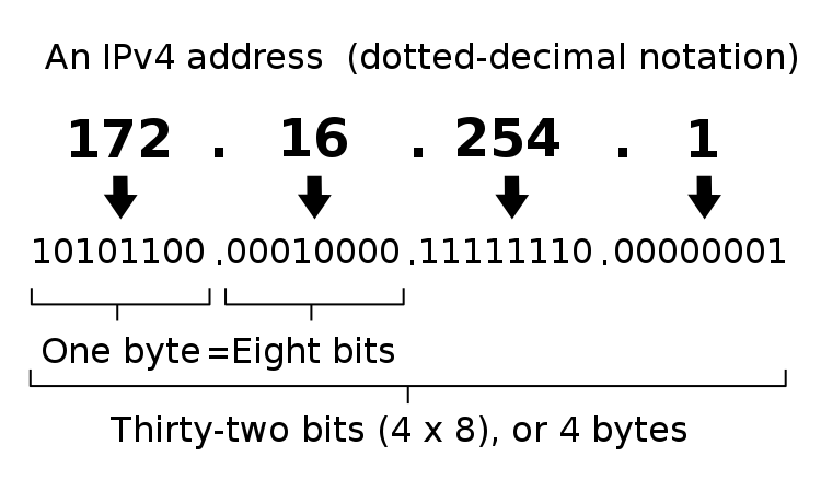
  • IP Address format – Each IP address is four numbers separated by three periods (e.g. 216.58.194.132). Each of the four numbers must be in the range between 0 and 255. Most network training guides cover IP addressing in excruciating detail so it won’t repeated here. IP addressing design is inextricably linked with overall network routing design.
  • Shown below is the format of IP v4 addresses. (image from wikimedia)

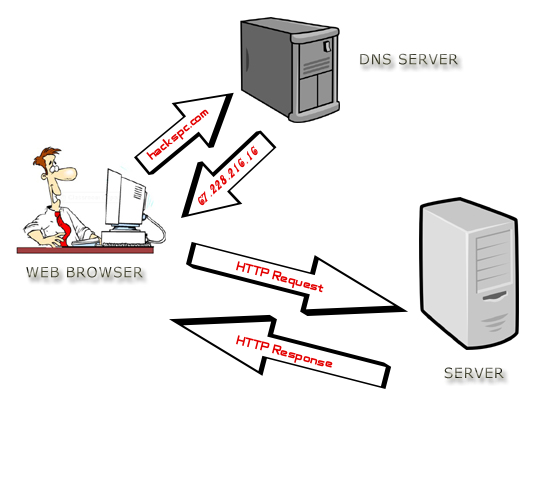
Human-readable addresses – When a human enters the destination address of a Web Server, humans much prefer to enter words instead of numbers, but machines only understand numbers, so there needs to be a method to convert the word-based addresses into numeric-based addresses. This conversion process is called DNS (Domain Name System), which will be detailed later. Essentially there’s a database that maps every word-based address into a number-based address. (image from wikimedia)

Web Servers and File Transfer

Web Servers are File Servers – essentially, Web Servers are not much more than file servers. A Web Client requests the Web Server to send it a file and the Web Server sends back a file.

Web Clients use the HTTP Protocol to request files from a Web Server. Web Servers use the HTTP Protocol to send back the requested file.

  • Web Clients can be called HTTP Clients.
  • Web Clients are sometimes called User Agents.

Web Clients are responsible for doing something meaningful with the files downloaded from Web Servers – Clients can do one of several things with the files downloaded from a Web Server:

  • Display the file’s contents to the user
    • HTML files and image files are usually rendered by a browser and displayed to the user.
    • Client-side apps or scripts can extract data from downloaded data files (e.g. JSON files) and then display the data in a user-friendly manner.
  • Launch a program to process the file
    • e.g. launch Citrix Workspace app to initiate a Citrix ICA session based on the contents of the downloaded .ica file.
  • Store the file on the file system
    • e.g. save the file to the Downloads folder.

Web Browsers – Web Browsers are a type of Web Client that usually want to display the files that are downloaded from Web Servers.

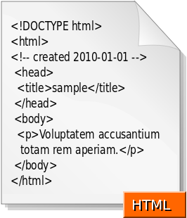
  • HTML and CSS – HTML files are simple text files that tell a browser how to structure content that is shown to the user. Raw HTML files are not designed for human consumption. Instead, HTML files should be processed by a web rendering engine (e.g. web browser), which converts the HTML file into a human viewable format. When a non-browser, client-side program downloads a HTML file, the client-side program is able to call an API (e.g. Webview API) to render the HTML file and display it to the user. Here are the contents of a sample HTML file downloaded from a web server. Notice the <> tags. (image from Wikimedia)
  • CSS – CSS (Cascading Style Sheet) files tell Browsers how to render HTML files using a particular theme (e.g. fonts, colors).
  • Images – Images are rendered by the Browser and displayed to the user. There are many different image formats and browsers need to be able to convert the image formats into graphics.
  • Scripts – .js files (JavaScript) files are downloaded by the browser and executed by the browser. JavaScripts usually modify the the HTML that is shown to the user.
  • Data files – Data files (e.g. JSON) are processed by JavaScript running inside the web browser.

HTML vs HTTP – HTTP is a network file transfer protocol (request/response). HTML files are just one of the types of files transferred by HTTP. You’ll find that most HTTP file transfers are not HTML files.

  • Any program that wants to download files from a server can use the HTTP protocol. HTTP is used by far more than just web browsers.
  • HTTP is the language of the cloud. Almost every communication between cloud components uses HTTP as the transfer protocol.

Other Web Client Types – other types of client programs use HTTP Protocol to download files from Web Servers:

  • API Web Clients – API Web Clients (programs/scripts) can use an HTTP-based API to download data files from a web server. These data files are typically processed by a client-side script or program.
  • Downloaders – some Web Clients are simply Downloaders, meaning all they do is use HTTP to download files and store them on the hard drive. Later, the user can do something with those downloaded files.

Web Server Scripting

Web Server Scripting – web servers can do more than just file serving: they can also run server-side scripts that dynamically modify the files before the files are downloaded (sent back) to the requesting web client. This allows a single web server file to provide different content to different clients. The file’s content can even be retrieved from a database.

Web Server Script Languages – different web server programs support different server-side script languages. These server-side script languages include: Java, ASP.NET, Ruby, PHP, Node.js, etc.

  • The Web Server runs a script interpreter for specific file types. (image from wikimedia)
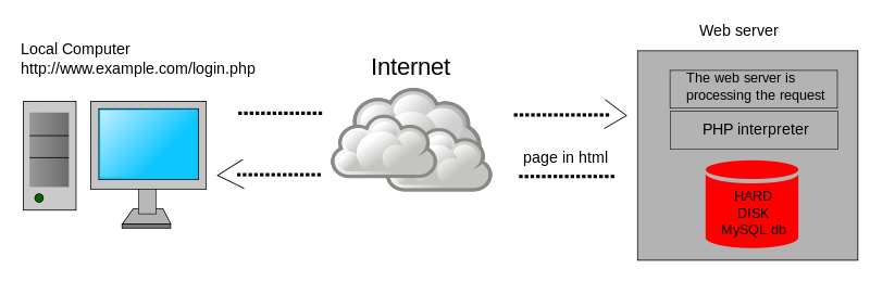
  • FIle Extensions and Server-side Script Processing – When a Web Client requests a file with a specific extension (e.g. .php), the server-side PHP script engine processes the file (runs the script). Output from the script is sent as an HTTP Response. Files without the .php extension are returned as raw files. It is not possible to download the raw .php file without the script engine first processing it.

Web Client Data Upload

Web Clients can include data and attachments in the HTTP Request –  A Web Client sometimes needs to send data to a Web Server so the Web Server can send back a client-specific response. This client-side data is included in the HTTP request and can take one of several forms:

  • URL Query String – a GET request includes a path to the file that the Web Client wants. At the end of the path, the Web Client can append arguments in the form of a URL Query String, which looks like ?arg1=value1&arg2=value2. A script on the Web Server reads this query string and adjusts the response accordingly. (image from wikipedia)
  • Cookies – Web Servers frequently attach small pieces of data called Cookies to HTTP Responses. Web Clients are expected to attach these Cookies to every HTTP Request sent to the same Web Server. Cookies are used to manage Web Sessions and Web Authentication, as described later.
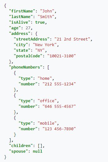
  • JSON or XML document – client-side scripts or programs generate JSON or XML documents and send them to a Web Server. The JSON and XML documents typically contain arguments or other data that a Web Server reads to dynamically generate a response that should be sent back to the client. The response can also be a JSON or XML document and doesn’t have to be an HTML document. For JSON/XML responses, the client-side program reads the response and does something programmatically with it. For example, a JavaScript Web Client can read the contents of a JSON file response and show it to the user as an HTML Table. Here’s a sample JSON from Wikipedia.
  • HTML Form Data – Many HTML pages contain a form. Users enter data into the form’s fields. The data that the user entered is attached to an HTTP Request and sent to the web server for processing. A very common HTML form is authentication (username and password). HTML Form Data can also be uploaded by JavaScript as JSON/XML instead of as raw HTML Form Data.
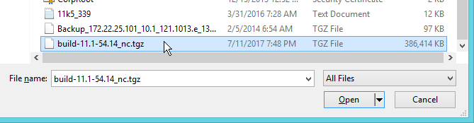
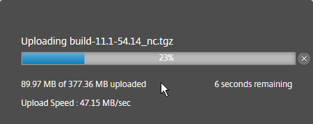
  • Raw File – Sometimes a Web Client needs to upload a raw file and store it on the Web Server. The raw file is included in the HTTP Request. Users are typically prompted to select a file that the user wants to upload to the Web Server.

Web Client Scripting

Web Browser Scripting – Client-side scripts (JavaScript) add animations and other dynamic features to HTML web pages.

  • Reload Web Page vs Dynamic HTML – in simple HTML pages, when the user clicks a link, the entire web page is downloaded from the Web Server and reloaded in the user’s browser. In more modern HTML pages (aka Single Page Applications), when a user clicks a link or submits a form, JavaScript intercepts the request and sends the request or form data as JSON to the Web Server. The Web Server replies with a JSON document, which JavaScript uses to dynamically change the HTML shown in the user’s browser. This is usually much quicker and more dynamic than fully reloading a browser’s webpage.
  • Web Browser Plug-ins – Additional client-side scripting languages can be added to web browsers by installing plug-ins, like Flash and Java. But today these plug-ins are becoming more rare because JavaScript can do almost everything that Flash and Java can do.

HTTP is the Core of Modern IT

Everybody working in IT today must know HTTP. Here are some IT roles where HTTP knowledge is essential:

  • Server Administrators that build Web Servers or any other server-side software that use HTTP to communicate with clients.
  • Database Administrators where their primary client is HTTP Web Servers that deliver HTML web pages.
  • Desktop Administrators that manage and support HTTP-based client-side programs, including Web Browsers. Almost every modern client-side application uses HTTP, even if that program is not a Web Browser.
  • Network Administrators that forward HTTP Requests to Web Servers and then forward the HTTP Responses back to the Web Clients.
  • Security Teams that inspect the HTTP Requests and HTTP Responses for malicious content.
  • Developers that write code that uses HTTP as the application’s network communication protocol. This is especially true for modern API-based micro-services.
  • Scripters and DevOps teams that write scripts to control other machines and applications. The scripting languages ultimately use HTTP Protocol to send commands. REST API is based on the HTTP protocol.
  • Cloud Administrators since Cloud = HTTP. When an application is “written for the cloud”, that means the app is based on the HTTP protocol.
    • Cloud Storage is accessed using HTTP protocol instead of other storage protocols like SMB, NFS, iSCSI, and Fibre Channel.
  • Mobile Device Administrators since mobile apps are nothing more than Web Clients that use HTTP protocol to communicate with web-server hosted applications.

Web Server Services and Web Server Port Numbers

Web Server Software – there are many web server programs like Microsoft IIS, Apache, NGINX, Ember (Node.js), WebLogic, etc. Some are built into the operating system (e.g. IIS is built into Windows Server), and others must be downloaded and installed.

Web Server Software runs as a Service – The Web Server Software installation process creates a Service (or UNIX/Linux Daemon) that launches automatically every time the Web Server reboots. Services can be stopped and restarted. Server admins should already be familiar with Server Services.

Servers can run multiple Services at the same time – A single Server can run many Services at the same time: an Email Server Service, an FTP Server Service, an SSH Server Service, a Web Server Service, etc. There needs to be some way for the Client to tell the Server that the Request is to be sent to the Web Server Service and not to the SSH Service.

Services listen on a Port Number – when the Web Server Service starts, it begins listening for requests on a particular Port Number (typically port 80 for unencrypted HTTP traffic, and port 443 for encrypted SSL/TLS traffic). Other Server Services listen on different port numbers. It’s not possible for two Services to listen on the same port number on the same IP address.

Clients send packets to a Destination Port Number – When a Client sends an HTTP Request to a Web Server Service, the Client adds a Destination Port Number to the packet. If you open a browser and type a HTTP URL into the browser’s address bar, by default, the browser will send the packet to Port 80, which is usually the port number that Web Server Services are listening on.

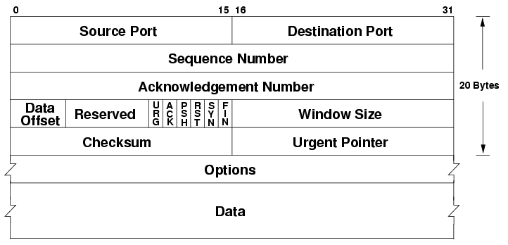
  • Shown below is a TCP Packet Header with a field for Destination Port. (image from wikimedia)

Client Programs and Client Ports

Multiple Client Programs – multiple client programs can be running concurrently on a single Client machine; for example: Outlook, Internet Explorer, Chrome, Slack, etc. When the Response is sent from the Server back to the Client, which client-side program should receive the Response?

Client Ephemeral Ports – whenever a client program sends a request to a Server, the operating system assigns a random port number between 1024 and 65535 to the client process. This range of ephemeral client port numbers varies for different client operating systems.

  • Windows ephemeral (dynamic) ports are usually between 49152 and 65535. For details, see Microsoft 929851.

Servers send the Response to the Client’s Ephemeral Port – The Client’s Ephemeral Port is included in the Source Port field of the Request packet. The Server extracts the Source Port from the Request Packet and puts the original source port in the Response packet’s Destination Port field.

  • If you view Requests and Responses in a network trace, you’ll see that the port numbers are swapped for responses vs requests.

Each Client Request can use a different Ephemeral Port – A client program can send multiple requests to multiple server machines, and each of these outstanding requests can have a unique Client Ephemeral port.

Summary of the Network Packet Fields discussed so far – In order for Packets to reach the Server Service and return to the Client Program, every network packet must contain the following fields:

  • Destination IP Address – the Server’s IP address
  • Destination Port – port 80 or port 443 for Web Server Services
  • Source IP Address – the Client’s IP address
  • Source Port – the ephemeral port assigned by the operating system to the client program

Sessions

Sessions Overview

Single Request vs Session – One HTTP Request is accompanied by one HTTP Response. But you usually need to combine multiple HTTP Requests and Responses into something called a Session. For example, if you authenticated to a web server, you shouldn’t have to authenticate every HTTP Request that you send to the Web Server. After authentication is complete, an HTTP Session is established which allows multiple HTTP Requests and Responses to use the same authentication context.

Session Context – Context is the data that defines a session. The first HTTP Response includes a session identifier, which is usually in a cookie. This session identifier (e.g. cookie) is included with the next HTTP Request so the Web Server knows which session is being used. The Web Server looks up the existing context information so it doesn’t have to start over (e.g. re-authenticate the user).

Sessions and the OSI network model – each layer of the OSI network model has its own conception of sessions, but the idea is the same: a session = multiple requests/responses in the same context.

Here are the Session constructs for each layer of the OSI network model:

  • Layer 4 – TCP Connection
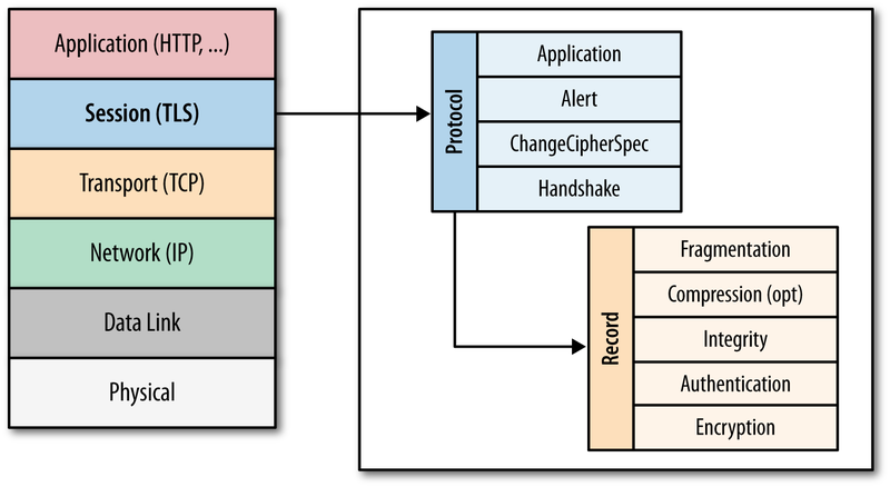
  • Layer 6 – SSL/TLS Session
  • Layer 7 – HTTP Session
  • Web Server Session – doesn’t map to the OSI Model. Think “shopping carts”

The OSI model is detailed in every introductory network training book/video/class. In essence, application traffic starts at Layer 7 (HTTP Protocol), which is embedded down the stack inside the Layer 6 packet (typically SSL/TLS encrypted session), then embedded down the stack again into a Layer 4 TCP packet. When the packet is received at the destination, Layer 4 is removed revealing Layer 6. Then Layer 6 is removed revealing Layer 7, which is finally given to the application or service.

Higher layer sessions require lower layer sessions – Sessions at higher layers require Sessions (or Connections) at lower layers to be established first. For example, HTTP Requests can’t be sent unless a TCP Connection is established first.

Session management offloading – Some of the session handling tasks performed by servers can be offloaded to an ADC appliance. For example, Citrix ADC can handle all of the client-side TCP Connections and client-side TLS/SSL encryption sessions so the Web Servers can focus on serving content instead of managing sessions.

Network Sessions

Transport ProtocolTCP (Layer 4) is a Transport Protocol. TCP does a number of things, including the following:

  • Reorder packets that arrive out of order.
    • When a Request or Response is broken into multiple packets, the destination needs to reassemble the packets in the correct order. Each packet contains a Sequence Number. The first packet might have Sequence Number 1, while the second packet might have Sequence Number 2, etc. These Sequence Numbers are used to reassemble the packet in the correct order.
  • The destination acknowledges every packet that it receives so the source knows that the packet arrived at the destination. If the source does not receive an acknowledgement, then the source will retransmit.
    • Acknowledging every packet introduces delay (latency) so TCP uses a dynamically-sized Window to allow the source to send multiple packets before it receives an acknowledgement.
  • Error checking
    • Every TCP packet includes a checksum that was computed at the source. If the computed checksum on the received packet does not match the checksum inside the packet, then the packet is dropped and no acknowledgement is sent to the sender. Eventually the sender will retransmit the missing/corrupted packet.
  • If congestion, the source needs to back off.
    • TCP has several algorithms for handling congestion. These algorithms control how the Windows size grows and shrinks, and also controls how often acknowledgements are sent.

TCP and UDP Overview – there are two Layer 4 Session protocols – TCP, and UDP. TCP handles many of the Transport services mentioned above. UDP does not do any of these services, and instead requires higher layer protocols to handle them.

  • Citrix EDT (Enlightened Data Transport) is an example higher layer protocol that runs on top of UDP because EDT doesn’t want TCP to interfere with the EDT’s Transport services (reassembly, retransmission, etc.). In other words, Citrix EDT replaces the transport capabilities of TCP.
  • HTTP/3 (version 3) also replaces TCP with its own transport layer and thus HTTP/3 runs on top of UDP instead of TCP.
  • The problem with TCP is that it is a generic transport protocol that isn’t specifically designed for specific higher-level protocols like HTTP and Citrix ICA.

TCP Port Numbers and UDP Port Numbers are different – Each Layer 4 protocol has its own set of port numbers. TCP port numbers are different from UDP port numbers. A Server Service listening on TCP 80 does not mean it is listening on UDP 80. When talking about port numbers, you must indicate if the port number is TCP or UDP, especially when asking firewall teams to open ports. Most of the common ports are TCP, but some (e.g. Voice) are UDP.

  • Increasingly, you will need to open both UDP and TCP versions of each port number. For example, Citrix HDX/ICA traffic can run on both TCP 1494 and UDP 1494 (EDT protocol). ICA traffic proxied through Citrix Gateway can use both TCP 443 and UDP 443.

TCP Protocol (Layer 4)

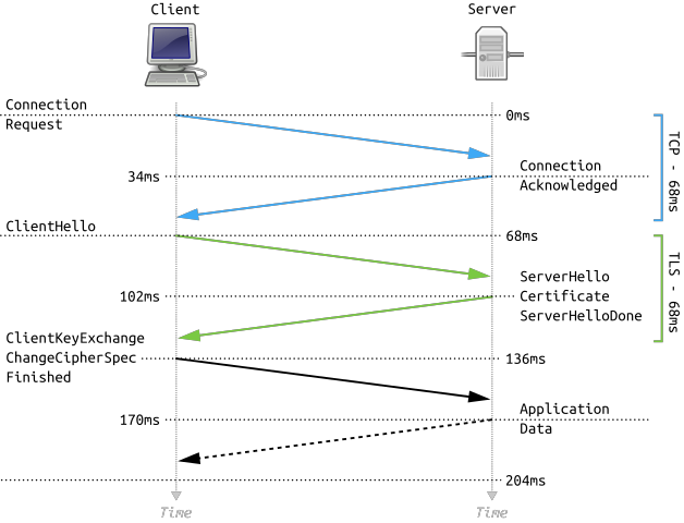
HTTP requires a TCP Connection to be established first – When an HTTP Client wants to send an HTTP Request to a web server, a TCP Connection must be established first. The Client and the Server do the three-way TCP handshake on TCP Port 80. Then the HTTP Request and HTTP Response is sent over this TCP connection. HTTP is a Layer 7 protocol, while TCP is a Layer 4 protocol. Higher layer protocols run on top of lower layer protocols. It is impossible to send a Layer 7 Request (HTTP Request) without first establishing a Layer 4 session/connection.

TCP Three-way handshake – Before two machines can communicate using TCP, a three-way handshake must be performed:

  1. The TCP Client initiates the TCP connection by sending a TCP SYN packet (connection request) to the Server Service Port Number.
  2. The Server creates a TCP Session in its memory, and sends a SYN+ACK packet (acknowledgement) back to the TCP client.
  3. The TCP Client receives the SYN+ACK packet and then sends an ACK back to the TCP Server, which finishes the establishment of the TCP connection. HTTP Requests and Responses can now be sent across this established TCP connection.

TCP Connections are established between Port Numbers – The TCP Connection is established between the Client’s TCP Port (ephemeral port), and the Server’s TCP Port (e.g. port 80 for web servers). Different port numbers on either side means different TCP Connections.

  • TCP Connections run on top of Layer 3 IP traffic. Layer 3 traffic uses an IP Address for the source and an IP address for the destination. If either of these addresses are different, then that’s a different TCP Connection.
  • In summary, each combination of Source IP, Destination IP, Source Port, and Destination Port is a different TCP Connection.

Multiple Clients to one Server Port – A single Server TCP Port can have many TCP Connections with many clients. Each combination of Client Port/Client IP with the Server Port is considered a separate TCP Connection. You can view these TCP Connections by running netstat on the server.

  • Netstat shows Layer 4 onlynetstat command shows the TCP connection table (Layer 4) only. Netstat does not show HTTP Requests (Layer 7).
  • Netstat show TCP connections but not UDP – There’s no such thing as a UDP Connection, so Netstat will not show them. However, Netstat can show you any services that are listening on UDP port numbers.

TCP Connection Termination – clients that are done communicating with a server can send a TCP Finish packet that tells the server to delete the TCP connection information from the server’s memory (TCP connection table).

  • TCP Connection time limit – If the client never sends a Finish packet, then servers have a default time limit for inactive TCP connections. Once that time limit expires. the server will send a Finish packet to the client and then remove the TCP connection from its memory. If the client later wants to send an HTTP Request, then the client must first perform the three-way TCP handshake again.

TCP and Firewalls – Firewalls watch for TCP handshake packets. For every SYN packet allowed through the firewall, the firewall opens a port in the opposite direction so the SYN+ACK packet can be sent back to the client. This means firewall administrators do not have to explicitly permit reply traffic since the firewall will do it automatically.

Use Telnet to verify that a Service is listening on a TCP Port number – when you telnet to a server machine on a particular port number, you are essentially completing the three-way TCP handshake with a particular Server Service. This is an easy method to determine if a Server machine has a Service listening on a particular port number and that you’re able to communicate with that port number.

  • Telnet doesn’t work with UDP services because there’s no three-way handshake for UDP.

TCP Three-way handshake can be expensive – TCP handshakes and TCP session management require CPU, memory, and bandwidth on the web servers. For web servers that serve content to thousands of clients, TCP session management can consume a significant portion of the web server’s hardware resources.

  • Citrix ADC can offload TCP session management – Citrix ADC handles all of the TCP sessions between the thousands of clients and the one Load Balancing VIP. Citrix ADC then opens a single TCP session between the ADC and the Web Server. All HTTP requests received by the ADC’s clients are sent across the single web server TCP session, even if the HTTP Requests came from multiple client TCP connections. This means that an ADC might have thousands of client-side TCP connections but only one server-side TCP connection, thus offloading TCP duties from the web server.
  • HTTP/2 Multiplexing – In HTTP 1.1, when an HTTP Request is sent across a TCP session, no other HTTP Request can be sent until the web server sends back a response for the original HTTP Request. In HTTP/2, multiple HTTP Requests can be multiplexed onto the same TCP connection and the web server will reply to all of them when it can.
    • In HTTP 1.1, ADC will open as many TCP connections to the web server as needed to support multiple concurrent HTTP requests. HTTP/2 should only need a single TCP connection for all HTTP requests.

UDP Protocol (Layer 4)

UDP is Sessionless – UDP is a much simpler protocol than TCP. For example, there’s no three-way handshake like TCP. Since there’s no handshake, there’s no UDP session.

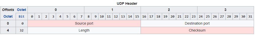
  • Notice in the UDP header that there are no Sequence number fields, no Acknowledgement number fields, and no Window size field like there is in TCP. (image from wikipedia)

No Sequence Numbers – UDP packets do not contain sequence numbers. If packets arrive out of order, UDP cannot determine this, and cannot reassemble them in the correct order.

No acknowledgements – When UDP packets are received, the receiver does not send an acknowledgement back to the sender. Since there are no acknowledgements, if a UDP packet is lost, there’s no way for the UDP sender to detect this and thus no way for UDP to resend the packet like TCP does.

  • Audio uses UDP – For audio traffic, there’s usually no point in resending lost packets. Getting rid of retransmissions makes UDP more efficient (less bandwidth, less latency) than TCP for audio.

Why UDP over TCP? – TCP session information is contained in every TCP packet, thus making every TCP packet (20 byte header) bigger than a UDP packet (8 byte header). The smaller header size and the lack of three-way handshake means UDP is a lightweight protocol that performs better on high latency and low bandwidth links.

  • However, some of the transport services provided by TCP are needed by Layer 7 protocols. New transport protocols are being developed to replace TCP. These new transport protocols need to do their work without TCP interfering with them so the new transport protocols run on top of UDP instead of TCP.
  • Citrix EDT (Enlightened Data Transport) is an example UDP-based transport protocol. HTTP/3 has its own transport protocol that will also run on top of UDP instead of TCP.

HTTP Basics

HTTP Protocol Overview

URLs – when a user wants to visit a website, the user enters a URL into a web browser’s address bar. An example URL is https://en.wikipedia.org/wiki/URL. Each URL can be broken up into three sections:

  • URL Scheme = https:// or http:// – the first part of the URL, also known as the scheme, specifies the Layer 7 and Layer 6 protocols that the browser will use to connect to the web server.
    • HTTP Protocol can be transmitted unencrypted, which is the http:// scheme. The http:// scheme defaults to TCP Port 80.
    • Encrypted HTTP traffic means regular unencrypted Layer 7 HTTP packets embedded in a Layer 6 SSL/TLS session. HTTP Encryption is detailed in Part 2. Users enter https:// scheme to indicate that the user wants the HTTP traffic to be encrypted, assuming the Web Server is configured to accept encrypted traffic. The https:// scheme defaults to TCP Port 443.
  • URL Hostname = en.wikipedia.org – the second part of the URL is the human-readable DNS host name that translates to the web server’s IP address. The hostname comes after the scheme but before the URL Path.
    • The Web Browser uses DNS to convert the URL host name into an IP Address for the web server.
    • The Web Browser creates a TCP connection to the web server’s IP Address on port 80 or port 443.
  • URL Path = /wiki/URL – the remaining part of the URL is the Path and Query. The Path indicates the path to the file that you want to download.
    • The Web Browser sends an HTTP GET Request for the specified path to the web server across the already established TCP connection.

Browser handling of URLs – The Browser performs different actions for each portion of the URL:

  • Browser uses the URL Scheme to define how the browser connects to the URL Host name.
  • Browser uses the URL Host name as the destination for the TCP Connection and the HTTP Requests.
    • The Web Browser includes the entered URL Host name in the Host header of each HTTP Request Packet sent to the web server so that the web server knows which web site the user is trying to access. The HTTP Request Host header is detailed in Part 2.
  • Browser includes the URL Path in the GET method of the initial HTTP Request Packet.
    • For the example URL shown above, the first line of the HTTP Request packet is this: GET /wiki/URL

Why forward slashes in URLs? – Web Server programs were originally developed for UNIX and Linux, and thus URLs share some of the characteristics of Linux/UNIX.

  • Some URLs are case sensitive – Since UNIX/Linux is case sensitive, file paths in URLs are sometimes case sensitive. This is more likely to be true for Web Server software running on UNIX/Linux machines than Windows machines.

HTTP Packet

HTTP Request Method – at the top of every HTTP Request packet is the HTTP Method or Request Command. This Method might be something like this: GET /Citrix/StoreWeb/login.aspx HTTP/1.1

  • GET is a simple request to fetch a file.
  • If no URL path is specified, then the first line of the HTTP Request is simply GET / HTTP/1.1 where the / means that it’s requesting the default file in the root folder of the website. Web Servers are configured to return a default file if no specific file is requested.
  • There are other HTTP request methods, like POST, PUT, DELETE, etc. These other HTTP Request Methods are used in REST APIs, JavaScript, and HTML Form Uploads and are partially detailed in Part 2.

HTTP Response Code – at the top of every HTTP Response is a code like this: HTTP/1.1 200 OK. Different codes mean success or error. Code 200 means success. You’ll need to memorize many of these codes.

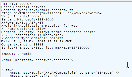
Header and Body – HTTP Packets are split into two sections: header, and body.

  • HTTP Headers – Below the Request Method or below the HTTP Response Code, are a series of Headers. Web Browsers insert Headers into requests. Web Servers insert Headers into responses. Request Headers and Response Headers are totally different. You’ll need to memorize most of these Headers.
  • HTTP Body – Below the Headers is the Body. Not every HTTP Packet has a Body.
    • In a HTTP Response, the HTTP Body contains the actual downloaded file (e.g. HTML file).
    • HTTP GET Requests do not have a Body.
    • HTTP POST Requests have a Body. The HTTP Body can contain data (HTML Form Data, JSON, XML, raw file, etc.) that is uploaded with the Request.

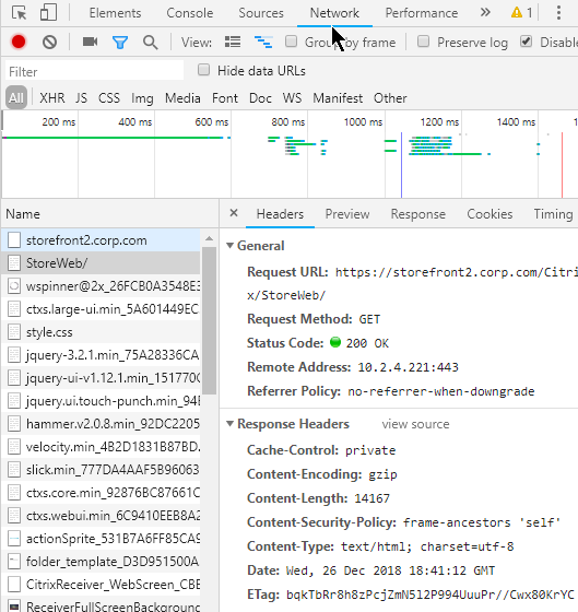
Raw HTTP packets – To view a raw HTTP packet, use your browser’s developer tools (F12 key), or use a proxy program like Fiddler. In a Browser’s Developer Tools, switch to the Network tab to see the HTTP Requests and HTTP Responses.

Multiple HTTP requests – A single webpage requires multiple HTTP requests. When an HTML file is rendered by a Web Browser, the HTML file contains links to supporting files (CSS files, script files, image files) that must be downloaded from the web server. Each of these file downloads is a separate HTTP Request.

  • HTTP and TCP Connections – Every HTTP Request requires a TCP Connection to be established first. Older Web Servers tear down the TCP Connection after every single HTTP Request. This means that if a web page needs 20 downloads, then 20 TCP Connections, including 20 three-way handshakes, are required. Newer Web Servers keep the TCP Connection established for a period of time, allowing each of the 20 HTTP Requests to be sent across the existing TCP Connection.

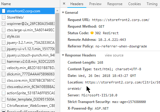
HTTP Redirects – one HTTP Response Code that you must understand is the HTTP Redirect.

  • Redirect Behavior – When a HTTP Client sends an HTTP Request to a Web Server, that Web Server might send back a 301/302 Redirect and include a new location (new URL). The HTTP Client is then expected to send a HTTP Request to the new Location (URL) instead of the old URL.
  • Redirect HTTP Response – HTTP Response packets for a Redirect have response code 301 or 302 instead of response code 200.
    • The HTTP Response Header named Location identifies the new URL that the browser is expected to navigate to.
  • Redirect usage – Redirects are used extensively by web applications. Most web-based applications would not function without redirects. A common usage of Redirects is in authenticated websites where an unauthenticated user is redirected to a login page, and after login, the user is redirected back to the original web page. Or a redirect can redirect you to a default page (e.g. redirect to “/Director”)
  • Not all HTTP Clients support HTTP Redirects – Web Browsers certainly can perform a redirect. However, other HTTP Clients (e.g. Citrix Receiver) do not follow Redirects.

Additional HTTP concepts will be detailed in Part 2.

Networking

Layer 2 (Ethernet) and Layer 3 (Routing) Networking

Subnet – all machines connected to a single “wire” are on the same subnet. Machines on the subnet can communicate directly with other machines on the same subnet. When one machine puts electrical signals on the wire, every other machine on the same wire sees the electrical signals. A network packet (or frame) is a collection of electrical signals.

Routers – If two machines are on different subnets, then those two machines can only communicate with each other through an intermediary device that is connected to both subnets. This intermediary device is called a router. The router is connected to both subnets (wires) and can take packets from one subnet and put them on the other subnet.

Layer 2 – When machines on the same subnet want to communicate with each other, they use a Layer 2 protocol, like Ethernet.

Layer 3 – When machines on different subnets want to communicate with each other, they use a Layer 3 protocol, like IP (Internet Protocol).

Local IP address vs remote IP address

Destination is either local or remote – since different protocols are used for intra-subnet (Layer 2) and inter-subnet (Layer 3), the machines need to know which machines on are on the local subnet, and which machines are on a remote subnet.

IP Address Subnet Mask – all machines have an IP address. All machines are also configured with a subnet mask. The subnet mask defines which bits of the machine’s IP address are the subnet ID and which bits of the IP address are the machine’s host ID. If two machines have the same subnet ID, then those two machines are on the same subnet. If two machines have different subnet IDs, then those two machines are on different subnets.

  • IPv4 addresses are 32-bits in length. The left part of the address is the subnet ID. The right part of the address is the machine’s host ID. The subnet mask designates where the left part (subnet ID) ends and the right part (host ID) begins. If the subnet mask is 24 bits, then the first 24 bits of the IP address are the subnet ID, and the last 8 bits are the machine’s host ID.
    • The subnet mask is usually between 8 bits and 30 bits. The variability of subnet mask length allows a router to aggregate many smaller subnet IDs into one larger subnet ID and thus improve router efficiency.
    • IPv6 changes how subnet ID and host ID are determined. IPv6 addresses are 128-bits in length. The subnet ID is the first 64 bits, and the host ID is the last 64 bits, which means the subnet mask is 64 bits. Routers still have the flexibility of reducing the subnet mask to less than 64 bits so multiple small subnets can be aggregated into one larger subnet. However, the host ID is always 64 bits.
  • For example, if a machine with address 10.1.0.1 wants to talk to a machine with address 10.1.0.2, and if the subnet mask is 255.255.0.0, when both addresses are compared to the subnet mask, the masked results are the same, and thus both machines are on the same subnet, and Ethernet is used for the communication.
  • If the masked results are different, then the other machine is on a different subnet, and IP Routing is used for the communication.
  • There is a considerable amount of readily available training material on IP Addressing and subnet masks so I won’t repeat that material here.

Wrong Subnet Mask – If either machine is configured with the wrong subnet mask, then one of the machines might think the other machine is on a different subnet, when actually it’s on the same subnet. Or one of the machines might think the other machine is on the same subnet, when actually it’s on a different subnet. Remember, communication in the same same subnet uses a different communication protocol than between subnets and thus it’s important that the subnet mask is configured correctly.

Layer 2 Ethernet communication

Every machine sees every packet – A characteristic of Layer 2 (Ethernet) is that every machine sees electrical signals from every other machine on the same subnet.

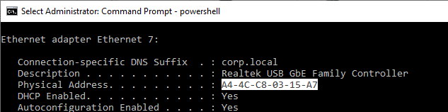
MAC addresses – When two machines on the same subnet talk to each other, they use a Layer 2 address. In Ethernet, this is called the MAC address. Every Ethernet NIC (network interface card) in every machine has a unique MAC address. Ipconfig shows it as the NIC’s Physical Address.

NICs Listen for their MAC address – The Ethernet packet (electrical signals) put on the wire contains the MAC address of the destination machine. All machines on the same subnet see the packet. If the listening NIC has a MAC address that matches the packet, then the listening NIC processes the rest of the packet. If the listening NIC doesn’t have a matching MAC address, then the packet is ignored.

  • You can override this ignoring of packets not destined to the NIC’s MAC address by turning on the NIC’s promiscuous mode, which is used by packet capture programs (e.g. Wireshark) to see every packet on the wire.

Source MAC address – When an Ethernet packet reaches a destination machine, the destination machine needs to know where to send back the reply. Thus both the destination MAC address, and the source MAC address, are included in the Ethernet packet.

  • Shown below is an Ethernet Frame with Destination MAC Address and Source MAC Address. (image from wikimedia)

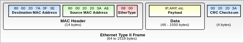
Ethernet Packet Fields – In summary, a typical Ethernet packet/frame with embedded IP packet and embedded Layer 4 packet contains the following fields:

  • Destination MAC address
  • Source MAC address
  • Destination IP address
  • Source IP address
  • Destination TCP/UDP port number
  • Source TCP/UDP port number

Other Layer 2 technologies – another common Layer 2 technology seen in datacenters is Fibre Channel for storage area networking (SAN). Fibre Channel has its own Layer 2 addresses called the World Wide Names (WWN). Fibre Channel does not use IP in Layer 3, and instead has its own Layer 3 protocol, and its own Layer 3 addresses (FCID).

ARP (Address Resolution Protocol)

Users enter IP Addresses, not MAC Addresses – when a user wants to communicate to another machine, the user enters a DNS name, which is translated to an Layer 3 IP address. If the destination IP address is on the same subnet as the source machine, then the destination IP address must first be converted to a Layer 2 MAC address. Remember, same-subnet (same wire) Layer 2 communication uses MAC addresses, not IP addresses.

  • Machines use the IP address Subnet Mask to determine if the destination IP address is local (same subnet) or remote.

Machines use Address Resolution Protocol (ARP) to find the MAC address that’s associated with a destination IP address that’s on the same subnet as the source machine.

ARP Process – The source machine sends out an Ethernet broadcast with the ARP message “who has IP address 10.1.0.2”. Every machine on the same subnet sees the message. If one of the machines is configured with IP address 10.1.0.2, then that machine replies to the source machine and includes its MAC address in the response. The source machine can now send a packet directly to the destination machine’s Ethernet MAC address.

ARP Cache – after the ARP protocol resolves an IP address to a MAC address, the MAC address is cached on the source machine for a period of time (e.g. 30 seconds). If another IP packet needs to be sent to the same destination IP address, then there’s no need to perform ARP again, since the source machine already knows the destination machine’s MAC address. When the ARP cache entry expires, then ARP needs to be performed again.

IP Conflict – a particular IP address can only be assigned to one machine. If two machines have the same IP address, then both machines will respond to the ARP request. Sometimes the ARP response will be one machine’s MAC address, and sometimes it will be the other machine’s MAC address. This behavior is typically logged as a “MAC move” or an “IP conflict“. Since only half the packets are reaching each machine, both machines will stop working.

Layer 3 on top of Layer 2

Routing to other subnets – When a machine wants to talk to a machine on a different subnet, the source machine needs to send the packet to a router. The router will then forward the packet to the destination machine on the other subnet.

Default gateway – Every client machine is configured with a default gateway, which is the IP address of a router on the same subnet as the client machine. The client machine assumes that the default gateway (router) can reach every other subnet.

  • On a ADC or UNIX/Linux device, the default route (default gateway) is shown as route 0.0.0.0/0.0.0.0.

Router’s MAC address – Since the router and the source machine are physically connected to the same Ethernet subnet, they use Ethernet MAC addresses to communicate with each other. The source machine first ARP’s the router’s IP address to find the router’s MAC address. The source machine creates a packet with the remote destination IP address and the router’s local MAC address, and then puts the packet on the wire.

  • The Destination IP Address in the packet is the final destination’s (the web server’s) IP address, and not the Router’s IP address. However, the destination MAC Address is the Router’s MAC address, and not the final destination’s MAC Address.
  • ARP across subnet boundaries – It’s not possible for a source machine to find the MAC address of a machine on a remote subnet. If you ping an IP address on a remote subnet, and if you look in the ARP cache, you might see the router’s MAC address instead of the destination machine’s MAC address. Routers do not forward Ethernet broadcasts to other subnets.
  • Router must be on same subnet as client machine – since client machines use Ethernet, ARP, and MAC addresses to talk to routers, the router (default gateway) and the client machine must be on the same subnet. More specifically, the router must have an IP address on the same IP subnet as the client machine. When the client machine’s IP address and the router’s IP address are compared to the subnet mask, the subnet ID results must match. You cannot configure a default gateway that is on a different subnet than the client machine.
  • There can only be one default route on a machine, which impacts multi-NIC machines – Some machines (e.g. ADC appliances) might be configured with multiple IP addresses on multiple subnets and multiple physical connections. Only one router can be specified as the default gateway (default route). This default gateway must be on one of the subnets that the client machine is connected to. Keep reading for details on how to handle the limitation of only a single default route.

Routing table lookup – When the router receives the packet on the MAC address of one of its NICs, and if the destination IP address in the packet is not one of the router’s IP addresses, then the router looks in its memory (routing table) to determine what network interface it needs to put the packet on. The router has a list of which IP subnet is on which router interface.

Router ARP’s the destination machine on other subnet – If the destination IP address is on one of the subnets/interfaces that the router is directly connected to, then the router will perform an ARP on that subnet/interface to get the destination machine’s MAC address. If the router is not directly connected to the subnet that contains the destination IP address, then the router will probably send the packet to another router for additional routing.

The Router makes a couple changes to the packet before it puts the modified packet on the destination interface. Here are the modifications:

  • The destination MAC address is changed to the destination machine’s MAC address instead of the router’s MAC address.
  • The source MAC address in the packet is now the router’s MAC address, thus making it easier for the destination machine to send back a reply.
  • The IP Addresses in the packet do not change. Only the MAC addresses change.

Multiple Routers and Routing Protocols

Router-to-router communication– When a router receives a packet that is destined to a remote IP subnet, the router might not be Layer 2 (Ethernet) connected to the destination IP subnet. In that case, the router needs to send the packet to another router. It does this by changing the destination MAC address of the packet to a different router’s MAC address. Both routers need to be connected to the same Ethernet subnet.

Routing Protocols – Routers communicate with each other to build a topology of the shortest path or quickest path to reach a destination IP subnet. Most of the CCNA/CCNP/CCIE training materials detail how routers perform this topology building and path selection and thus will not be detailed here.

  • ADC appliances can participate in routing protocols like OSPF and BGP. ADC can inject routes for IP destinations that only the ADC appliance might know about.

Ethernet Switches

Ethernet Subnet = Single wire – All machines on the same Ethernet subnet share a single “wire”. Or at least that’s how it used to work.

Switch backplane – Today, each machine connects a cable to a port on a switch. The switch merges the switch ports into a shared backplane. The machines communicate with each other across the backplane instead of a single “wire”.

MAC address learning – The switch learns which MAC addresses are on which switch ports.

Switches switch known MAC addresses to only known switch ports – If the switch knows which switch port connects to the destination MAC address of an Ethernet packet, then the switch only puts the Ethernet packet on the one switch port. This means that Ethernet packets are no longer seen by every machine on the wire. This improves security because NIC promiscuous mode no longer sees every packet on the Ethernet subnet.

  • SPAN port – For troubleshooting or security monitoring, sometimes you need to see every packet. Switches have a feature called SPAN or Port Mirroring that can mirror every packet from one or more source interfaces to a single destination interface where a packet capture tool is running.

Switches flood unknown MAC addresses to all switch ports – If the switch doesn’t know which switch port connects to a destination MAC address, then the switch floods the packet to every switch port on the subnet. If one of the switch ports replies, then the switch learns the MAC address on that switch port.

Switches flood broadcast packets – The switch also floods Ethernet broadcast packets to every switch port in the Ethernet subnet.

Switches and VLANs

VLANs – A single Ethernet Switch can have different switch ports in different Ethernet Subnets. Each Ethernet Subnet is called a VLAN (Virtual Local Area Network). All switch ports in the same Ethernet Subnet are in the same VLAN.

VLAN ID – Each VLAN has an ID, which is a number between 1 and 4095. Thus a Switch can have Switch Ports in up to 4095 different Ethernet Subnets.

Switch Port VLAN configuration – a Switch administrator assigns each switch port to a VLAN ID. By default, Switch Ports are in VLAN 1 and shutdown. The Switch administrator must specify the port’s VLAN ID and enable (unshut) the Switch Port.

Pure Layer 2 Switches don’t route – When a Switch receives a packet for a port in VLAN 10, it only switches the packet to other Switch Ports that are also in VLAN 10. Pure Layer 2 Switches do not route (forward) packets between VLANs.

Some Switches can route – Some Switches have routing functionality (Layer 3). The Layer 3 Switch has IP addresses on multiple Ethernet subnets (one IP address for each subnet). The client machine has the Default Gateway set to the Switch’s IP address that’s in the same subnet as the client. When Ethernet packets are sent to the Switch’s MAC address, the Layer 3 Switch forwards (routes) the packets to a different IP subnet.

DHCP (Dynamic Host Configuration Protocol)

Static IP Addresses or DHCP (Dynamic) IP Addresses – Before a machine can communicate on an IP network, the machine needs an IP address. The IP address can be assigned statically by the administrator, or the machine can get an IP address from a DHCP Server.

DHCP Process – When a DHCP-enabled machine boots, it sends a DHCP Request broadcast packet asking for an IP address. A DHCP server sees the DHCP IP address request and sends back a DHCP reply with an IP address in it.

  • Avoid IP Conflicts – DHCP servers keep track of which IP addresses are available. Before the IP address is returned to a DHCP Request, some DHCP servers will ping the candidate IP address to make sure it doesn’t reply.
  • Multiple DHCP Responses – if a DHCP Client machine receives multiple DHCP Responses from multiple DHCP Servers, then the DHCP Client machine will accept and acknowledge the first response. The other unacknowledged responses will time out and their candidate IP addresses will be returned to the IP Address pools.
  • DHCP Lease Expiration – DHCP-issued addresses are only valid for a period of time (days). Before the expiration time, the DHCP Client asks the DHCP Server to renew the lease expiration time for the issued IP Address. If the timer expires, then the previously issued IP Address is returned to the DHCP pool.
    • Short Lease for Non-persistent machines – If you are building and tearing down many machines (e.g. non-persistent virtual desktops) quickly, then you want the DHCP Lease time to be short, usually one hour. That way IP addresses from deleted machines are quickly returned to the DHCP Pool.

DHCP Requests don’t cross routers – The DHCP Request broadcast is Layer 2 (Ethernet) only, and won’t cross Layer 3 boundaries (routers).

  • DHCP Server on same subnet as DHCP Client – If the DHCP server is on the same subnet as the DHCP client, then the DHCP Server will see the DHCP Request and reply to it. But this is rarely the case.
  • DHCP Server on subnet that’s remote from DHCP Client – If the DHCP server is on a different subnet than the client, then the local router needs to forward the DHCP request to the remote DHCP server. DHCP Request Forwarding is not enabled by default and must be configured by a router administrator. Cisco routers call the feature IP Helper Address or DHCP Proxy/Fowarder.
    • Forward to Multiple DHCP Servers – the router administrator specifies the IP addresses of the remote DHCP Servers. Make sure they configure more than one DHCP Server to forward to.
    • DHCP Request Forwarding in datacenters – DHCP Request Forwarding is usually not enabled in datacenter subnets. However, DHCP is usually required for virtual desktops and non-persistent RDSH servers. In a Citrix or VDI implementation, you typically ask the datacenter network team to create new subnets (new VLANs) so DHCP can be enabled on those new VLANs without affecting existing subnets.
  • Citrix Provisioning Servers can host DHCP Server – if you have Citrix Provisioning Target Devices (VDAs) and Citrix Provisioning Servers on the same datacenter subnet, then you can avoid router DHCP configuration by simply installing DHCP Server on the Citrix Provisioning Servers.

DHCP Scopes – A single DHCP server can hand out IP addresses to multiple subnets. Each subnet is a different DHCP Scope. When routers forward DHCP Requests to a DHCP Server, the forwarded Request contains the client’s IP subnet info so the DHCP Server knows which DHCP Scope the issued IP address should come from.

DHCP Scope Options – DHCP Servers can include additional address configuration data in their IP Address responses. Commonly configured additional address configuration data includes: default gateway IP address, DNS server IP addresses, DNS Search Suffix (see below), etc.

  • Subnet-specific – Some of these items, like Default Gateway, are subnet specific, so each DHCP Scope is configured with different Scope Options.
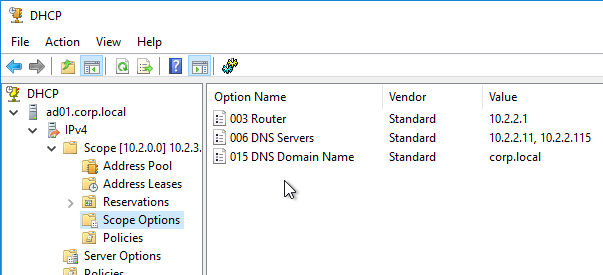
  • Global – Some data, like DNS Server addresses, apply to all scopes and thus are configured as Global DHCP Scope Options. Scope-specific DHCP Scope Options override Global DHCP Scope Options.

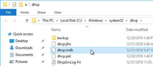
DHCP Database – DHCP scope configuration and the list of DHCP-issued IP addresses are stored in a DHCP database on each DHCP Server.

DHCP Server Redundancy – If the DHCP Server is down, then DHCP Clients cannot get an IP address when they boot, and thus can’t communicate on the network. You typically need at least two DHCP Servers.

  • DHCP Database Replication – If there are multiple DHCP Servers, then the DHCP database must be replicated. Windows Server 2012 and newer have a DHCP Scope (i.e. Database) replication capability. As do other DHCP servers like Infoblox.
  • Split Scope – If the DHCP Database is not replicated, then configure each DHCP Server with different IP Address Pools to ensure that there aren’t two DHCP Servers giving out the same IP addresses. You can take a large pool of addresses and split the pool across the DHCP Servers.

DNS (Domain Name Server)

DNS converts words to numbers – When users use a browser to visit a website, the user enters a human-readable, word-based address. However, machines can’t communicate using words, so these words must first be converted to a numeric address. That’s the role of DNS.

DNS Client – Every client machine has a DNS Client. The DNS Client talks to DNS Servers to convert word-based addresses (DNS names) into number-based addresses (IP addresses).

DNS Query – The DNS Client sends a DNS Query containing the word-based address to a DNS Server. The DNS Server sends back an IP Address. The client machine then connects to the IP Address. (image from Wikimedia)

DNS and Traffic Steering – DNS Servers have much leeway in how they choose an IP address to return in response to a DNS Query.

  • DNS Servers can be simple static databases, where the same IP address response is given every time a Query is received for a particular DNS name.
  • Or DNS Servers can be dynamic where the DNS Servers gives out different IP addresses depending on IP reachability and the client’s proximity to the IP address.

DNS Servers play an important role in Traffic Steering (aka Intelligent Traffic Management) by giving out different IP addresses based on network conditions. On Citrix ADC, the GSLB (Global Server Load Balancing) feature performs DNS Traffic Steering.

Do not overlook the importance of DNS when troubleshooting an HTTP Client connectivity problem.

DNS Servers configured on client machine – On every client machine, you specify which DNS Servers the DNS Client should use to resolve DNS names into IP addresses. You enter the IP addresses of two or more DNS Servers.

  • DHCP can deliver DNS Server addresses – These DNS Server IP addresses can also be delivered by the DHCP Server as Scope Options when the DHCP Client requests an IP address.

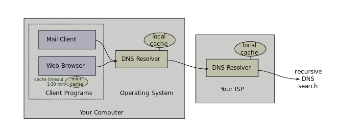
Local DNS Servers – DNS Clients do not resolve DNS names themselves. Instead, DNS Clients send the DNS Query to one of their configured DNS Servers, and the DNS Server resolves the DNS Name into an IP address. The DNS Server IP addresses configured on the DNS Client are sometimes called Local DNS Servers and/or Resolvers.

  • Recursive queries – A DNS Server can be configured to perform recursive queries. When a DNS Client sends a DNS Query to a DNS Server, if the DNS Server can’t resolve the address using its local database, then the recursive DNS Server will walk the DNS tree to get the answer. If Recursion was not enabled, then the DNS server would simply send back an error (or a referral) to the DNS client.

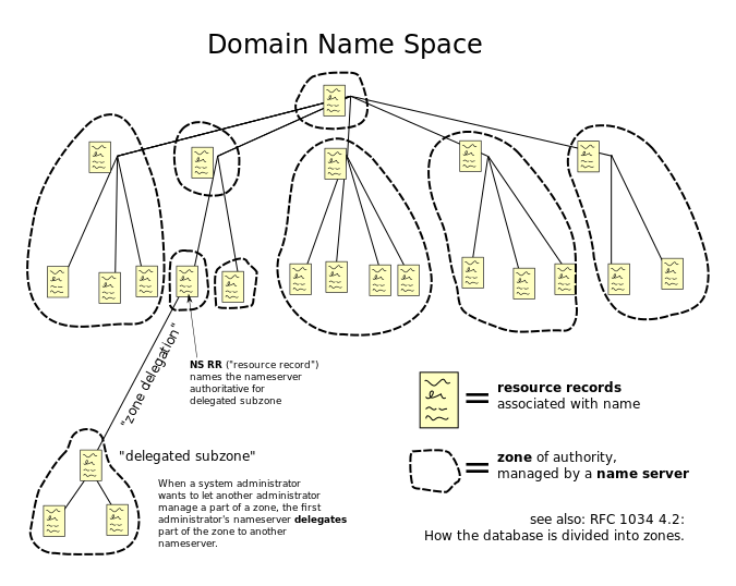
DNS scalability – The Internet has billions of IP addresses. Each of these IP addresses has a unique DNS name associated with it. It would be impossible for a single DNS server to have a single database with every DNS name contained within it. To handle this scalability problem, DNS names are split into a hierarchy, with different DNS servers handling different portions of the hierarchy. The DNS hierarchy is a tree structure, with the root on top, and leaves (DNS records) on the bottom. (image from Wikimedia)

DNS names and DNS hierarchy – A typical DNS name has multiple words separated by periods. For example, www.google.com. Each word of the DNS name is handled by a different portion of the DNS hierarchy (different DNS Servers).

Walk the DNS tree – Resolving a DNS name into an IP address follows a process called “Walk the tree”. It’s critical that you understand this process: (image from Wikimedia)

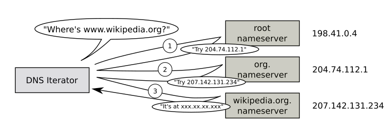
  1. Implicit period (root) – DNS names are read from right to left. At the end of www.google.com is an implicit period. So the last character of every fully qualified DNS name is a period (e.g. www.google.com.), which represents the top (root) of the DNS tree.
  2. Next is .com. The DNS recursive resolver sends a DNS Query to the parent Root DNS Servers asking for the IP Addresses of the DNS Servers that host the .com DNS zone.
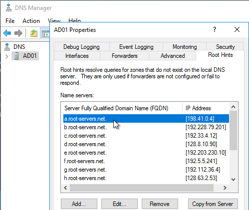
    • The DNS recursive resolver is configured with a hard coded list of DNS Root Server IP addresses, also called Root Hints.
    • The root DNS servers are usually owned and operated by government agencies, or large service providers.
    • The root DNS Servers have a link (aka delegation or referral) to the .com DNS Servers.
  3. Next is google.com. The DNS recursive resolver sends a DNS Query to the parent .com DNS Servers asking for the IP Addresses of the DNS Servers that host the google.com DNS zone.
    • The .com DNS Servers are usually owned and maintained by the Internet Domain Registrars.
    • The .com servers have a link (aka delegation or referral) to the google.com DNS Servers.
  4. Finally, the DNS recursive resolver asks the google.com DNS Servers to resolve www.google.com into an IP address.
    • The google.com DNS Servers can resolve www.google.com directly without linking or referring to any other DNS Server.

DNS Caching – Resolved DNS queries are cached for a configurable period of time. This DNS cache exists on both the Resolver/Recursive DNS Server, and on the DNS Client. The caching time is defined by the TTL (Time-to-live) field of the DNS record. When a DNS Client needs to resolve the same DNS name again, it simply looks in its cache for the IP address, and thus doesn’t need to ask the DNS Resolver Server again.

  • If two DNS Clients are configured to use the same Local DNS Servers/Resolvers, when a second DNS Client needs to resolve the same DNS name that the first DNS Client already resolved, the DNS Resolver Server simply looks in its cache and sends back the response and there’s no reason to walk the DNS tree again, at least not until the TTL expires.

DNS is not in the data path – Once a DNS name has been resolved into an IP Address, DNS is done. The traffic is now between the user’s client software (e.g. web browser), and the IP address. DNS is not in the data path. It’s critical that you understand this, because this is the source of much confusion when configuring ADC GSLB.

FQDN – When a DNS name is shown as multiple words separated by periods, this is called a Fully Qualified Domain Name (FQDN). The FQDN defines the exact location of the DNS Name in the DNS tree hierarchy.

DNS Suffixes – But you can also sometimes just enter the left word of a DNS name and leave off the rest. In this case, the DNS Client will append a DNS Suffix to the single word, thus creating a FQDN, and send the FQDN to the DNS Resolver to get an IP address. A DNS Client can be configured with multiple DNS Suffixes, and the DNS Client will try each of the suffixes in order until it finds one that works.

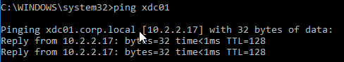
  • When you ping a single word address, ping will show you the FQDN that it used to get an IP address.

Authoritative DNS Servers – Each small portion of the DNS hierarchy/tree is stored on different DNS servers. These DNS servers are considered “authoritative” for one portion of the DNS tree. When you send a DNS Query to a DNS Server that has the actual DNS records in its configuration, the DNS Server will send back the IP Address and flag the DNS response as “authoritative”. But when you send a DNS query to a DNS Resolver that doesn’t have google.com‘s DNS records in its local database, the DNS Recursive Resolver will get the answer from google.com‘s DNS servers, and your local DNS Server flags the DNS Response as “non-authoritative”. The only way to get an “authoritative” response for www.google.com is to ask the google.com‘s DNS servers directly.

  • DNS Zones – The portion of the DNS tree hosted on an authoritative DNS server is called the DNS Zone. A single DNS server can host many DNS Zones. DNS Zones typically contain only a single domain name (e.g. google.com). If DNS records for both company.com and corp.com are hosted on the same DNS server, then these are two separate zones.
  • Zone Files – DNS records need to be stored somewhere. On UNIX/Linux DNS servers, DNS records are stored in text files, which are called Zone Files. Microsoft DNS servers might store DNS records inside of Active Directory instead of in files.

DNS records – Different types of DNS records can be created on authoritative DNS servers:

  • A (host) – this is the most common type of record. It’s simply a mapping of one FQDN to one IP address.
    • DNS Round Robin – If you create multiple Host records (A records) with the same FQDN, but each A record has a different IP address, then the DNS Server will round robin pick one of the IP Addresses for its DNS Response. Different DNS Queries will get different IP addresses in their DNS Response. This is called DNS Round Robin load balancing. One problem is that most DNS Servers do not know if the IP address is reachable or not.
  • CNAME (alias) – this record aliases one FQDN into another FQDN. To get the IP address for a CNAME FQDN, get the IP address for a different FQDN instead. See below for details.
  • NS (name server) – NS records are referrals to other DNS servers that are authoritative for a specified portion of the DNS hierarchy.
    • To delegate a FQDN or DNS sub-zone to a different DNS Server, you create NS records in the parent zone.
    • Create NS records when you need to delegate DNS resolution to Citrix ADC so Citrix ADC’s GSLB feature can intelligently resolve DNS names to multiple IP Addresses.

Resolving a CNAME – While the DNS Resolver is walking the tree, a CNAME might be returned instead of an IP address. The CNAME response contains a new FQDN. The Resolver starts walking the tree again, but this time for the new FQDN. If the DNS Resolver gets another CNAME, then it starts over again until it finally gets an IP Address. The IP Address is returned in the DNS Response to the original DNS Query.

  • Actual FQDN – The DNS Response also contains the actual FQDN that the IP address actually came from, instead of the original FQDN that was in the DNS Query.
    • If you ping the original FQDN, ping shows you the CNAME’d FQDN.
    • However, if a Web Browser performed the DNS Query, then the Web Browser ignores the CNAME’d FQDN and instead leaves the original FQDN in the browser’s address bar. This means that DNS CNAME does not cause a Browser redirect.
  • CNAMEs and Cloud – CNAMEs are used extensively in Cloud Web Hosting services. If you create a website on Azure Web Apps, Azure creates a DNS A record for the website but the A record FQDN is based on Azure’s DNS suffixes, not your DNS suffix. If you want to use your own DNS suffix, then you create a CNAME from a FQDN using your DNS suffix, to the FQDN that Azure created.

Public DNS Zones – Public DNS names are hosted on publicly (Internet) reachable DNS Servers. The same companies that provide public website hosting also provide public DNS zone hosting.

Private DNS zones – Private DNS Zones are hosted on internal DNS Servers only. Private DNS zones are used extensively in Microsoft Active Directory environments to allow domain-joined machines to resolve each other’s IP Addresses. Each Active Directory domain is a different Private DNS Zone. Private DNS zones are not resolvable from Public DNS Servers.

Private DNS Servers – When a private client (behind the firewall) wants to communicate with a private server, the private DNS Clients should send a DNS Query to a Private DNS Server, not to a public DNS Server. In Microsoft Active Directory environments, Domain Controllers are usually the Private DNS Servers.

  • Private DNS Servers can resolve Public DNS names – When a private client wants to communicate with a server on the Internet, the private DNS Client sends the DNS Query for the public DNS name to a Private DNS Server. Private DNS Servers are recursive resolvers so they can walk the Internet DNS servers to resolve public DNS names too.
    • For DNS Clients that need to resolve both Private DNS names and Public DNS names, configure the DNS Clients to only use Private DNS Servers. Do not add any Public DNS Server (e.g. 8.8.8.8) to the NIC’s IP configuration. If you do, then sometimes the DNS Client might send a DNS Query for a Private DNS name to the Public DNS Server and it won’t succeed.
  • DNS Forwarding – if a Private DNS Server does not have access to the Internet, then the Private DNS Server can be configured to forward unresolved DNS Queries to a different Private (or public) DNS Server that is configured as a Recursive Resolver.
    • DNS Tree Short Circuit – DNS Forwarding can short circuit DNS Tree walking. If a corp.com DNS server wants to resolve a company.com FQDN, then you can configure the corp.com DNS servers to forward all company.com FQDNs directly to a DNS Server that hosts the company.com DNS zone. This eliminates needing to walk the tree to find the company.com DNS Servers.
    • DNS Forwarding for Private Zones – Walking the tree usually only works for public FQDNs since the root DNS servers are public DNS servers. If you have multiple private DNS zones on different private DNS Servers, you usually have to configure DNS forwarding for each of the private zones.

Split DNS – Since Public DNS and Private DNS are completely separate DNS Servers, you can host DNS Zones with the same name in both environments. Each environment can be configured to resolve the same FQDNs to different IP Addresses. If a Private DNS Client resolves a particular FQDN through a Private DNS Server, then the IP address response can be an internal IP address. If a Public DNS Client resolves the same FQDN through a Public DNS Server, then the IP address response can be a public IP address. Internal clients resolving FQDNs to internal IP addresses avoids internal clients needing to go through a firewall to reach the servers.

Physical Networking

Layer 1 (Physical cables)

ADC appliances connect to network switches using several types of media (cables).

  • Gigabit cables are usually copper CAT6 twisted pair with 8-wire RJ-45 connectors on both sides.
  • 10 Gigabit or higher bandwidth cables are usually fiber optic cables with SC connectors on both sides.

Transceivers (SFP, SFP+, QSFP+, SFP28)

  • Transceivers convert optical to electrical and vice versa – To connect a fiber optic cable between two network ports, you must first insert a transceiver into the switch ports. The transceiver converts the electrical signals from the switch or ADC into optical (laser) signals. The transceiver then converts the laser signals to electrical signals on the other side.
  • Transceivers are pluggable – just insert them.
    • Switch ports and ADC ports only accept specific types of transceivers.
  • Different types of transceiver
    • SFP transceivers only work up to gigabit speeds.
    • For 10 Gig, you need SFP+ transceivers.
    • For 40 Gig, you need QSFP+ transceivers.
    • For 25 Gig, you need SFP28 transceivers
    • For 100 Gig, you need QSFP28 transceivers

For cheaper 10 Gig+ connections, Cisco offers Direct Attach Copper (DAC) cables:

  • Transceivers are built into both sides of the cable so you don’t have to buy the transceivers separately.
  • The cables are based on Copper Twinax. Copper means cheaper metal, and cheaper transceivers, than optical fiber.
  • The cables are short distance (e.g. 5 meters). For longer than 10 meters, you must use optical fiber instead.

Port Channels (cable bonds)

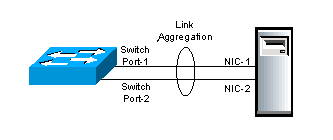
Cable Bonding – Two or more cables can be bound together to look like one cable. This increases bandwidth, and increases reliability. If you bond 4 Gigabit cables together, you get 4 Gigabit of bandwidth instead of just 1 Gigabit of bandwidth. If one of those cables stops working for any reason, then traffic can still use the other 3 cables. (image from wikipedia)

Cable Bonding does not impact network functionality – Cable bonding does not affect networking in any way. Ethernet and IP routing don’t care if there’s one cable, or if there are multiple cables bonded into a single link.

  • However, if you connect multiple unbonded cables to the same VLAN, then Ethernet and IP routing see each unbonded cable as a separate connection and this will mess up your switching and routing designs. Don’t connect multiple cables to one VLAN unless you bond those cables.

Various Names for Cable Bonding – On Cisco switches, cable bonding functionality has several names. Probably the most common name is “port channel”. Other names include: “link aggregation”, “port aggregation”, “switch-assisted teaming”, and “Etherchannel”.

Bond Both Sides – to bond cables together, you must configure both sides of the connection identically. You configure the switch to bond cables. And you configure the ADC (or server) to bond cables.

  • On ADC, the bonding feature is called Channel. On ADC, a Channel is represented by a new interface called LA/1 or something like that. LA = Link Aggregate. The 1 indicates the number of the Port Channel. An ADC can have multiple Port Channels (LA/1, LA/2, etc.), with each Channel configured for a different VLAN.

Cable Bonds have one MAC address – Each cable is plugged into a NIC port. Each NIC port has its own MAC Address. An IP Address can only be ARP’d to a single MAC address, which means the incoming traffic only goes to one of the cables. To get around this problem, when a port channel (bond) is configured, a single MAC address is shared by all of the cables in the bond, and both sides of the cable bond know that the single MAC address is reachable on all members of the cable bond.

  • If you connect two unbonded cables from one ADC to the same VLAN, then each port/cable will have its own MAC address. When a router does an ARP for an IP address that is owned by the ADC, the ARP will reach the ADC on both cables, and ADC will respond using the MAC address of each interface. Sometimes the ARP response will be for one of the MAC addresses, and sometimes the ARP response will be for the other MAC address. This results in an error called “MAC Move” and is sometimes interpreted as an IP Conflict. To avoid this problem, always bond cables that are connected to the same VLAN so that both cables will have the same MAC address.

Load Balancing across the bond members – The Ethernet switch and the ADC will essentially load balance traffic across all members of the bond. There are several port channel load balancing algorithms. But the most common algorithm is based on source IP and destination IP; all packets that match the same source IP and destination IP will go down the same cable. Packets with other combinations of source IP and destination IP might go down a different cable. If you are bonding Gigabit cables, since a single source/destination connection only goes down one cable, it can only use up to 1 Gigabit of throughput. Bonds only provide increased bandwidth if there are many source/destination combinations.

LACP – Cables can be bonded together manually, or automatically. LACP is a protocol that allows the two sides (switch and ADC) of the bonded connection to negotiate which cables are in the bond, and which cables aren’t. LACP is not the actual bonding feature; instead, LACP is merely a negotiation protocol to make bonding configuration easier.

Multi-switch Port Channels – Port Channels (bonds) are usually only supported between one ADC and one switch. To bond ports from one ADC to multiple switches, you configure something called Multi-chassis Port Channel. Multi-chassis refers to multiple switches. You almost always want multi-chassis since that lets your Port Channel survive a switch failure.

  • Virtual Port Channel – On Cisco NX-OS switches, the multi-chassis port channel feature is called “virtual port channel”, or vPC for short. When connecting a single ADC Port Channel to multiple Nexus switches, ask the network team to create a “virtual port channel”.
  • Stacked Switches – Other switches support a “stacked” configuration where multiple switches look like one switch. There are usually cables in the back of the switches that connect the switches together.

Port Channel Configuration – first, ask the switch administrator to create a port channel using multiple switch ports. The switch administrator can optionally enable LACP on the Channel. Then the ADC administrator can create a Channel on the ADC appliance.

  • Create Manual Channel On ADC – if LACP is not enabled on the switch’s port channel, then create a “manual” channel (without LACP). On the ADC, go to System > Network > Channels, create a channel, select the channel interface name (e.g. LA/2), and then add the member interfaces.
  • Create LACP Channel on ADC – if LACP is enabled on the switch’s port channel, then on the ADC, go to System > Network > Interfaces, double-click a member interface, scroll down, check the box to enable LACP, and enter a “key” (e.g. 1). All members of the same channel must have the same key. If you enter “1” as the key, then a new interface named LA/1 is created, where the “1” = the LACP key.
    • On ADC, LACP is enabled on the interface, not the Channel. There’s no need to manually create a Channel. The Chanel will be created automatically once you set the LACP Key on the member interfaces. After the Channel is automatically created on the ADC, you can Edit the Channel to see the member interfaces and make sure they are “distributing”.
    • The LACP “key” configured on the ADC does not need to match the port channel number on the switch side. ADC appliances typically have Channels named LA/1, LA/2, etc., while Switches can have port channel interfaces named po281, po282, etc.

VLAN tagging

VLAN review – Earlier I mentioned that switches can support multiple Ethernet subnets and each of these Ethernet subnets is a different VLAN. Each switch port is configured to belong to a particular VLAN. Ports in the same VLAN use Ethernet to communicate with each other. Ports in separate VLANs use routers to communicate with each other.

Multiple VLANs on one port – Switches can also be configured to allow a single switch port to be connected to multiple VLANs. An ADC usually needs to be connected to multiple subnets (VLANs). You can either assign each VLAN to a separate cable/channel, or you can combine multiple VLANs/subnets onto a single cable/channel.

VLAN tagging – If a single switch port supports multiple VLANs, when a packet is received by the switch port, the switch needs some sort of identifier to know which VLAN the packet is on. A VLAN tag is added to the Ethernet packet where the VLAN tag matches the VLAN ID configured on the switch.

  • Tags are added and removed on both sides of the switch cable – The ADC adds the VLAN tag to packets sent to the switch. The switch removes the tag and switches the packet to other switch ports in the same VLAN. When packets are switched to the ADC , the switch adds the VLAN tag so ADC knows which VLAN the packet came from.

Trunk Port vs Access Port – When multiple VLANs are configured on a single switch port (or channel), this is called a Trunk Port. When a switch port (or channel) only allows one VLAN (without tagging), this is called an Access Port. Switch ports default as Access Ports unless a switch administrator specifically configures it as a Trunk Port. Access Ports don’t need VLAN tagging, but Trunk Ports do need VLAN tagging. When you want multiple VLANs on a single switch port, ask the networking team to configure a Trunk Port.

  • Trunk Ports and VLAN ID tagging – when a switch port is configured as a Trunk Port, by default, every VLAN assigned to that Trunk Port requires VLAN ID tagging. The ADC must be configured to apply the same VLAN ID tags that the switch is expecting.
  • Trunk Ports and Native VLAN – One of the VLANs assigned to the Trunk Port can be untagged. This untagged VLAN is called the native VLAN. Only one VLAN can be untagged. Native VLAN is an optional configuration. Some switch administrators, for security reasons, will not configure an untagged VLAN (native VLAN) on a Trunk Port. If untagged VLANs are not allowed on the switch, then you must configure the ADC to tag every packet, including the NSIP. Configuring a Native VLAN on the trunk port simplifies some ADC configuration (especially NSIP and High Availability), as detailed later.

Trunk Ports reduce the number of cables – if you had to connect a different cable (or Port Channel) from ADC for each VLAN, then the number of cables (and switch ports) can quickly get out of hand. The purpose of Trunk Ports is to reduce the number of cables.

Trunk Ports and Port Channels are separate features – If you want to bond multiple cables together, then you configure a Port Channel. If you want multiple VLANs on a single cable or Port Channel, then you configure a Trunk Port. These are two completely separate features. Port Channels can be Access Ports.

Trunk Ports and Routing are separate features – Configuring a Trunk port with multiple VLANs does not automatically enable routing between those VLANs. Each VLAN on the Trunk Port is a separate Layer 2 Ethernet broadcast domain and they can’t communicate with each other without routing. Routing is configured in a separate part of the Layer 3 switch, or on a separate router device. In other words, Trunk Ports are unrelated to routing.

Multiple NICs in one machine

A single machine (e.g. ADC appliance) can have multiple NIC ports with multiple connected cables.

Single VLAN/subnet does not need VLAN configuration on the ADC – if the ADC is only connected to one subnet/VLAN, then no special configuration is needed. Just create the NSIP, SNIP, and VIPs in the one IP subnet.

  • You can optionally bond multiple cables into a Port Channel for redundancy and increased bandwidth.

Two or more NICs to one VLAN requires cable bonding – If two or more NIC ports are connected to the same VLAN, then the NIC ports must be bonded together into a Port Channel. Port Channels require identical configuration on the switch side and on the ADC side. If you don’t bond them together, then you run the risk of bridging loops and/or MAC moves.

Multiple VLANs/subnets requires VLAN configuration on the ADC – if a ADC is connected to multiple IP subnets, then the ADC must be configured to identify which subnet is on which NIC port. Here’s the configuration process:

  1. On the ADC, for each IP subnet, create a Subnet IP address (SNIP) with subnet mask for that subnet. If the ADC is connected to four IP subnets/VLANs, then you should have at least four SNIP addresses, one for each subnet.
  2. On the ADC, create a VLAN object for each IP subnet and bind each VLAN object to one network interface or Port Channel.
    • The ADC’s VLAN object asks for a VLAN ID number, and has a checkbox to indicate if the VLAN ID number is tagged or not.
  3. Bind a subnet IP address (SNIP) with subnet mask to each VLAN object so ADC knows which IP addresses are on which VLAN and by extension which network interface.

ADC VLAN objects are always required on a multi-subnet ADC, even if the switch does not need VLAN tagging – If an ADC is connected to two or more subnets, it doesn’t matter if VLAN tagging is required by the switch or not; VLAN objects (and SNIPs) still must be defined on the ADC so the ADC knows which IP subnets go with which interfaces.

ADC VLAN Tagging – On the ADC, when you create a VLAN object, you specify a VLAN ID number. This VLAN ID number can be tagged or untagged.

  • If the switch port is an access port that does not expect VLAN-tagged traffic, then the VLAN ID number entered on the ADC is only locally significant and doesn’t have to match the switch’s VLAN ID.
    • It’s easier to understand the networking configuration if the ADC’s VLAN ID and the switch port’s VLAN ID match.
  • If the switch port is a Trunk Port, then there’s a checkbox in the ADC’s VLAN object to enable tagging for this VLAN ID number.
    • The tagged VLAN ID number configured on the ADC’s VLAN object must match the tagged VLAN number configured on the switch port.
  • You can bind multiple ADC VLAN objects to a single ADC interface/channel that is connected to a switch trunk port
    • Each ADC VLAN object bound to the same Trunk Interface must be tagged.
    • Only one untagged ADC VLAN object can be bound to a Trunk Interface. The untagged VLAN will only work if the switch Trunk Port is configured with a native VLAN (untagged).

Routing table – When you create a SNIP/VLAN on a ADC, a “direct” connection is added to the routing table. You can view the routing table at System > Network > Routes. “Direct” means the ADC has a Layer 2 (ARP) connection to the IP Subnet.

One Default Route – the routing table usually has a route 0.0.0.0 that points to the Default Gateway/Router. There can only be one default route on a device even if that device is connected to multiple VLANs.. The ADC can send Layer 2 packets out any directly connected interface/VLAN, but Layer 3 packets only go out the one default route, which is on only one VLAN.

  • Add Static Routes to override Default Route – To use a different router than the default router, you add static routes to the routing table. A static route is a combination of the destination subnet you are trying to reach, and the address of the Next Hop router that can reach that destination. The Next Hop router address must be on one of the VLANs that the ADC is connected to, and is usually a different router than the default router.
  • A common use case for static routes is for an ADC appliance that is connected to both a DMZ subnet, and an internal subnet. The default router is usually a router in the DMZ that can route to the Internet. For internal networks, you add static routes for destinations to internal networks through an internal router as the next hop address.

How ADC Source IP is chosen – when a multi-subnet ADC wants to send a packet to a remote routed subnet (not directly connected), it does the following:

  1. The ADC looks in its routing table for the next hop address to reach the destination.
    • The matching routing entry can be a static route, or it can be the default route.
  2. The ADC selects one of its SNIP addresses that is on the same subnet as the next hop router address.
  3. ADC looks in its VLAN configuration to determine the network interface that is connected to the router.
    • The SNIP is bound to a VLAN object, which is bound to an interface or Channel.
  4. ADC does an ARP to get the router’s MAC address.
  5. ADC puts a packet on the wire with the subnet’s SNIP as the Source IP address and the router’s MAC address as the Ethernet destination address.
  6. Router receives the packet and routes it to the destination machine (e.g. web server).
  7. The web server responds to the Source IP in the packet, which is the ADC’s SNIP address.
  8. The web server sends the packet to its local default gateway, which routes the packet to the ADC’s SNIP address.

ADC Networking

Traffic flow through ADC

ADC-owned IP addresses – ADCs have several types of owned IP addresses: Virtual IP (VIP), Subnet IP (SNIP), NetScaler IP (NSIP), and GSLB Site IP. When you create one of these types of IP addresses on an ADC, the ADC owns that IP, which means the ADC replies to ARP requests for those IP addresses. ADC-owned IP addresses cannot be configured on any other networking device.

  • Non-ADC-owned IP addresses – When you configure an ADC to load balance web servers, you enter the IP addresses of the web servers so the ADC knows where to send the load balanced traffic. The web server IP addresses are not owned by the ADC.
  • ADCs receive traffic destined to owned IP addresses. ADCs send traffic to non-owned IP addresses.

NSIP (NetScaler IP) is the ADC’s management IP address. ADC administrators connect to the NSIP to manage the ADC appliance.

VIPs (Virtual IP) – VIPs receive traffic. When you create a Virtual Server (e.g. Load Balancing Virtual Server), you specify a Virtual IP address (VIP) that clients connect to.

  • You also specify a port number for the Virtual Server to listen on. The ADC drops traffic that is not destined to the specified port number.

SNIPs (Subnet IP) – SNIPs are the Source IP addresses that ADC uses when ADC sends traffic to a web server. When ADC appliances need to send a packet, they look in the routing table for the next hop address and select a SNIP on the same subnet as the next hop. The Source IP address of the request packet is set to the SNIP. Web servers reply to the SNIP.

The following image is from the ADC Welcome Wizard when configuring a SNIP.

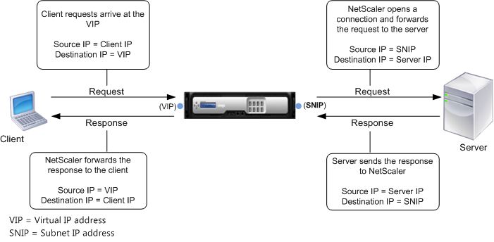
Load Balancing traffic overview – here’s a simplified description of ADC Load Balancing:

  • VIP/Virtual Server – Clients send traffic to a Load Balancing VIP.
  • Services – Bound to the Load Balancing Virtual Server are one or more Load Balancing Services (or Service Group). These Load Balancing Services define the web server IP addresses and the web server port number. ADC chooses one of the Load Balancing services, and forwards the HTTP request to it.
    • ADC replaces with the source IP with one of its SNIPs. The Web Servers reply to the SNIP.
  • Monitors – ADC should not send traffic to a web server unless that web server is healthy. Monitors periodically send health check probes to web servers.

ADC Source IP and Logging

ADC SNIP replaces original Client IP – When ADC communicates with a back-end web server, the original source IP address is replaced with an ADC SNIP. The web server does not see the original Client IP address. This behavior is sometimes called Source NAT.

If SNIP is the source IP, how can web servers log the original Client IP? – Since web servers behind a ADC only see the ADC’s SNIP, the HTTP request entries in the web server access logs (e.g. IIS log) all have the same ADC SNIP as the client IP. If the web server needs to see the real Client IP, then ADC provides three options:

  • Client IP Header Insertion – when you create a Load Balancing Service on the ADC, there’s a checkbox to insert the real client IP into a user-defined HTTP Header. This HTTP Header is typically named X-Forwarded-For, or Real IP, or Client IP, or something like that. The web server then needs to be configured to extract the custom HTTP header and log it. The packets on the wire still have an ADC SNIP as the Source IP.
  • Use Source IP (USIP) – The default mode for ADC is Use Subnet IP (USNIP), which replaces the original Client IP address with ADC SNIP address. This mode can be changed to Use Source IP (USIP), which leaves the original Source IP (Client IP) in the packets. When web servers respond, they send the reply to the Client IP, and not to the ADC SNIP. If the Response does not go through the ADC , then ADC is only seeing half of the conversation, which breaks many ADC features. If you need USIP mode, then reconfigure the web server’s default gateway to point to a ADC SNIP. When the web server replies to the Client IP, it will send the reply packet to its default gateway, which is a ADC SNIP, thus allowing ADC to see the entire conversation.
    • USIP can be enabled globally for all new Load Balancing Services, or can be enabled on specific Load Balancing Services, so you can use SNIP for some web servers and USIP for others.
    • If a web server’s default gateway is an ADC SNIP, then all outbound traffic from web server, including general Internet traffic, will go through the ADC. The ADC must have a sufficient bandwidth license to handle this traffic.
    • USIP tends to complicate ADC network configurations, so avoid it if you can.
  • Direct Server Return (DSR) – An option similar to USIP is Direct Server Return (DSR). DSR does not need the web server to change its default gateway so reply traffic bypasses the ADC and doesn’t eat up the ADC’s bandwidth license. DSR is typically used for SMTP Load Balancing so SMTP Servers can filter messages based on real client IP addresses. However, DSR is a complicated configuration that requires the addition of loopback adapters to the destination servers.

ADC Forwarding Tables

ADC has at least three tables for choosing how to forward (route) a packet. They are listed below in priority order. MBF overrides PBR, which overrides routing table.

  • Mac Based Forwarding (MBF) – MBF keeps track of which interface/router a client request came in on and replies out the same interface/router. Only works for replies and doesn’t do anything for ADC-initiated connections. Since it overrides routing tables, MBF is usually discouraged.
  • Policy Based Route (PBR) – Normal routing only uses destination IP to choose the next hop router. PBRs can choose a next hop address based on packet fields other than just Destination IP. These other packet fields include: source IP, source port, and destination port. PBRs are difficult to maintain and thus most networking people try to avoid them, but they are sometimes necessary (e.g. dedicated management network).
  • Routing Table – the routes in the routing table come from three sources: SNIPs (directly connected subnets), manually-configured Static Routes (including default route), and Dynamic Routing (OSPF, BGP).

ADC networking configuration vs Server networking configuration

ADC networking is configured completely differently than server networking. ADC is configured like a switch, not like a server.

  • Servers assign IPs to NICs – On servers, you configure an IP address directly on each NIC. Most servers only have one NIC.
  • ADC appliances are configured like a Layer 3 Switch – On ADC appliances, you assign VLANs to interfaces, just like you do on a switch. Then you put ADC-owned IP addresses into each of those VLANs, which again, is just like a Layer 3 switch. More specifically, you create VLAN objects, bind the VLAN to an interface/channel, and then bind a SNIP to the VLAN.

ADC VLAN Design

ADC VLAN Options:

  • VIP VLANs – The ADC must be Layer 2 connected to any VLAN that hosts ADC VIPs (Load Balancing VIPs, Citrix Gateway VIPs, etc.)
    • Security zones – Ideally, an ADC’s VIPs should only be hosted in one security zone (e.g. DMZ only). If you need to host VIPs in multiple security zones (e.g. both DMZ and internal), then you should acquire separate ADC appliances for each security zone.
    • Route Partitioning – Citrix ADC has several technologies that can split the ADC’s single routing table into multiple routing tables. These features include: Traffic Domains, Administration Partitioning, Net Profiles, and ADC SDX multi-tenant appliances. However, each of these features has cons. See the Firewalls section below for details.
  • Dedicated management VLAN? – Dedicated management VLAN means that only the ADC NSIP (management IP) is placed on this VLAN. Don’t put any VIPs on this management VLAN. Don’t put any SNIPs on this management VLAN. If no VIPs or SNIPs, then the management VLAN cannot be used for incoming or outgoing data traffic (e.g. load balancing traffic).
    • Citrix ADC does not have a true management interface – a management interface should have its own default gateway/route that is separate from the data plane’s default route. And there should be no possibility of data traffic ever going out the management interface. Unfortunately, Citrix ADC does not support this. Alternatively, we can configure PBRs or MBF to simulate a dedicated management network, but be aware that this is simply configuration and is not enforced in hardware. For details, see Dedicated Management Subnet (PBRs).
  • Server VLANs – If the ADC can route from a VIP VLAN to the web servers, then there’s usually no need to connect the ADC directly to the web server VLANs. Most core routing is performed at wire speed so there’s no performance benefit to connecting the ADC to the server VLANs.
    • Advanced load balancing configurations like Use Source IP (USIP) and Direct Server Return (DSR) do require the ADC to be connected directly to the server VLANs.
    • Security zones – if the VIPs are hosted in a DMZ VLAN, and if you connect the ADC directly to an internal server VLAN, then there is very high risk of bypassing a firewall. Client traffic reaches the ADC through the VIPs. The ADC uses an internal SNIP to communicate with the web servers. The VIP and the SNIP are in two different security zones.

ADC Physical Connectivity

Interface 0/1 is only for management – Dedicated management VLANs are usually connected to interface 0/1 on the ADC . If you don’t have a dedicated management VLAN, then don’t use interface 0/1 on physical ADC appliances and instead, use interfaces 1/1 and higher. That’s because interface 0/1 is not optimized for high-throughput traffic.

One subnet for everything? – if the ADC is only connected to a single subnet, then the NSIP, VIPs, and SNIP will all be on one VLAN.

  • Connect two or more of the non-0/1 interfaces to two or more switches. Don’t connect anything to the 0/1 interface.
  • Bond the two data interfaces into a port channel (preferably multi-switch port channel). For configuration details, see Port Channels on Physical ADC.
  • Configure the switch’s port channel as an access port with a single VLAN.
  • On the ADC, there’s no need for any VLAN configuration.

Dedicated Management VLAN? – One option is to configure the management VLAN on its own Gigabit cable connected to the 0/1 interface on the ADC. The switch port should be an access port for the management VLAN.

Another option is to add the management VLAN to a trunk port.

  • The trunk port can be 10 Gig or higher instead of limited to the Gigabit of interface 0/1. And the trunk port is usually a port channel.
  • Can the switch trunk port be configured with the management VLAN as the native VLAN (untagged)? If so, this simplifies the ADC NSIP and ADC High Availability configuration.
  • If the management VLAN is tagged, then Citrix ADC requires NSVLAN configuration and tagging of High Availability heartbeat packets.

NSIP is special – NSIP (the management IP) lives in VLAN 1. If you don’t need to tag the management VLAN, then leave NSIP in VLAN 1. VLAN 1 on the ADC does not need to match any VLAN configured on the switch because you’re not tagging the NSIP packets with the VLAN ID. When you bind untagged VLANs to ADC interfaces, those interfaces are removed from VLAN 1 and put in other VLANs. The remaining interface in VLAN 1 is your management interface.

  • NSVLAN – if your management VLAN is tagged, then normal VLAN tagging configuration won’t work for the NSIP VLAN. Instead, you must configure NSVLAN to tag the NSIP/management packets with the VLAN ID. All other VLANs are configured normally.

Link Redundancy – for each VLAN, connect at least two cables, preferably to different switches, and then bond the cables together into a port channel.

  • Trunk Port – You can create a separate port channel for each VLAN. Or you can combine multiple VLANs onto the same port channel by configuring a Trunk Port.
  • LACP – if your port channels have LACP enabled on the switch, then on the ADC go to System > Network > Interfaces, edit two or more member interfaces, check the box for LACP, and enter the same LACP Key. If you enter 1 as the key, then a channel named LA/1 is created.
  • For manual port channels, go to System > Network > Channels, add a channel, select LA/1 or similar, and bind the member interfaces.

Disable unused Interfaces – if a ADC interface (NIC) does not have a connected cable, then disable the interface (System > Network > Interfaces, right-click an interface, and Disable). If you don’t disable the unused interfaces, then High Availability (HA) will think the interfaces are down and thus failover.

ADC VLAN Configuration

SNIPs – every VLAN needs a VLAN-specific SNIP address, except the dedicated management VLAN. If you don’t put a SNIP on the dedicated management VLAN, then the dedicated management VLAN should not be used for outbound traffic.

  • One subnet – If the ADC is only connected to one subnet, then you only need one SNIP for the entire appliance, and there’s no need to perform any ADC VLAN configuration.

NSIP VLAN – if your NSIP VLAN (management VLAN) is untagged, then you do not need to create a VLAN object for the NSIP VLAN since the ADC is already configured with VLAN 1.

  • If your NSIP VLAN is also used for data traffic, then create a SNIP in the NSIP VLAN.
  • If your NSIP VLAN needs to be tagged, then configure NSVLAN instead of the normal VLAN configuration.

VLANs – If the ADC is connected to multiple VLANs:

  1. Create a SNIP for each VLAN (except the dedicated management VLAN).
  2. Create a VLAN object for each VLAN (except the NSIP VLAN), and specify the same VLAN ID as configured on the switch.
    • It doesn’t matter if the VLAN is tagged or not, you still must create a separate ADC VLAN object for each subnet.
  3. Bind a VLAN object to one interface or channel.
  4. If the switch needs the VLAN to be tagged, then check the box to tag the packets with the specified VLAN ID.
  5. Bind the VLAN object to the SNIP for that VLAN.

Static Routes – Add static routes for internal subnets through an internal router on a “data” VLAN (not the dedicated management VLAN).

NSIP Replies – do not adjust the default route of the appliance until you configure the appliance to route NSIP replies properly. When an administrator connects to the NSIP to manage the appliance, the administrator was probably routed through a router on the NSIP VLAN. If you change the appliance’s default router to a DMZ router, then NSIP replies will go out the Internet and will never make it back to the administrator. ADC has a few options for routing these NSIP replies correctly.

  • NSIP is not on a dedicated management VLAN – in this case, the NSIP is on one of the data VLANs and you should already have static routes for internal destinations through a router on the internal data VLAN.
  • NSIP is on a dedicated management VLAN – the static routes for internal IP addresses result in NSIP replies going out the wrong interface, resulting in asymmetric routing. Or the ADC might not be connected to an internal VLAN and thus the NSIP replies go out the default DMZ (Internet-facing) router. To handle this scenario, configure one of the following on the ADC:
    • Policy Based Route – Configure a Policy Based Route (PBR) that looks for NSIP as Source IP and uses a management VLAN router as the next hop. Only packets with NSIP as source will go out the management VLAN router. All other packets will use the appliance’s routing table to look up the next hop address.
      • NSIP as source IP – some ADC features use NSIP as the source IP. These ADC features include: NTP, SNMP, Syslog, etc. PBRs properly route this NSIP-sourced traffic too.
    • Mac Based Forwarding (MBF) – MBF records which interface a packet came in on, and replies out the same interface, bypassing the routing table.
      • MBF is easy to configure, but MBF doesn’t do anything for the ADC features that initiate connections using NSIP as the source IP.

Change Default Route to DMZ router – The Default Router should be on a data VLAN (e.g. DMZ VLAN) and not on the NSIP VLAN. Now that NSIP replies and Static Routes are configured, you can probably safely delete the default route (0.0.0.0) and recreate it without you losing connection to the NSIP.

Layer 2 Troubleshooting – To verify VLAN connectivity, log into another device on the same VLAN (e.g. router/firewall) and ping the ADC SNIP or NSIP. Immediately check the ARP cache to see if a MAC address was retrieved for the IP address. If not, then layer 2 is not configured correctly somewhere (e.g. wrong VLAN configuration), or there’s a hardware failure (e.g. bad switch port).

Layer 3 Troubleshooting – There are many potential causes of Layer 3 routing issues. A common problem is incorrect Source IP chosen by the ADC. To see the Source IP, SSH to the ADC’s NSIP, run shell, and then run nstcpdump.sh host <Destination_IP>. You should see a list of packets with Source IP/Port and Destination IP/Port. Then work with the firewall and routing teams to troubleshoot packet routing.

ADC High Availability (HA)

HA Pair – You can HA pair two identical ADC appliances. The two appliances must be identical hardware, identical firmware version, and identical licensed edition.

HA and ARP – In an HA pair, each node has its own NSIP, but all of the other ADC-owned IP addresses float between the two appliances. More specifically, when there are ARP requests for VIPs and SNIPs, the primary appliance replies with its MAC addresses, but the secondary appliance does not reply to ARP requests. After an HA failover, the former secondary appliance starts responding to VIP and SNIP ARP requests with its MAC addresses, and the former primary appliance stops responding to ARPs.

  • ARP Caching and Gratuitous ARP (GARP) – When an HA pair fails over, the new primary appliance performs a Gratuitous ARP. GARP tells routers to update their ARP cache to map IP addresses to the new appliance’s MAC address instead of the old appliance’s MAC address.
    • Some routing devices (e.g. firewalls) will not accept GARP packets, and instead will wait for the ARP cache entry to time out. Or the router/firewall might not allow the IP address to move to a different MAC address. If HA failover stops all traffic, then work with the router/firewall admin to troubleshoot GARP and ARP cache.

HA monitored interfaces:

  • Disable unused interfaces – All network interfaces on ADC by default have HA monitoring enabled. If any enabled interface is down (e.g. cable not connected), then HA will failover. Disable the unused interfaces so HA won’t monitor them any more.
    • Disabling unused interfaces also stops the flashing of the front LCD.
  • Port Channels and HA failover – A port channel has two or more member interfaces. If one of the member interfaces is down, should the appliance failover? How many member interfaces must fail before HA failover should occur? On ADC, double-click the channel and you can specify a minimum throughput. If bonded throughput falls below this number due to member interface failure, then HA fails over.
  • HA Fail Safe – If at least one interface is down on both HA nodes, then both HA nodes will be unhealthy and both nodes will stop responding. You can enable HA Fail Safe so that at least one of the HA nodes will be up, even if both nodes are unhealthy.

HA heartbeat packets are untagged – Each node in a HA pair sends heartbeat packets out all interfaces. These heartbeat packets are untagged. If the switch does not allow untagged packets (i.e. no native VLAN on a Trunk Port), then some special configuration is required.

  1. On ADC, for each Trunk interface/channel, turn off tagging for one VLAN. Don’t worry about the switch configuration. Just do this on the ADC side.
  2. On ADC, go to System > Network > Interfaces (or Channels), double-click the interface/channel, and enable Tag All VLANs. The VLAN you untagged in step 1 will now be tagged again. As a bonus, HA heartbeat packets will also be tagged with the same VLAN ID you untagged in step 1.
  3. To verify that HA heartbeats are working across all interfaces, SSH to each ADC node, and run show ha node. Look for “interfaces on which HA heartbeat packets are not seen”. There should be nothing in the list.

Firewalls

DMZ – public-facing ADC VIPs should be on a DMZ VLAN that is sandwiched between two firewalls. That means the public-facing ADC must be connected to the DMZ VLAN.

  • Firewalls can route – When you connect a ADC to a DMZ VLAN, the firewall is usually the router.
  • NAT – Most DMZ VLANs use private IPs (10.0.0.0/8, 172.16.0.0/20, 192.168.0.0/16) instead of public IPs. These private IP addresses are not routable across the Internet. To make the VIPs accessible to the Internet, a firewall NATs a company-owned public IP to the private DMZ IP. Ask the firewall administrator to configure the NAT translations for each publicly-accessible DMZ VIP.
  • ADC VIPs listen on specific port numbers – the public-facing firewall only needs to allow specific port numbers to reach the public-facing VIPs. For web server load balancing, these ports are usually TCP port 80 and TCP port 443, and sometimes UDP 443.

Internal VIPs – internal VIPs (accessed by internal users) should be on an internal VLAN (not in the DMZ).

Multiple security zones – If you connect a single ADC to both DMZ and Internal, here’s how the traffic flows:

  1. Clients connect to DMZ VIPs, which goes through the firewall that separates the Internet from the DMZ.
  2. ADC internal SNIP connects to internal server. Since the ADC is connected directly to the Internal network, ADC will use an internal SNIP for this traffic. If you have a firewall between DMZ and internal, that firewall has now been bypassed.

Separate ADC appliances for DMZ and internal – Bypassing the DMZ-to-internal firewall is usually not what security teams want. Ask your Security team for their opinion on this architecture. A more secure approach is to have different ADC appliances for DMZ and internal. The DMZ appliance is connected only to DMZ (except dedicated management VLAN). When the DMZ ADC needs to communicate with an internal server, the DMZ ADC uses a DMZ SNIP to send the packet to the DMZ-to-internal firewall. The DMZ-to-internal firewall inspects the traffic, and forwards it if the firewall rules allow. The firewall rule allows the DMZ SNIP to talk to the web server, but the firewall does not allow client IPs (on the Internet) to talk directly to the web server.

Traffic Isolation – ADC has some features that can isolate/partition traffic so that the ADC traffic stays in its security zone.

  • Net Profiles – Net Profile selects a particular SNIP to be used by a Virtual Server, or Service, for traffic to back-end servers.
    • If your appliance has multiple SNIPs, create a Net Profile for each SNIP. Then bind the Net Profiles to Virtual Servers and/or Services.
    • Firewalls can permit different SNIPs to access different web servers. The firewall can allow one Virtual Server with one Net Profile to access specific internal servers, and the firewall can allow a different Virtual Server with a different Net Profile to access a different set of internal servers. The list of accessible servers for each SNIP is enforced at the firewall. However, it’s the ADC administrator’s responsibility to ensure that each Virtual Server has the correct Net Profile assigned.
    • If your ADC has multiple SNIPs on one VLAN that can reach a web server, then ADC will round robin across those SNIPs, which is very annoying for firewall configuration. It’s not possible to tell ADC to not use a SNIP unless that SNIP is in a Net Profile. To stop the round robin behavior, you must quickly assign Net Profiles (each with one SNIP) to every Virtual Server on the ADC appliance.
  • Traffic Domains – Citrix ADC supports Traffic Domains, which are similar to Cisco VRF (Virtual Route Forwarding). Traffic Domains split an ADC into multiple routing tables, which theoretically can prevent traffic from one security zone from crossing into another security zone.
  • Administrative Partitions – you carve up an MPX/VPX appliance into different administrative partitions, with each partition having access to a subset of the hardware. Each partition is essentially a separate ADC config, which means separate routing tables. VLANs can be dedicated to a partition, or VLANs can be shared across multiple partitions.
  • ADC SDX – SDX appliances carve up physical hardware into multiple virtual machines. Each VM is a full ADC VPX, each with its own configuration and own partitioned hardware (dedicated CPU, Memory, and NICs). There are no ADC feature limitations.

Network firewall (Layer 4) vs ADC Web App Firewall (Layer 7) – Most network firewalls only filter on port numbers and IP addresses, meaning that Layer 4 firewalls usually don’t inspect the traffic and instead simply permit traffic that is destined to specific port numbers.

HTTP Content Inspection – As you read earlier, HTTP is a file transfer protocol. Sometimes file uploads contain malicious content (e.g. viruses), or file downloads contain private content (e.g. credit card numbers). You probably want a firewall that can block malicious HTTP traffic. Layer 4 firewalls do not inspect the HTTP traffic and thus a Layer 4 firewall cannot protect your websites. That leaves website security as a responsibility of the web server administrator and developer.

Web App Firewalls – Layer 7 firewalls, also called Web App Firewalls (WAF), can inspect HTTP traffic and block HTTP packets that match string patterns. These matching string patterns usually come from a signature rules list.

  • Signatures – some string patterns should always cause an HTTP Request to be blocked every time the string pattern is seen in an HTTP Request. These malicious string patterns come from security firms that have identified hackers using these strings to exploit vulnerabilities in web server software. Snort is a popular provider of these string patterns.
  • OWASP Top 10 Security Checks – Web App Firewalls have additional protections for the OWASP Top 10 Most Critical Web Application Security Risks. These include: SQL Injection, Cross Site Scripting, Forceful Browsing, Buffer Overflows, etc. A WAF can block any HTTP Packet that matches these security risks, however, these blocks might break a web application’s functionality. In that case, WAF can either disable a signature rule, or relax a protection category for specific URLs.
    • Learning Mode and Relaxations – WAFs have a Learning mode where they log all HTTP traffic that would have been blocked by protection rules. The learned violations for specific URLs can be deployed as firewall relexations, just like you would permit a port number through a Layer 4 firewall. Any relaxation places the onus of security on the web server instead of on the WAF.

Citrix ADC WAF – Citrix ADC Premium Edition has a WAF feature. Here’s a brief configuration summary:

  1. Configure the web site traffic to flow through an ADC Load Balancing Virtual Server.
  2. Create an ADC WAF Signatures Object based on Snort rules.
  3. Create an ADC WAF Profile and enable various HTTP and XML security checks.
    • Enable security check Learning Mode.
  4. Create an ADC WAF Policy for the WAF Profile and then bind the WAF Policy to the Load Balancing Virtual Server.
  5. Send test traffic through the Load Balancing Virtual Server so the ADC can learn the WAF violations.
  6. Review the list of learned violations and deploy the legitimate ones as WAF relaxations. Test again.
  7. After testing, reconfigure the WAF Profile to enable enforcement. WAF will start blocking malicious HTTP traffic.

Put network firewalls in front of ADC – ADC is not designed as a Layer 4 firewall like a Cisco ASA, Check Point, or Palo Alto. Thus you should always put a network firewall in front of your ADC, even if you enabled the ADC WAF feature.

Next Step

nFactor Authentication – NetScaler Gateway 12 / Citrix Gateway 12.1

Last Modified: Apr 16, 2021 @ 2:32 pm

Navigation

💡 = Recently Updated

Change Log

nFactor Overview

nFactor lets you configure an unlimited number of authentication factors. You are no longer limited to just two factors.

Each authentication factor performs the following tasks:

  1. Collect credentials from the user. These credentials can be anything supported by Citrix ADC, including:
    • SAML assertion
    • Client Certificate
    • OAuth OpenID Connect
    • Kerberos ticket
    • StoreFrontAuth – authentication is delegated to Citrix StoreFront
    • Forms-based authentication (traditional web-based logon page) for LDAP, RADIUS, etc.
      • Multiple passwords can be collected with one form.
      • Or prompt the user multiple times throughout the authentication chain.
      • The logon page can contain a domain drop-down.
    • Endpoint Analysis Scan – either pre-authentication, or post-authentication.
    • EULA
    • Google reCAPTCHA
    • Swivel
    • Use a drop-down to select an authentication method
  2. This factor’s credentials are evaluated. The results can be:
    • Authentication success
    • Authentication failure
    • Group extraction
    • Attribute extraction from SAML, Certificate, etc.
  3. Based on the evaluation results, do one of the following:
    • Allow access
    • Select next factor
    • Deny access
  4. If there’s a Next Factor, repeat these steps, until there are no more Next Factors to evaluate.
  5. The Next Factor can also do one of the following:
    • Prompt the user for more credentials
    • If the Login Schema asked for multiple passwords, evaluate the already entered next set of credentials.
    • Use a policy expression to select another Next Factor (no authentication). This is typically used with group extraction so that groups determine the Next Factor.

Here are some nFactor use cases, but the combinations are almost limitless:

  • Choose Authentication method based on Active Directory group: Logon screen asks for user name only. Extract user’s groups from Active Directory. Based on user’s Active Directory groups, either ask user for client certificate, or ask user for LDAP password. If LDAP, the username doesn’t need to be entered again.
  • Ask for Certificate first:
    • If client certificate is valid, perform LDAP only.
    • If no client certificate, perform LDAP + RADIUS
  • Two-factor with passwords checked in specific order: Display logon screen with two password fields. Check the first password. If the first password succeeds, then check the second password. This lets you check RADIUS before LDAP.
  • Run Endpoint Analysis first:
    • If passes, perform LDAP only.
    • If fails, perform LDAP + RADIUS
  • See Sample Configurations later for many more combinations.

All new authentication methods added to Citrix ADC require nFactor configuration and are not supported on native Citrix Gateway. These new authentication methods include:

nFactor is a AAA feature, which means you need Citrix ADC Advanced Edition (aka NetScaler Enterprise Edition) or Citrix ADC Premium Edition (aka NetScaler Platinum Edition). Citrix ADC Standard Edition and Citrix Gateway VPX are not entitled for nFactor.

Citrix ADC supports two types of authentication policies – Classic, and Advanced (aka Default). You can bind Classic Authentication Policies directly to Citrix Gateway Virtual Servers, but today you cannot bind Advanced Authentication Policies to Citrix Gateway. The only way to use Advanced Authentication Policies with Citrix Gateway is to configure nFactor on a AAA Virtual Server and then link the AAA Virtual Server to the Gateway Virtual Server.

  • Workspace app 1809 and newer with Citrix Gateway (NetScaler) 12.1 build 49 and newer support nFactor authentication. Older Receivers and older NetScalers don’t support nFactor, so you’ll instead have to use a web browser.

nFactor configuration summary (detailed instructions below):

  • Each factor is a combination of Advanced Authentication Policies and Login Schema.
    • Advanced policy means it uses an Advanced (Default Syntax) expression as opposed to the classic syntax expression traditionally used in Citrix Gateway authentication policies.
    • Login Schema is a custom HTML form where users enter credentials.
  • The first factor (Advanced Authentication Policies and Login Schema) is bound directly to a AAA Virtual Server.
  • Next factors are bound to Authentication Policy Labels. These Labels are then chained to Advanced Authentication Policies in prior factors.
    • AAA vServer > Advanced Authentication Policy > Next Factor > Authentication Policy Label > Advanced Authentication Policy > Next Factor > Authentication Policy Label > … until there are no more Next Factors configured.
  • Authentication Profile links AAA vServer with Citrix Gateway.

Also see:

This article will detail how to configure nFactor from top to bottom.:

  1. Create AAA vServer
  2. Create Login Schema Profiles
  3. Create Login Schema Policy – select Login Schema Profile, bind Login Schema Policy to AAA vServer
  4. Create Authentication Actions – LDAP, RADIUS, etc.
  5. Create Advanced Authentication Policies – select Authentication Action, bind Advanced Authentication Policy to AAA vServer
  6. Create Authentication Policy Labels – bind Login Schema, bind Advanced Authentication Policies
  7. Edit Advanced Authentication Policy binding and select Next Factor Authentication Policy Label.
  8. Create Citrix Gateway Traffic Policy for Single Sign-on to StoreFront.
  9. Create Authentication Profile
  10. Edit Citrix Gateway – bind Authentication Profile, bind Traffic Policy

Once you are familiar with nFactor, due to the way the objects are linked together, it’s probably easier to configure it from bottom up:

  1. Create Authentication Actions – LDAP, RADIUS, etc.
  2. Create Advanced Authentication Policies – select Authentication Action
  3. Create Login Schema Profiles
  4. Create Authentication Policy Labels – bind Login Schema, bind Advanced Authentication Policies
  5. Create Login Schema Policy – select Login Schema Profile
  6. Create AAA vServer – bind Login Schema, bind Advanced Authentication Policies, select Next Factor Authentication Policy Label
  7. Create Citrix Gateway Traffic Policy for Single Sign-on to StoreFront.
  8. Create Authentication Profile
  9. Edit Citrix Gateway – bind Authentication Profile, bind Traffic Policy

It can be difficult to visualize a nFactor configuration so my ADC Virtual Server Configuration Extractor script now includes a nFactor visualizer. Here’s an example for a Native OTP configuration.

AAA Virtual Server

Create AAA Virtual Server

To use nFactor with Citrix Gateway, you first configure it on a AAA Virtual Server. Then you later link the AAA Virtual Server to the Citrix Gateway Virtual Server.

  1. If AAA feature is not already enabled, on the left menu, expand Security, right-click AAA – Application Traffic, and click Enable Feature.
  2. Go to Security > AAA > Virtual Servers.
  3. On the right, click Add.
  4. Give the Virtual Server a name.
  5. If you are only using this AAA Virtual Server for Citrix Gateway, then you can change the IP address Type to Non Addressable. It’s also possible to content switch to AAA (Citrix CTX201949 One Public IP for AAA-TM Deployments on NetScaler).
  6. Click OK.
  7. In the Certificates section, click where it says No Server Certificate.

    1. Click where it says Click to select.
    2. Click the radio button next to a certificate for the AAA Virtual Server, and click Select. Since this AAA Virtual Server is not directly addressable, the chosen certificate doesn’t matter.
    3. Click Bind.
  8. Click Continue to close the Certificate section.
  9. You probably don’t have any Advanced Authentication Policies yet, so just click Continue.

Bind Portal Theme to AAA Virtual Server

If this AAA Virtual Server is used not just for Citrix Gateway but also directly addressable for traffic management (Load Balancing, Content Switching), then you might want to change the AAA Portal theme.

  1. Go to Citrix Gateway > Portal Themes, and add a theme. You create the theme under Citrix Gateway, and then later bind it to the AAA Virtual Server.
  2. Create a theme based on the RfWebUI Template Theme.
  3. After adjusting the theme as desired, at the top of the portal theme editing page, Click to Bind and View Configured Theme.
  4. Change the selection to Authentication.
  5. Use the Authentication Virtual Server Name drop-down to select the AAA Virtual Server, and click Bind and Preview. You can close the preview window.

Client Certificate Authentication

If one of your authentication Factors is client certificate, then you must perform some SSL configuration on the AAA Virtual Server:

  1. Go to Traffic Management > SSL > Certificates > CA Certificates, and install the root certificate for the issuer of the client certificates. Root certificates do not have a key file.

  2. Go to Traffic Management >SSL > Change advanced SSL settings.

    1. Scroll down. If you see Default Profile: ENABLED, then you must use an SSL Profile to enable Client Certificate Authentication. Otherwise, you can enable Client Certificate Authentication directly on the AAA Virtual Server in the SSL Parameters section.
  3. If Default SSL Profiles are enabled, then create a new SSL Profile with Client Authentication enabled:
    1. On the left menu, expand System, and click Profiles.
    2. On the top right, switch to the SSL Profile tab.
    3. Right-click the ns_default_ssl_profile_frontend profile, and click Add. This copies settings from the default profile.
    4. Give the Profile a name. The purpose of this profile is to enable Client Certificates.
    5. Scroll down and find the Client Authentication checkbox. Check the box.
    6. Change the Client Certificate drop-down to OPTIONAL.
    7. Copying the default SSL Profile does not copy the SSL Ciphers so you’ll have to redo them.
    8. Click Done when done creating the SSL Profile.
    9. Go to Security > AAA – Application Traffic > Virtual Servers, and edit a AAA vServer.
    10. Scroll down to the SSL Profile section and click the pencil.
    11. Change the SSL Profile drop-down to the profile that has Client Certificates enabled. Click OK.
    12. Scroll down this article until you reach the instructions to bind the CA certificate.
  4. If default SSL Profiles are not enabled:
    1. Go to Security > AAA > Virtual Servers, and edit an existing AAA Virtual Server.
    2. On the left, in the SSL Parameters section, click the pencil icon.
    3. Check the box next to Client Authentication.
    4. Make sure Client Certificate drop-down is set to Optional, and click OK.
  5. On the left, in the Certificates section, click where it says No CA Certificate.
  6. Click to select.
  7. Click the radio button next to the root certificate for the issuer of the client certificates, and click Select.
  8. Click Bind.

Login Schema

Login Schema XML File

Login Schema is an XML file providing the structure of forms-based authentication logon pages.

nFactor implies multiple authentication Factors that are chained together. Each Factor can have different Login Schema pages/files. In some authentication scenarios, users could be presented with multiple logon screens.

Or you can have one Login Schema gather information that can be passed on to multiple Factors, so that the later Factors don’t need to display another Login Schema. This is particularly useful for traditional two-password logon screens (LDAP + RADIUS), since each password is evaluated in a separate Factor:

  • The first password is evaluated in the first factor (e.g. LDAP). If successful, then proceed to the second factor.
  • The second factor (e.g. RADIUS) evaluates the second password. However, the second password has already been entered, so there’s no need to ask the user for it again. To prevent a Login Schema from being shown to the user, select noschema (LSCHEMA_INT) in the Authentication Policy Label.

Several Login Schema .xml files are included with Citrix ADC under /nsconfig/loginschema/LoginSchema.

You can edit the Login Schema labels from within the Citrix ADC management GUI. When the labels are changed, Citrix ADC copies the Login Schema to a new .xml file based on the Schema Name entered in this widow, or based on the original file name.

Or you can use WinSCP to connect to the appliance, duplicate one of the existing .xml files, and edit it as desired. For example, you can configure fields (InitialValue tag) to pre-fill information from previous Factors, as shown below:

The structure of the Login Schema is documented at Citrix Common Authentication Forms Language Citrix Developer Documentation.

CTP Sam Jacobs at SYN229 – nFactor and Login Schemas explains how to customize the .xml file.

The login schema can also contain a domain drop-down. See CTX201760 nFactor – Domain Drop-Down in First Factor then Different Policy Evaluations Based on Groups for a sample configuration.

Login Schema and Authentication Factor can be a EULA. See Citrix CTX226488 How to Configure EULA as an Authentication Factor in NetScaler nFactor.

Citrix CTX219545 Custom Login Labels in NetScaler nFactor Authentication: add a Requirement element with a Label sub-element to the Login Schema .xml file. Then use JavaScript to populate the label with any desired HTML. Another example is Morten Kallesoee nFactor – adding custom links.

Several more samples can be found later.

Login Schema Profile

To configure a Login Schema Profile:

  1. Create or Edit a Login Schema .XML file based on your nFactor design.
  2. Go to Security > AAA > Login Schema.
  3. On the right, switch to the Profiles tab, and click Add.
  4. In the Authentication Schema field, click the pencil icon.
  5. Click the LoginSchema folder to see the files in it.
  6. Select one of the files. You can see a preview on the right. The labels can be changed by clicking the Edit button on the top right.
  7. When you Save the changes, a new file is created under /nsconfig/LoginSchema.
  8. On the top right, click Select.
  9. Give the Login Schema a name, and click More.
  10. You typically need to use the entered credentials elsewhere. For example, you might need to use the username and one of the passwords to later Single Sign-on to StoreFront. Near the bottom of the Login Schema Profile, click More, and enter unique values for the indexes. These values can be between 1 and 16.

    1. Later you reference these index values in a Traffic Policy/Profile by using the expression HTTP.REQ.USER.ATTRIBUTE(#).
  11. Click Create to create the Login Schema profile.

Note: if you later edit the Login Schema .xml file, the changes might not be reflected until you edit the Login Schema Profile, and Select the .xml file again.

Login Schema Policy

To bind a Login Schema Profile to a AAA vServer, you must first create a Login Schema Policy. Login Schema Policies are not required when binding the Login Schema Profile to an Authentication Policy Label, as detailed later.

To create and bind a Login Schema Policy:

  1. On the left, go to Security > AAA > Login Schema.
  2. On the right, switch to the Policies tab, and click Add.
  3. Use the Profile drop-down to select the Login Schema Profile you already created.
  4. Enter a Default Syntax expression (e.g. true) in the Rule box, and click Create.
  5. On the left, go to Security > AAA > Virtual Servers, and edit an existing AAA Virtual Server.
  6. On the right, in the Advanced Settings column, click Login Schemas.
  7. On the left, in the Login Schemas section, click where it says No Login Schema.
  8. Click where it says Click to select.
  9. Click the radio button next to the Login Schema policy, and click Select. Only Login Schema Policies appear in this list. Login Schema Profiles (without a policy) do not appear.
  10. Click Bind.

Advanced Authentication Policies

Authentication policies are a combination of policy expression, and policy action. If the expression is true, then evaluate the authentication action.

The Action is always an authentication server (LDAP, RADIUS, etc.).

The policy expression can be either in classic syntax, or in the newer default syntax.

The policy type is either Basic or Advanced. Basic policies can only use classic syntax. Advanced policies only use the newer default syntax. Both types of policies use the same Actions (authentication servers).

nFactor requires Advanced Authentication Policies; Basic policies won’t work.

Note: Citrix Gateway 12.0 and newer have deprecated Basic Authentication Policies (Classic Syntax). The only way to bind an Advanced Authentication Policy (Default Syntax) to Gateway is through nFactor and AAA.

Create Advanced Authentication Policy

You will need Authentication Actions/Servers (e.g. LDAP, RADIUS, CERT, SAML, etc.)

  • When creating an Advanced Authentication Policy, there’s a plus (Add) icon that lets you create Authentication Actions/Servers.
  • Or you can create Authentication Actions (Servers) prior to creating the Advanced Authentication Policy. The Authentication Servers are located under Authentication > Dashboard. On the right, click Add and select a Server Type. The instructions for creating these Authentication Servers is not detailed here. See the Authentication – NetScaler 12 / Citrix ADC 12.1 procedures.

To create an Advanced Authentication Policy:

  1. Go to Security > AAA > Policies > Authentication > Advanced Policies > Policy.
  2. On the right, click Add. You typically create at least one Authentication Policy for each Factor. When you create multiple Authentication Policies for one Factor, Citrix ADC checks each authentication policy in priority order until one of them succeeds.
  3. Use the Action Type drop-down to select the Action Type (e.g. LDAP). Typically each Factor is a different type of Authentication Action.
  4. If you don’t currently have any Actions configured, or if you want to create a new one, click the plus icon (Add button) next to the Action drop-down. The Actions/Servers are created in the normal fashion (not detailed here).
  5. In the Expression box, enter an expression using the Default Syntax. ns_true won’t work because that’s Classic syntax. There’s an Expression Editor link on the right. Or hit Ctrl+Space to see your options. true is a valid Default expression. Click Create when done.
  6. Create more Advanced Authentication Policies as needed for your nFactor design.

Bind First Factor Advanced Authentication Policy to AAA

Only the Advanced Authentication Policies for the first Factor are bound directly to the AAA Virtual Server. The Advanced Authentication Policies for the Next Factors are bound to Authentication Policy Labels as detailed in the next section.

  1. Go to Security > AAA > Virtual Servers.
  2. Edit an existing AAA Virtual Server.
  3. On the left, in the Advanced Authentication Policies section, click where it says No Authentication Policy.
  4. Click where it says Click to select.
  5. Click the radio button next to the Advanced Authentication Policy, and click Select.
  6. In the Binding Details section, if this Advanced Authentication Policy fails, then the Goto Expression determines what happens next. If it is set to NEXT, then the next Advanced Authentication Policy bound to this AAA Virtual Server is evaluated. If it is set to END, or if there are no more Advanced Authentication Policies bound to this AAA Virtual Server, then authentication is finished and marked as failed.
  7. The Select Next Factor field can optionally point to an Authentication Policy Label as detailed in the next section. The Next Factor is only evaluated if this Advanced Authentication Policy succeeds.
  8. Click Bind.

LDAP Group Extraction

Sometimes you only want to extract a user’s groups from Active Directory, but you don’t actually want to authenticate with LDAP. These extracted groups can then be used to select the next authentication Factor.

To configure an LDAP Action/Server for only group extraction:

  1. When creating or editing an LDAP Server/Action, make sure Authentication is unchecked.
  2. In the Other Settings section, make sure Group Attribute and Sub Attribute Name are filled in.

Authentication Policy Label

When configuring the first Factor, you bind two objects directly to the AAA Virtual Server:

  • Login schema – for forms-based authentication
  • Advanced Authentication Policy

When binding the Advanced Authentication Policy to the AAA Virtual Server, there’s a field to Select Next Factor. If the Advanced Authentication Policy succeeds, then the Next Factor is evaluated.

The Next Factor is actually an Authentication Policy Label.

Authentication Policy Labels contain three objects:

  • Login Schema
  • Advanced Authentication Policies
  • Next Factor – the next Authentication Policy Label

Here’s the flow:

  1. User connects to AAA or Citrix Gateway Virtual Server.
  2. If forms-based authentication, the Login Schema bound to the AAA Virtual Server is displayed.
  3. Advanced Authentication Policies bound to the AAA Virtual Server are evaluated.
    1. If the Advanced Authentication Policy succeeds, go to the configured Next Factor, which is an Authentication Policy Label.
      1. If Next Factor is not configured, then authentication is complete and successful.
    2. If the Advanced Authentication Policy fails, and if Goto Expression is Next, then evaluate the next bound Advanced Authentication Policy.
    3. If none of the Advanced Authentication Policies succeed, then authentication failed.
  4. If the Next Factor Authentication Policy Label has a Login Schema bound to it, display it to the user.
  5. Evaluate the Advanced Authentication Policies bound to the Next Factor Authentication Policy Label.
    1. If the Advanced Authentication Policy succeeds, go to the configured Next Factor, which is an Authentication Policy Label.
      1. If Next Factor is not configured, then authentication is complete and successful.
    2. If the Advanced Authentication Policy fails, and if Goto Expression is Next, then evaluate the next bound Advanced Authentication Policy.
    3. If none of the Advanced Authentication Policies succeeds, then authentication failed.
  6. Continue evaluating the Next Factor Authentication Policy Label until authentication succeeds or fails. You can chain together an unlimited number of Authentication Policy Labels.

If you are binding a Login Schema to an Authentication Policy Label, then you only need the Login Schema Profile. There’s no need to create a Login Schema Policy.

Not every Factor needs a Login Schema (logon web page). It’s possible for a prior Factor to gather all of the credential information, and simply pass it on to the next Factor. If you don’t need a Login Schema for a particular Authentication Policy Label, simply select LSCHEMA_INT, which is mapped to noschema. Or create a new Login Schema Profile based on noschema.

Create Authentication Policy Label

To create an Authentication Policy Label:

  1. Authentication Policy Labels are configured at Security > AAA > Policies > Authentication > Advanced Policies > PolicyLabel.
  2. On the right, click Add.
  3. Give the Policy Label a name.
  4. Select a Login Schema Profile. This can be a Login Schema Profile that is set to noschema (LSCHEMA_INT) if you don’t actually want to display anything to the user. Then click Continue.
  5. In the Policy Binding section, click where it says Click to select.
  6. Click the radio button next to an Advanced Authentication Policy that evaluates this Factor. Click Select.
  7. Use the Goto Expression drop-down to select NEXT or END. If you want to bind more Advanced Authentication Policies to this Factor, then select NEXT.
  8. In the Select Next Factor field, if you want to chain another Factor, click where it says Click to select, and bind the next Authentication Policy Label (Next Factor). You can click the Add button to create another Policy Label.
  9. Or don’t select anything, and if this Advanced Authentication Policy succeeds, then authentication is successful and complete. This ends the chaining.
  10. Click Bind when done.
  11. You can click Add Binding to add more Advanced Authentication Policies to this Policy Label (Factor). Note: each Label is a separate factor. If your intent is multi-factor, then create a separate Label for the next factor.
  12. When done, click Done.

Bind Authentication Policy Label

Once the Policy Label (Factor) is created, you bind it to an existing Advanced Authentication Policy binding. This is how you chain Factors together. You can select a Next Factor (Policy Label) in two places:

  • Edit an existing AAA Virtual Server that has an Advanced Authentication Policy already bound to it and edit the binding to include the Next Factor.
  • Edit a different Policy Label, and edit an Advanced Authentication Policy binding to include the Next Factor.

To add a Policy Label Next Factor to a AAA Virtual Server:

  1. Edit an existing AAA Virtual Server that has an Advanced Authentication Policy already bound to it.
  2. On the left, in the Advanced Authentication Policies section, click the existing Authentication Policy bindings.
  3. Right-click an existing binding, and click Edit Binding.
  4. In the Select Next Factor field, click where it says Click to select.
  5. Click the radio button next to the Policy Label for the Next Factor, and click Select.
  6. Click Bind.
  7. The far right shows the Next Factor.
  8. Click Close.

To add a Policy Label Next Factor to a different Policy Label:

  1. Go to Security > AAA – Application Traffic > Policies > Authentication > Advanced Policies > PolicyLabel.
  2. On the right, edit a different Policy Label.
  3. Highlight an existing Advanced Authentication Policy binding, open the Action menu, and click Edit Binding.
  4. In the Binding Details section, next to Select Next Factor, click Click to select.
  5. Click the radio button next to a Policy Label for the next factor, and then click the blue Select button on the top of the window.
  6. Click Bind.
  7. On the far right, you can see the configured Next Factor.
  8. Click Close to close the PolicyLabel.

nFactor for Citrix Gateway

AAA Authentication Profile

Authentication Profile links a AAA Virtual Server to Citrix Gateway and enables nFactor on Citrix Gateway.

  1. Go to Citrix Gateway > Virtual Servers.
  2. On the right, edit an existing Gateway Virtual Server.
  3. On the right, in the Advanced Settings column, click Authentication Profile.
  4. On the left, click the plus icon (Add button) next to the Authentication Profile drop-down.
  5. Give the Authentication Profile a name.
  6. In the Authentication Virtual Server field, click where it says Click to select.
  7. Click the radio button next to the AAA Virtual Server that has Login Schema, Advanced Authentication Policy, and Authentication Policy Labels configured. The AAA Virtual Server does not need an IP address. Click Select.
  8. Then click Create.
  9. And click OK to close the Authentication Profile section.
  10. If one of your Factors is client certificates, then you’ll need to configure SSL Parameters and CA certificate as detailed in the next section.
  11. When you browse to your Gateway, you’ll see the nFactor authentication screens.
  12. Workspace app 1809 and newer with Gateway/ADC 12.1 build 49 and newer should support nFactor authentication. Older clients with older builds do not support nFactor, so those users will have to use a web browser.
    1. CTX223386 nFactor Authentication with Native Clients from NetScaler 11.1: Although Native Receiver Clients can now leverage advanced authentication policies, they still interact using legacy Gateway protocol. That is, Native Clients do not yet support nFactor wire protocol. Gateway acts intelligently based on the clients that are interfacing with it. That is, for Browser client, Gateway redirects to advanced login page with all customizations. For a Native Receiver client, Gateway responds according to the legacy protocol. Since Native clients do not process LoginSchema (even if it is sent), Gateway processes the configured LoginSchema, learns the configured factors, and sends hint to the clients in response to /vpn/index.html.

Gateway Client Certificate Authentication

If one of your authentication Factors is certificate, then you must perform some SSL configuration on the Citrix Gateway Virtual Server:

  1. Go to Traffic Management > SSL > Certificates > CA Certificates, and install the root certificate for the issuer of the client certificates. Certificate Authority certificates do not need key files.
  2. If default SSL Profiles are enabled, then you should have already created an SSL Profile that has Client Authentication enabled.
  3. Go to Citrix Gateway > Virtual Servers, and edit an existing Citrix Gateway Virtual Server that is enabled for nFactor.
  4. If default SSL Profiles are enabled:
    1. Scroll down to the SSL Profile section, and click the pencil icon.
    2. In the SSL Profile drop-down, select the SSL Profile that has Client Authentication enabled and set to OPTIONAL.
  5. If default SSL Profiles are not enabled:
    1. On the left, in the SSL Parameters section, click the pencil icon.
    2. Check the box next to Client Authentication.
    3. Make sure Client Certificate drop-down is set to Optional, and click OK.
  6. On the left, in the Certificates section, click where it says No CA Certificate.
  7. Click where it says Click to select.
  8. Click the radio button next to the root certificate for the issuer of the client certificates, and click Select.
  9. Click Bind.
  10. You might have to also bind any Intermediate CA Certificates that issued the client certificates.

Traffic Policy for nFactor Single Sign-on to StoreFront

When performing Single Sign-on to StoreFront, nFactor defaults to using the last entered password. If LDAP is not the last entered password, then you need to create a Traffic Policy/Profile to override the default nFactor behavior.

  1. Go to Citrix Gateway > Policies > Traffic.
  2. On the right, switch to the Traffic Profiles tab.
  3. Click Add.
  4. Give the Traffic Profile a name.
  5. In the Protocol section, select HTTP.
  6. Set Single Sign-on to ON. Scroll down.
  7. In the SSO Expression fields, enter an HTTP.REQ.USER.ATTRIBUTE(#) expression that matches the indexes specified in the Login Schema.
  8. Click Create.
  9. On the right, switch to the Traffic Policies tab, and click Add.
  10. Give the policy a name.
  11. Select the previously created Traffic Profile.
  12. Enter an Advanced Expression (e.g. true), and click Create.
  13. Edit an existing Citrix Gateway Virtual Server.
  14. Scroll down to the Policies section and click the plus icon.
  15. Select Traffic > Request, and click Continue.
  16. Select the previously created Traffic Policy, and click Bind.

Sample Configurations

From Citrix Docs: Sample deployments using nFactor authentication:

  • Get two passwords up-front, pass-through in next factor. Read
  • Username and 2 passwords with group extraction in third factor. Read
  • Configure nFactor to process the second password before the first password, Read
  • Modify first factor username for second factor. Read
    • NO_AUTHN authentication policy expression checks first factor POST Body login value for UPN format. If true, Next Factor is noschema Login Schema with User Expression that transforms the HTTP.REQ.USER.NAME to DOMAIN\Username before passing to second factor authentication policy.
  • Group extraction followed by certificate or LDAP authentication, based on group membership. Read

  • SAML followed by LDAP or certificate authentication, based on attributes extracted during SAML. Read
  • SAML in first factor, followed by group extraction, and then LDAP or certificate authentication, based on groups extracted. Read
  • Capture email address in first factor, and then choose one of multiple SAML iDP based on email address suffix. Read (Manuel Kolloff)

  • Prefill user name from certificate. Read
  • Certificate authentication followed by group extraction for 401 enabled traffic management virtual servers. Read
  • Certificate fallback to LDAP in same cascade; one virtual server for both certificate and LDAP authentication. Read
  • LDAP in first factor and WebAuth in second factor. Read
  • WebAuth in first factor, LDAP in second factor. Read
  • Domain drop down in first factor, then different policy evaluations based on selected domain. Read

    • Domain drop-down, then send Domain\Username to RADIUS.  Read
  • Google reCAPTCHA first factor, LDAP second. Read (George Spiers)
  • Supporting reCaptcha with NetScaler nFactor. Read
  • CTX225938 nFactor – Customizing UI to Display Images – e.g. Swivel
  • With 12.0 version of NetScaler, EPA is blended into the authentication framework thereby making EPA a conditional or on-demand feature. This reduces the need for multiple virtual servers by allowing for all the clients to gain access to a single virtual server. See CTX223597 Concepts and Entities Used for EPA in nFactor Authentication Through NetScaler.
  • Configure Post-Authentication EPA (Endpoint Analysis) Scan as a Factor. Read
  • Configure Pre-Authentication EPA (Endpoint Analysis) Scan as a Factor. Read
  • Configure EULA (End User License Agreement) as an Authentication Factor. Read
  • Show a drop-down box in the logon form and automatically hide or show certain fields based on drop-down selection. Read

  • Step-up authentication – i.e. one Unified Gateway website needs single factor, while other website needs multi-factor. Read
  • RADIUS authentication with reversed PIN – if user enters reversed PIN, then user is under duress. This sample configuration has some interesting components:  Read  💡
    • Policy Extension Function using the Lua language
      • Usage = HTTP.REQ.BODY(1000).TYPECAST_NVLIST_T(’=’,’&’).VALUE(”passwd1”).RPIN
    • NetScaler Variable of type Map with Expiration timer
      • Responder to set the variable
      • Variable identifies duress state for four hours
    • Custom syslog message (audit messageaction) triggered by a Responder
    • Default Authentication Group to put duressed user on site/farm with Session Recording enabled
    • nFactor sequence:

Certificate auth: If Successful, LDAP only. If Failure, LDAP+RADIUS

This scenario is described in Citrix Blog Post Configuration Notes on nFactor

The authentication process flows like this:

  1. User connects to NetScaler Gateway.
  2. NetScaler Gateway asks user for certificate.
  3. If user selects a certificate, NetScaler Gateway compares certificate signature to the CA certificate that is bound to the NetScaler Gateway. If it doesn’t match, then user certificate is ignored.
  4. Bound to the NetScaler Gateway Virtual Server is an Authentication Profile, which links NetScaler Gateway to AAA nFactor.
  5. Certificate authentication: The lowest priority number authentication policy on the AAA Virtual Server is Certificate. If there’s a valid user certificate:
    1. Extract the user’s userPrincipalName from the certificate.
    2. Next Factor = policy label that displays a logon screen (Single-factor Login Schema)
    3. The username field is pre-populated with the userPrincipalName attribute extracted from the certificate.
    4. User is prompted to enter the LDAP password only.
    5. LDAP policy/server is configured to use userPrincipalName to login to LDAP.
    6. If successful, NetScaler Gateway authentication is complete. Next step is to Single Sign-on to StoreFront.
    7. If LDAP authentication fails, then NetScaler Gateway authentication fails, and the user is prompted to try LDAP-only authentication again.
  6. LDAP authentication: If certificate authentication fails, try next authentication policy bound to the AAA Virtual Server, which is a different LDAP Policy.
    1. Bound to the AAA Virtual Server is a Dual Factor Login Schema that asks for username, LDAP password, and RADIUS password.
    2. LDAP policy/server is configured to use sAMAccountName to login to LDAP. SAMAccountName means users don’t have to enter full userPrincipalName.
    3. If LDAP authentication is successful:
      1. Put username in Credential Index 1 and put password in Credential Index 2. These will later be used by a Traffic Policy to Single Sign-on to StoreFront.
      2. Proceed to next factor (Policy Label), which is RADIUS.
    4. If LDAP authentication fails, NetScaler Gateway login fails, and the user is prompted to try two-factor authentication again.
  7. RADIUS authentication: the second factor Policy Label is configured with Noschema. This means no additional logon form is displayed because the RADIUS password was already collected in the previous factor.
    1. When multiple passwords are collected, they are tried in order. The first password was used by the previous factor. The second password is tried by this factor (Policy Label).
    2. RADIUS policy/profile attempts authentication.
    3. If RADIUS authentication is successful, NetScaler Gateway authentication is complete. Next step is Single Sign-on to StoreFront.
    4. If RADIUS authentication fails, NetScaler Gateway login fails, and the user is prompted to try two-factor authentication again.
  8. Single Sign-on to StoreFront: NetScaler Gateway uses the last password collected by nFactor to Single Sign-on with StoreFront. If the last password is LDAP, then no additional configuration is needed. If the last password is not LDAP, then a Traffic Policy/Profile is needed.
    1. Bound to the NetScaler Gateway Virtual Server is a Traffic Policy.
    2. The Traffic Policy/Profile users Credential Index 1 for username and Credential Index 2 for Password. These are the same indexes configured in the Dual Factor Login Schema.

The order of configuration doesn’t match the authentication flow because some objects have to be created before others.

# Create Auth vServer, bind server cert, bind CA cert for client certificates
# Enable Optional client certificates
add authentication vserver nFactorAAA SSL 0.0.0.0 443
bind ssl vserver nFactorAAA -certkeyName WildCorpCom
bind ssl vserver nFactorAAA -certkeyName CorpRoot -CA -ocspCheck Optional
set ssl vserver nFactorAAA -clientAuth ENABLED -clientCert Optional -ssl3 DISABLED

# Create auth policy for LDAP-UPN. UPN is extracted from certificate.
add authentication ldapAction Corp-UserPrincipalName -serverIP 10.2.2.220 -serverPort 636 -ldapBase "dc=corp,dc=local" -ldapBindDn "corp\\ctxsvc" -ldapBindDnPassword "MyPassword" -ldapLoginName userPrincipalName -groupAttrName memberOf -subAttributeName CN -secType SSL -passwdChange ENABLED
add authentication Policy Corp-UserPrincipalName -rule true -action Corp-UserPrincipalName

# Create PolicyLabel LDAPPasswordOnly with Single-factor Login Schema
# Login Schema has InitialValue with username from certificate.
add authentication loginSchema SingleAuth -authenticationSchema "/nsconfig/loginschema/LoginSchema/SingleAuth-Corp.xml"
add authentication policylabel LDAPPasswordOnly -loginSchema SingleAuth
bind authentication policylabel LDAPPasswordOnly -policyName Corp-UserPrincipalName -priority 100 -gotoPriorityExpression NEXT

# Create Cert policy and bind to AAA vServer with LDAPPasswordOnly PolicyLabel as Next Factor
# Cert policy must have lower priority number (higher priority) than LDAP-SAM policy
# Cert is evaluated first. If succeed, ask for LDAP password. If fails, ask for two factor.
add authentication certAction Cert_Auth_Profile -userNameField SubjectAltName:PrincipalName
add authentication Policy Cert_Auth_Policy -rule true -action Cert_Auth_Profile
bind authentication vserver nFactorAAA -policy Cert_Auth_Policy -priority 100 -nextFactor LDAPPasswordOnly -gotoPriorityExpression NEXT

# Create LDAP-SAM Auth Policy for two-factor
# Only evaluated if cert auth fails. Login Schema asks for user, password, and passcode.
add authentication ldapAction Corp-Gateway -serverIP 10.2.2.220 -serverPort 636 -ldapBase "dc=corp,dc=local" -ldapBindDn "corp\\ctxsvc" -ldapBindDnPassword "MyPassword" -ldapLoginName samaccountname -groupAttrName memberOf -subAttributeName CN -secType SSL -passwdChange ENABLED
add authentication Policy Corp-SAMAccountName -rule true -action Corp-Gateway

# Create RADIUS Auth Policy for two-factor
add authentication radiusAction RADIUS-Action -serverIP 10.2.2.42 -serverPort 1812 -radKey MyKey
add authentication Policy RADIUS-Policy -rule true -action RADIUS-Action

# Create Dual-factor Login Schema and bind directly to AAA vServer
# This Login Schema is only shown if Cert auth fails
add authentication loginSchema DualAuth -authenticationSchema "/nsconfig/loginschema/LoginSchema/DualAuth.xml" -userCredentialIndex 1 -passwordCredentialIndex 2
add authentication loginSchemaPolicy DualAuth -rule true -action DualAuth
bind authentication vserver nFactorAAA -policy DualAuth -priority 100 -gotoPriorityExpression END

# Create RADIUS Policy Label with noschema and RADIUS Auth Policy
# Already got passcode from previous factor so don't show Login Schema again
add authentication loginSchema Noschema -authenticationSchema noschema
add authentication policylabel NoSchema-RADIUS -loginSchema Noschema
bind authentication policylabel NoSchema-RADIUS -policyName RADIUS-Policy -priority 100 -gotoPriorityExpression NEXT

# Bind LDAP-SAM Auth Policy to AAA vServer with RADIUS as next factor
# LDAP-SAM Auth Policy must have higher priority number (lower priority) than Cert Policy
bind authentication vserver nFactorAAA -policy Corp-SAMAccountName -priority 110 -nextFactor NoSchema-RADIUS -gotoPriorityExpression NEXT

# Create Authentication Profile to link AAA with Gateway. Bind to Gateway.
add authentication authnProfile nFactor -authnVsName nFactorAAA -AuthenticationHost aaa.corp.com
add vpn vserver gateway.corp.com SSL 10.2.2.220 443 -icaOnly ON -dtls ON -Listenpolicy NONE -tcpProfileName nstcp_default_XA_XD_profile -appflowLog ENABLED -authnProfile nFactor

# Enable Optional Client certs on Gateway
set ssl vserver gateway.corp.com -clientAuth ENABLED -clientCert Optional -ssl3 DISABLED
bind ssl vserver gateway.corp.com -certkeyName CorpRoot -CA -ocspCheck Optional

# Create Traffic Policy to SSON to StoreFront. Bind to Gateway.
add vpn trafficAction nFactorSSO http -kcdAccount NONE -userExpression "http.req.user.attribute(1)" -passwdExpression "http.req.user.attribute(2)"
add vpn trafficPolicy nFactorSSO ns_true nFactorSSO
bind vpn vserver gateway.corp.com -policy nFactorSSO -priority 100

Group Extraction, followed by LDAP (Active Directory), or Azure MFA (NPS)

Azure MFA is available as a plug-in for Microsoft Network Policy Server (NPS), which is a Microsoft RADIUS server and built-in Windows Server Role.

NPS performs both AD authentication, and Azure MFA authentication. NetScaler sends the user’s AD password to NPS. NPS verifies AD, and then the NPS Azure MFA plug-in calls the user (or push notification to the user). If both AD and MFA are successful, then NPS sends back RADIUS-Accept.

Summary:

  1. First factor Login Schema asks for Username only.
    1. LDAP Group Extraction (with Authentication disabled) reads the user’s groups from AD.
  2. Second factor checks for group membership and sends to one of two different third factors.
  3. If user is in LDAP Group, or Client IP is on internal network, then perform LDAP-only authentication.
    1. Login schema asks for AD password.
    2. LDAP Policy authenticates with LDAP Server (Active Directory).
  4. Otherwise, perform RADIUS (two-factor) authentication.
    1. Login schema asks for AD password.
      • Note: NPS with MFA plugin only needs the AD password. Alternatively, you could use a Login Schema that asks for both LDAP password and RADIUS password.
    2. RADIUS Policy uses the entered AD password to authenticate to Microsoft NPS and Azure MFA.

CLI Commands. Note, these objects are created in the required order, which is backwards from how you would want to configure them.

  1. Add cert for AAA vServer. Link the cert to Intermediate.
    add ssl certKey WildcardCorpCom -cert WildcardCorpCom.pfx -key WildcardCorpCom.pfx -inform PFX -passcrypt "myPassword"
    
    link ssl certKey WildcardCorpCom Intermediate
  2. Enable AAA feature if not already enabled.
    enable ns feature AAA
  3. Create first factor LDAP Action (LDAP Server) and LDAP Policy (expression) for Group Extraction. Authentication is disabled. This is the first factor that is bound directly to the AAA vServer.
    add authentication ldapAction LDAP-Corp-GroupExtract -serverIP 10.2.2.11 -serverPort 636 -ldapBase "dc=corp,dc=local" -ldapBindDn ctxsvc@corp.local -ldapBindDnPassword MyPassword -ldapLoginName sAMAccountName -groupAttrName memberOf -subAttributeName cn -secType SSL -authentication DISABLED
    
    add authentication Policy LDAP-Corp-GroupExtract -rule true -action LDAP-Corp-GroupExtract
  4. Create a third-factor LDAP Action (LDAP Server) and Authentication Policy (expression) for Active Directory Authentication. This is the authentication factor if user is in the LDAP Users group.
    add authentication ldapAction LDAP-Corp -serverIP 10.2.2.11 -serverPort 636 -ldapBase "dc=corp,dc=local" -ldapBindDn ctxsvc@corp.local -ldapBindDnPassword MyPassword -ldapLoginName sAMAccountName -groupAttrName memberOf -subAttributeName cn -secType SSL -passwdChange ENABLED
    
    add authentication Policy LDAP-Corp -rule true -action LDAP-Corp
  5. Create a third-factor RADIUS Action (RADIUS Server) and Authentication Policy (expression) for NPS.
    add authentication radiusAction NPS -serverIP 10.2.2.42 -serverPort 1812 -radKey MySecret
    
    add authentication Policy NPS -rule true -action NPS
  6. Create the second factor NO_AUTHN authentication policies to determine the next factor based on the user’s group membership. NO_AUTHN means don’t authenticate. Instead, these policies will have a Next Factor that points to the Authentication Policies that we created earlier. If the policy expression is true, then go to Next Factor. Next Factor is configured later when binding these policies to the second factor PolicyLabel. Note: the group name is case sensitive and must match the Active Directory group name.
    add authentication Policy LDAP-Only -rule "http.REQ.USER.IS_MEMBER_OF(\"LDAP\") || client.IP.SRC.IN_SUBNET(10.2.2.0/24)" -action NO_AUTHN
    
    add authentication Policy TwoFactor -rule "client.IP.SRC.IN_SUBNET(10.2.2.0/24).NOT" -action NO_AUTHN
  7. Create first factor Login Schema Profile for username-only group extraction. You can copy the built-in OnlyUsername.xml and modify it with your desired labels. Since this Login Schema Profile is bound to the AAA vServer, it needs a Login Schema Policy (expression). The other two Login Schema Profiles are bound to PolicyLabels and thus don’t need Login Schema Policies.
    add authentication loginSchema OnlyUsername -authenticationSchema "/nsconfig/loginschema/LoginSchema/OnlyUsername.xml"
    
    add authentication loginSchemaPolicy OnlyUsername -rule true -action OnlyUsername
  8. Create third factor Login Schema Profile for AD Authentication. The .xml file is copied from the built-in PrefillUserFromExpr.xml but with modified labels for AD authentication. The username is pre-filled in from the first factor.
    add authentication loginSchema LDAPPasswordOnly -authenticationSchema "/nsconfig/loginschema/LDAPPassword.xml"
  9. Create third factor Login Schema Profile for NPS Authentication. The .xml file is copied from the built-in PrefillUserFromExpr.xml but with modified labels for NPS authentication. The username is pre-filled in from the first factor.
    add authentication loginSchema NPSPasswordOnly -authenticationSchema "/nsconfig/loginschema/NPSPassword.xml"
  10. Create third factor PolicyLabel for Active Directory authentication with Active Directory Login Schema and Active Directory Authentication Policy.
    add authentication policylabel LDAPPasswordAuth -loginSchema LDAPPasswordOnly
    
    bind authentication policylabel LDAPPasswordAuth -policyName LDAP-Corp -priority 100 -gotoPriorityExpression NEXT
  11. Create third factor PolicyLabel for NPS authentication with NPS Login Schema and NPS Authentication Policy.
    add authentication policylabel NPSPasswordAuth -loginSchema NPSPasswordOnly
    
    bind authentication policylabel NPSPasswordAuth -policyName NPS -priority 100 -gotoPriorityExpression NEXT
  12. Create second factor PolicyLabel with Policies that choose Next Factor. This PolicyLabel is processed before the two we just created.
    add authentication policylabel CheckForAuthType -loginSchema LSCHEMA_INT
    
    bind authentication policylabel CheckForAuthType -policyName TwoFactor -priority 90 -gotoPriorityExpression NEXT -nextFactor NPSPasswordAuth
    
    bind authentication policylabel CheckForAuthType -policyName LDAP-Only -priority 100 -gotoPriorityExpression NEXT -nextFactor LDAPPasswordAuth
  13. Create AAA vServer. Bind Login Schema Policy (username only) and Group Extraction Policy.
    add authentication vserver AAA SSL 10.x.x.218 443
    bind authentication vserver AAA -policy OnlyUsername -priority 100 -gotoPriorityExpression END
    bind authentication vserver AAA -policy LDAP-Corp-GroupExtract -priority 100 -nextFactor CheckForAuthType -gotoPriorityExpression NEXT
  14. Perform additional steps not detailed here:
    1. For Traffic Management:
      1. Create a Session Policy and bind it to the AAA vServer.
      2. Enable authentication on the Load Balancing or Content Switching vServer.
    2. For NetScaler Gateway, create an Authentication Profile, and bind it to the Gateway vServer.

NetScaler Management and Analytics System (MAS) 12

Last Modified: May 21, 2019 @ 9:25 am

Navigation

The newer 12.1 version of NetScaler MAS (aka Citrix ADM, aka Citrix Application Delivery Management) is detailed in a different article.

The older 11.1 version of NetScaler MAS is detailed in a different article.

💡 = Recently Updated

Change Log

Planning

NetScaler MAS is a replacement for NetScaler Insight Center, Command Center, and Control Center. It’s a combination of these three different tools.

For an overview of MAS, see Citrix’s YouTube video Citrix NetScaler MAS: Application visibility and control in the cloud.

Cloud vs on-prem – MAS is available both on-premises and as a Cloud Service. For the Cloud Service, you import a MAS Agent appliance to an on-prem hypervisor, or deploy a MAS Agent to AWS or Azure. The MAS Agent is the broker between the Cloud Service and the on-prem (or cloud hosted) NetScaler appliances. For more info on the MAS Cloud Service, see the following:

The rest of this article focuses on the on-premises version, but much of it also applies to the Cloud Service.

On-premises MAS Licensing:

  • Instance management is free (unlimited). This includes Configuration Jobs, Instance Backups, Network Functions/Reporting. Basically everything in the Networks node is free.
  • Analytics and Application monitoring are free for up to 30 Virtual Servers (Load Balancing, NetScaler Gateway, Content Switching, etc.).
    • Beyond 30 Virtual Servers, licenses can be purchased in 100 Virtual Server packs. See NetScaler MAS Licensing at Citrix Docs.
    • You can control assignment of licenses to Virtual Servers.

MAS version – The version/build of NetScaler MAS must be the same or newer than the version/build of the NetScaler appliances being monitored.

HDX Insight Requirements (AppFlow Analytics for ICA traffic):

  • Your NetScaler appliance must be running Enterprise Edition or Platinum Edition.
  • NetScaler must be 10.1 or newer.
  • HDX Insight works with the following Receivers:
    • Receiver for Windows must be 3.4 or newer.
    • Receiver for Mac must be 11.8 or newer.
    • Receiver for Linux must be 13 or newer.
    • Notice no mobile Receivers. See the Citrix Receiver Feature Matrix for the latest details.
  • For ICA Session Reliability with AppFlow: NetScaler 10.5 build 54 and newer.
    • For ICA Session Reliability, AppFlow, and NetScaler High Availability: NetScaler 11.1 build 49 and newer.
  • Internally, when a user clicks an icon from StoreFront, an ICA connection is established directly from Receiver to the VDA, thus bypassing the internal NetScaler. To produce AppFlow statistics, here are some methods of getting ICA traffic to flow through an internal NetScaler:
  • For ICA round trip time calculations, in a Citrix Policy, enable the following settings:
    • ICA > End User Monitoring > ICA Round Trip Calculation
    • ICA > End User Monitoring > ICA Round Trip Calculation Interval
    • ICA > End User Monitoring > ICA Round Trip Calculation for Idle Connections
  • Citrix CTX215130 HDX Insight Diagnostics and Troubleshooting Guide contains the following contents:
    • Introduction
    • Prerequisites for Configuring HDX Insight
    • Troubleshooting
      • Issues Related to ICA parsing
      • Error Counter details
    • Checklist before Contacting Citrix Technical Support
    • Information to collect before Contacting Citrix Technical support
    • Known Issues

Citrix CTX204274 How ICA RTT is calculated on NetScaler Insight: ICA RTT constitutes the actual application delay. ICA_RTT = 1 + 2 + 3 + 4 +5 +6:

  1. Client OS introduced delay
  2. Client to NS introduced network delay (Wan Latency)
  3. NS introduced delay in processing client to NS traffic (Client Side Device Latency)
  4. NS introduced delay in processing NS to Server (XA/XD) traffic (Server Side Device Latency)
  5. NS to Server network delay (DC Latency)
  6. Server (XA/XD) OS introduced delay (Host Delay)

Import MAS Appliance

You can use either the vSphere Client, or the vSphere Web Client, to import the appliance. In vSphere Client, open the File menu, and click Deploy OVF Template. vSphere Web Client instructions are shown below.

  1. Download NetScaler MAS for ESX, and then extract the .zip file.
  2. In vSphere Web Client, right-click a cluster, and click Deploy OVF Template.
  3. In the Select an OVF Template page, select Local file, and browse to the NetScaler MAS .ovf files. If vCenter 6.5+, select all three files. Click Next.
  4. In the Select name and folder page, enter a name for the virtual machine, and select an inventory folder. Then click Next.
  5. In the Select a resource page, select a cluster or resource pool, and click Next.
  6. In the Review details page, click Next.
  7. In the Select storage page, select a datastore. If a single appliance, or if a database appliance, due to high IOPS, SSD or Flash is recommended.
  8. Change the virtual disk format to Thin Provision. Click Next.
  9. In the Select networks page, choose a valid port group, and click Finish.
  10. In the Ready to Complete page, click Finish.
  11. In vSphere 6.5 and newer, you’ll need to upgrade the VM Compatibility.
    1. Right-click the NetScaler MAS appliance, expand Compatibility, and click Upgrade VM Compatibility.
    2. Click Yes.
    3. Select at least hardware version 7 (ESX/ESXi 4.0 and later).
  12. Before powering on the appliance, you can review its specs.
  13. If you see a message about Invalid guestid in Configinfo, then you’ll have to upgrade the VM hardware version first. VM hardware version 4 seems to be too old for vSphere 6.5.
  14. Now you can review the default specs and increase them. Citrix Docs VMware ESXi Hardware Requirements has recommended specs.
  15. Citrix Docs How to Attach an Additional Disk to NetScaler MAS: power off appliance, add a second disk that’s larger than the first, then power on the appliance. Note: you can only add one disk. Use the MAS storage calculator to determine the recommended size of the disk.

    • Enabling more features on MAS means more disk space. MAS features that consume large amounts of disk space include: Web/SSL Insight. SNMP/Syslog/Network Reports have a configurable purge interval.
  16. Power on the VM if it’s not running already.
  17. If you see a message about freeBSD not being supported, then you might have to upgrade the VM Hardware Compatibility Level. VM hardware version 4 seems to be too old for vSphere 6.5.

Appliance IP Configuration and Deployment Modes

  1. Open the console of the virtual machine.
  2. Configure an IP address.
  3. Enter 7 when done.
  4. When prompted for Deployment Type, enter 1 for NetScaler MAS Server. The first appliance must always be NetScaler MAS Server.
  5. Other deployment options:
    1. Notice the option for Remote Backup Node.

MAS High Availability

MAS 12.0 build 51 and newer support active/passive High Availability. Another option is the Remote Backup Node.

  1. If you want to deploy two NetScaler MAS appliances and HA pair them, enter no for Standalone, and yes for First Server Node.
    1. Note: HA is only for database redundancy. All other traffic (SNMP, AppFlow) only goes to one node.
  2. Enter Yes to reboot.
  3. Deploy another appliance.
  4. This time, when asked if First Server Node, enter no. You will then be asked for the IP address of the first node. Enter the nsroot password.

MAS Maintenance

Getting Started

  1. Once you’ve built all of the nodes, point your browser to the primary NetScaler MAS IP address, and login as nsroot/nsroot.
  2. If you see CUXIP, either Skip or Enable the Customer User Experience Improvement Program.
  3. Click Get Started
  4. If you did a standalone deployment, select Single Server Deployment, click Next, and skip to the next section to Add Instances.
  5. If you deployed high availability appliances, select Two servers deployed in High Availability Mode, and click Next.
  6. It should show both nodes. Click Deploy on the top right.
  7. Click Yes to reboot the appliances.

  8. If you login to one of the appliances, at System > Deployment, you’ll see the performance of each node. Notice the Break HA icon on the top right.

  9. You can manage the pair by logging in to either node.
  10. Or you can load balance the pair. Load Balancing is only useful for administration. All other communications (e.g.  SNMP, AppFlow) go directly to one of the nodes. See High Availability Deployment at Citrix Docs for load balancing instructions. NetScaler Load Balancing can detect which node is Active and connect you to the Active node.

Add Instances

NetScaler MAS must discover NetScaler instances before they can be managed. Citrix Docs How NetScaler MAS Discovers Instances.

  1. On the Add New Instances page, click + New near the top right.
  2. Enter the NSIP address of a NetScaler appliance.
  3. Click the pencil next to ns_nsroot_profile.
  4. Check the box next to Do you want to change the password and enter the password for the nsroot account. MAS will use this password to login to the NetScaler instance.
  5. The NetScaler Profile defaults to using https for instance communication. You can change it by unclicking Use global settings for NetScaler communication.
  6. Enter an SNMP v2 community string or SNMP v3 Security Name that NetScaler MAS will configure on the appliance.
  7. Click OK.
  8. Then click OK to add the instance.
  9. A progress window will appear.
  10. You can add more instances, or just click Finish.
  11. To add more instances later, click the top left hamburger icon, go to Networks > Instances, select the Instance type, and on the right, click Add.

NetScaler SDX

  1. At Networks > Instances > NetScaler SDX, you can click Add to discover a SDX appliance, and all VPXs on that appliance. You don’t have to discover the VPXs separately.
  2. In the Add NetScaler SDX page, click the pencil icon next to the Profile Name drop-down to edit nssdx_default_profile. Or you can click the plus icon to create a new SDX Profile. Note: SDX profiles are different than VPX profiles.
  3. Enter the credentials for the SDX SVM Management Service.
  4. For NetScaler Profile, select an admin profile that has nsroot credentials for the VPX instances. If you don’t have one in your drop-down list, click the plus icon. Note: You can only select one NetScaler Profile. If each VPX instance has different nsroot credentials, you can fix it after SDX discovery has been performed. The NetProfile Profile is different than the SDX Profile.

    1. In the Create NetScaler Profile page, enter the nsroot credentials for the VPX instances, and click Create.
  5. Back in the Configure NetScaler SDX Profile page, you can uncheck the box for Use global settings for SDX communication, and change the protocol. Click OK when done.
  6. Back in the Add NetScaler SDX page, click OK to start discovery.
  7. After discovery is complete, on the left, go to Networks > Instances > NetScaler VPX. You should automatically see the VPX instances.
  8. To specify the nsroot credentials for a VPX, right-click the VPX, and click Edit.

    1. In the Modify NetScaler VPX page, either select an existing Profile Name, or click the plus icon to create a new one. Click OK when done. It should start rediscovery automatically.
  9. After fixing the nsroot credentials, right-click the VPX instance, and click Configure SNMP. MAS will configure the VPX to send SNMP Traps to MAS.

Instance management

  • REST API proxy – NetScaler MAS can function as a REST API proxy server for its managed instances. Instead of sending API requests directly to the managed instances, REST API clients can send the API requests to NetScaler MAS. See Citrix CTX228449 NetScaler MAS as an API Proxy Server
  • NetScaler VPX Check-In/Check-Out Licensing – You can allocate VPX licenses to NetScaler VPX instances on demand from NetScaler MAS. The Licenses are stored and managed by NetScaler MAS, which has a licensing framework that provides scalable and automated license provisioning. A NetScaler VPX instance can check out the license from the NetScaler MAS when a NetScaler VPX instance is provisioned, or check back in its license to NetScaler MAS when an instance is removed or destroyed. See Citrix CTX228451 NetScaler VPX Check-In/Check-Out Licensing with NMAS

Licenses

Virtual Server License Packs

Without licenses, you can enable analytics features on only 30 Virtual Servers. You can install additional licenses in 100 Virtual Server packs. More info at NetScaler MAS Licensing at Citrix Docs.

  1. Go to Networks> Licenses > System Licenses to see the number of currently installed licenses, and the number of managed virtual servers.
  2. By default, Auto-select Virtual Servers is enabled. If you disable this setting, then the Select Virtual Servers button appears.
  3. On the left, go to Networks > Licenses.
  4. On the right, notice the Host ID.
  5. At mycitrix.com, allocate your NetScaler MAS licenses to this Host ID.
  6. Then use the Browse button to upload the allocated license file.
  7. Click Finish after uploading the license file to apply it.
  8. The License Expiry Information section shows you the number of installed licenses and when they expire.
  9. You can use the Notification Settings section to email you when licenses are almost fully consumed or about to expire.

Allocate licenses to Virtual Servers

You can manually unassign a MAS Virtual Server license and reassign it to a different Virtual Server.

  1. Go to Networks > Licenses > System Licenses to see the number of Allowed Virtual Servers.
  2. By default, Auto-select Virtual Servers is enabled. If you disable this setting, then the Click to select button appears. Click it.
  3. In the top row, select the type of Virtual Server you want to unlicense or license. Yes, the headings are clickable.
  4. Select one or more Virtual Servers, and click the Mark Unlicensed button. Only the licensed Virtual Servers are listed.
  5. Click Yes when asked to mark unlicensed.
  6. The unlicensed Virtual Servers won’t be removed from the list until you click the Save and Exit or Finish button.
  7. Back in Choose Virtual Servers, to allocate a license to a Virtual Server, click the Add Virtual Servers button.
  8. Select the Virtual Server(s) you want to allocate.
    • You can use the Search button.
    • 12.0 build 57 adds a Throughput column, so you can see how much traffic each vServer is currently handling.
  9. At the top of the screen, click the blue Select button.
  10. Click Save & Exit or Finish when done.

Enable AppFlow / Insight

  1. Go to Networks > Instances > Instance type (e.g. NetScaler VPX).
  2. Right-click an instance, and then click Enable/Disable Insight.
  3. At the top of the page are boxes you can check.
  4. With Load Balancing selected in the View list, right-click your StoreFront load balancer, and click Enable AppFlow. If you don’t see your Virtual Server in this list, then you need to assign a license.
  5. Type in true.
  6. Select Web Insight.
  7. If App Firewall is enabled on the vServer, then also select Security Insight.
  8. HTML Injection injects JavaScript in HTTP responses to measure page load times.
  9. Click OK.

  10. Use the View drop-down to select VPN.
  11. Right-click a NetScaler Gateway Virtual Server, and click Enable AppFlow.
  12. In the Select Expression drop-down, select true.
  13. For Export Option, select ICA and HTTP, and click OK. The HTTP option is for Gateway Insight.
  14. The TCP option is for the second appliance in double-hop ICA. If you need double-hop, then you’ll also need to run set appflow param -connectionChaining ENABLED on both appliances. See Enabling Data Collection for NetScaler Gateway Appliances Deployed in Double-Hop Mode at Citrix Docs for more information.

  15. By default, with AppFlow enabled, if a NetScaler High Availability pair fails over, all Citrix connections will drop, and users must reconnect manually. NetScaler 11.1 build 49 adds a new feature to replicate Session Reliability state between both HA nodes.
    1. From Session Reliability on NetScaler High Availability Pair at Citrix Docs: Enabling this feature will result in increased bandwidth consumption, which is due to ICA compression being turned off by the feature, and the extra traffic between the primary and secondary nodes to keep them in sync.
    2. If you still want this feature, on a NetScaler 11.1 build 49 and newer appliance, go to System > Settings.
    3. On the right, in the Settings section, click Change ICA Parameters.
    4. Check the box next to Session Reliability on HA Failover, and click OK.
  16. In a NetScaler 12 instance, at System > AppFlow > Collectors, you can see if the Collector (MAS) is up or not. However, NetScaler uses SNIP to verify connectivity, but AppFlow is sent using NSIP, so being DOWN doesn’t necessarily mean that AppFlow isn’t working. Citrix CTX227438 After NetScaler Upgrade to Release 12.0 State of AppFlow Collector Shows as DOWN.

  17. AppFlow (e.g. HDX Insight) information can be viewed in NetScaler MAS under the Analytics node.

Citrix Blog Post – NetScaler Insight Center – Tips, Troubleshooting and Upgrade

Enable Syslog on Instance

MAS can configure Syslog on the NetScaler instances, including sending Syslog to MAS.

Configure Syslog Method:

  1. Go to Networks > Instances > Instance Type.
  2. On the right, right-click an instance and click Configure Syslog.
  3. Uncheck All and check the other boxes. You probably don’t want Debug. Click OK.

Configuration Job Method:

  1. Go to Networks > Configuration Jobs.
  2. On the right, click Create Job.
  3. Give the job a name.
  4. Change the Configuration Source drop-down to Inbuilt Template.
  5. On the left, drag the NSConfigureSyslogServer blue text to the right side of the screen. Notice that this job uses variables.
  6. On the bottom, click Next.
  7. On the Select Instances page, click Add Instances.
  8. Select one or more instances, and click OK.
  9. Click Next.
  10. In the Specify Variable Values page, switch to the Common Variable Values for all instances tab.
  11. Enter the Syslog server IP address (e.g. MAS IP address). Click Next.
  12. In the Job Preview page, review the commands it’s going to run, and click Next.
  13. In the Execute page, click Finish.
  14. The job will eventually say Completed.

MAS Nsroot Password

  1. In MAS, go to System > User Administration > Users.
  2. On the right, right-click the nsroot account, and click Edit.
  3. Check the box next to Change Password and enter a new password.
  4. You can also specify a session timeout by checking the box next to Configure Session Timeout. Click OK.

Management Certificate

The certificate to upload must already be in PEM format. If you have a .pfx, you must first convert it to PEM (separate certificate and key files). You can use NetScaler to convert the .pfx, and then download the converted certificate from the appliance.

  1. Go to System > System Administration.
  2. On the right, in the Set Up NetScaler MAS section, click Install SSL Certificate.
  3. Click Choose File to browse to the PEM format certificate and key files. If the keyfile is encrypted, enter the password. Click OK.
  4. Click Yes to reboot the system.

System Configuration

Note: the System Administration page has been rearranged slightly in MAS 12.0 build 53 and newer.

  1. Go to System > System Administration.
  2. On the right, modify settings (e.g. Change Time Zone) as desired.

  3. Click Change System Settings.

    1. Check the box next to Enable Session Timeout, and specify a value.
    2. By default, on the Instances page, if you click a blue IP address link, it opens the instance in a new webpage, and logs in using the nsroot credentials. If you want to force users to login using non-nsroot credentials, in Modify System Settings, check the bottom box for Prompt Credentials for Instance Login.

  4. Configure SSL Settings lets you disable TLS 1 and TLS 1.1.

    1. Click the Protocol Settings section in the Edit Settings section on the right side of the screen.

  5. On the left are Prune Settings.
  6. System Prune Settings defaults to deleting System Events, Audit Logs, and Task Logs after 15 days. System events are generated by the MAS appliance, which contrasts with Instance events (SNMP traps) that are generated by NetScaler appliances.

    1. 12.0 build 53 and newer can initiate a purge automatically as the database starts to get full.
    2. If you click the pencil next to the purge threshold value, you can configure an alarm for when the database gets full.

    3. To see the current database disk usage, go to System > Statistics.
  7. Instance Events prune Settings controls when instance SNMP traps are pruned, which defaults to 40 days.

  8. If you are sending Syslog from instances to MAS, Instance Syslog Purge Settings controls when the log entries are purged. You can even configure different purge intervals for different types of NetScaler Gateway log entries.

  9. In the right column, under Backup Settings, are additional settings.
  10. System Backup Settings lets you export MAS backups to an external file server (External Transfer).

  11. Instance Backup Settings lets you configure how often the instances are backed up. These can also be transferred to External systems.

  12. There are more settings under System > Analytics Settings.
  13. ICA Session Timeout can be configured by clicking the link. Two minutes of non-existent traffic must occur before the session is considered idle. Then this idle timer starts.

  14. MAS 12.0 build 56 lets you configure how the App Score (Application Dashboard) is calculated.

  15. System > Analytics Settings > Database Summarization lets you configure how long Analytics data is retained. Adjusting these values could dramatically increase disk space consumption. See CTX224238 How Do I Increase Granularity of Data Points Stored on NetScaler MAS Analytics?.

    • To see the current database disk usage, go to System > Statistics.
  16. On the left, click System > NTP Servers.
  17. On the right, click Add.
  18. Enter an NTP server, and click Create.

  19. After adding NTP servers, click the NTP Synchronization button.
  20. Check the box next to Enable NTP Synchronization, and click OK.
  21. Click Yes to restart.
  22. Go to System > Auditing > Syslog Servers.
  23. On the right, click Add.
  24. Enter the syslog server IP address, and select Log Levels. Click Create.
  25. You can click Syslog Parameters to change the timezone and date format.

System Email Notifications

  1. Go to System > Notifications > Email.
  2. On the right, on the Email Servers tab, click Add.
  3. Enter the SMTP server address, and click Create.
  4. On the right, switch to the Email Distribution List tab, and click Add.
  5. Enter an address for a destination distribution list, and click Create.
  6. On the left, click System > Notifications.
  7. On the right, click Change Notification Settings.
  8. Move notification categories (e.g. UserLogin) to the right.
  9. Check the box next to Send Email. Select a notification distribution list. Then click OK.

Authentication

  1. Go to System > Authentication > LDAP.
  2. On the right, click Add.
  3. This is configured identically to NetScaler. Enter a Load Balancing VIP for LDAP. Change the Security Type to SSL, and Port to 636. Scroll down.
  4. Enter the Base DN in LDAP format.
  5. Enter the bind account credentials.
  6. Check the box for Enable Change Password.
  7. Click Retrieve Attributes, and scroll down.
  8. For Server Logon Attribute, select sAMAccountName.
  9. For Group Attribute, select memberOf.
  10. For Sub Attribute Name, select cn.
  11. To prevent unauthorized users from logging in, configure a Search Filter. Scroll down.
  12. If desired, configure Nested Group Extraction.
  13. Click Create.
  14. On the left, go to System > User Administration > Groups.
  15. On the right, click Add.

    1. Enter the case sensitive name of your NetScaler Admins AD group.
    2. Move the admin Permission to the right.
    3. The Configure User Session Timeout checkbox lets you configure a session timeout.
    4. Click Next.
    5. On the Applications and Templates page, click Create Group. If you are delegating limited permissions, you can uncheck these boxes and delegate specific entities.
    6. In the Assign Users page, click Finish. Group membership comes from LDAP, so there’s no need to add local users.
  16. On the left, go to System > User Administration.
  17. On the right, click User Lockout Configuration.
  18. If desired, check the box next to Enable User Lockout, and configure the maximum logon attempts. Click OK.
  19. On the left, go to System > Authentication.
  20. On the right, click Authentication Configuration.
  21. Change the Server Type to EXTERNAL, and click Insert.
  22. Select the LDAP server you created, and click OK.
  23. Make sure Enable fallback local authentication is checked, and click OK.

Analytics Thresholds

  1. Go to System > Analytics Settings > Thresholds.
  2. On the right, click Add.
  3. Enter a name.
  4. Use the Traffic Type drop-down to select HDXWeb, or Security.

    • In MAS 12.0 build 56 and newer, with HDX as the Traffic Type, the Rules section lets you add multiple rules. The other two Traffic Type options only let you specify one rule.
  5. Use the Entity drop-down to select a category of alerts. What you choose here determines what’s available as Metrics when you click Add Rule. With HDX as the Traffic Type, to add multiple rules for multiple Entity types, simply change the Entity drop-down before adding a new rule.
  6. Check the box to Enable Alert.
  7. Check the box to Notify through Email and select an existing Email Distribution List.
  8. In MAS 12.0 build 56 and newer, if HDX is the Traffic Type, click Add Rule to add a rule.
  9. Select a Metric, and enter threshold values (e.g. WAN Latency > 200 ms). The available metrics are based on the Entity chosen earlier. Click OK when done.
  10. In MAS 12.0 build 56 and newer, if HDX is the Traffic Type, you can add multiple rules for multiple Entity types.
  11. If the Traffic Type is HDX, and the Entity drop-down is set to Users, on the bottom in the Configure Geo Details section, you can restrict the rule so it only fires for users for a specific geographical location.

  12. On the bottom of the window, click Create.

Geo Map

  1. Download the Maxmind database from http://geolite.maxmind.com/download/geoip/database/GeoLiteCity.dat.gz.
  2. Extract the .gz file.
  3. On the left, go to System > Advanced Settings, and click Geo Database Files.
  4. On the right, click Upload.
  5. Browse to the extracted GeoLiteCity.dat file, and click Open.
  6. You can also define Geo locations for internal subnets. Go to Networks > Sites > Private IP Blocks.
  7. On the right, click Add.
  8. Enter a name for the subnet.
  9. Enter the starting and ending IP address.
  10. Select a Geo Location (Country, Region, City).
  11. Click Create.
  12. On the left, go to Networks > Sites.
  13. On the right, click Add.
  14. Give the site a name.
  15. Click Add IP Block.
  16. Select one or more IP Blocks, and click Select.
  17. Click Create.

Instance Email Alerts (SNMP Traps)

You can receive email alerts whenever a NetScaler appliance sends a critical SNMP trap.

  1. On the left, go to Networks > Events > Rules.
  2. On the right, click Add.
  3. Give the rule a name.
  4. Move Severity filters (e.g. Major, Critical) to the right by clicking the plus icon next to each Severity.
  5. While scrolling down, you can configure additional alert filters.
  6. On the bottom of the page, click Add Action.
  7. Select an Action Type (e.g. Send e-mail Action).
  8. Select the recipients (or click the plus icon to add recipients).
  9. Optionally, enter a Subject and/or Message.
  10. Emails can be repeated by selecting Repeat Email Notification until the event is cleared.
  11. Click OK.
  12. Then click Create.
  13. See the Event Management section at MAS How-to articles at Citrix Docs.

Events Digest  💡

MAS can email you a daily digest (PDF format) of system and instance events

To enable the daily digest:

  1. Go to System > Notifications.
  2. On the right, click Configure Event Digest Settings.
  3. Uncheck the box next to Disable Event Digest.
  4. Configure the other settings as desired, and click OK.

Director Integration

Integrating NetScaler MAS with Director adds Network tabs to Director’s Trends and Machine Details views. Citrix Blog Post Configure Director with Netscaler Management & Analytics System (MAS)

Requirements:

  • XenApp/XenDesktop must be licensed for Platinum Edition. This is only required for the Director integration. Without Platinum, you can still access the HDX Insight data by going visiting the NetScaler MAS website.
  • Director must be 7.11 or newer for NetScaler MAS support.
  • NetScaler MAS must be 11.1 build 49 or newer.

To link Citrix Director with NetScaler MAS:

  1. On the Director server, run C:\inetpub\wwwroot\Director\tools\DirectorConfig.exe /confignetscaler.
  2. Enter the NetScaler MAS nsroot credentials.
  3. If HTTPS Connection (recommended), the NetScaler MAS certificate must be valid and trusted by both the Director Server and the Director user’s browser.
  4. Enter 1 for NetScaler MAS.
  5. Do this on both Director servers.

Use NetScaler MAS

The AppFlow Analysis tools (e.g. HDX Insight) are located under the Analytics node. See Viewing HDX Insight Reports and Metrics at Citrix Docs.

NetScaler MAS also includes all previous Command Center functionality, which you can find on the Networks nodes. For example, at Networks > Instances, select an instance, and view its Dashboard.

Backups are available by right-clicking an instance, and clicking View Backup.

Networks > Network Reporting > NetScaler let you view Instance performance data.

Dave Bretty Automating Your Netscaler 11.1 Vserver Config Using Netscaler Management and Analytics System: use a Configuration Job to deploy StoreFront load balancing configuration to an instance.

Applications > Dashboard automatically includes all licensed vServers in the Others section. On the top right, click Define Custom App to group vServers together into an application. The grouped vServers are removed from the Others list.

The Applications Node has quite a bit of functionality. See Application Analytics and Management at Citrix Docs for details.

Link:

HDX Insight

HDX Insight Dashboard displays ICA session details including the following:

  • WAN Latency
  • DC Latency
  • RTT (round trip time)
  • Retransmits
  • Application Launch Duration
  • Client Type/Version
  • Bandwidth
  • Licenses in use

HDX Insight can also display Geo Maps. Configure NetScaler MAS with Data Center definitions (private IP blocks). More info at Geo Maps for HDX Insight at Citrix Docs.

Citrix CTX215130 HDX Insight Diagnostics and Troubleshooting Guide contains the following contents:

  • Introduction
  • Prerequisites for Configuring HDX Insight
  • Troubleshooting
    • Issues Related to ICA parsing
    • Error Counter details
  • Checklist before Contacting Citrix Technical Support
  • Information to collect before Contacting Citrix Technical support
  • Known Issues

Gateway Insight

In the Analytics node is Gateway Insight.

This feature displays the following details:

  • Gateway connection failures due to failed EPA scans, failed authentication, failed SSON, or failed application launches.
  • Bandwidth and Bytes Consumed for ICA and other applications accessed through Gateway.
  • # of users
  • Session Modes (clientless, VPN, ICA)
  • Client Operating Systems
  • Client Browsers

More details at Gateway Insight at Citrix Docs.

Security Insight

The Security Insight dashboard uses data from Application Firewall to display Threat Index (criticality of attack), Safety Index (how securely NetScaler is configured), and Actionable Information. More info at Security Insight at Citrix Docs.

Troubleshooting

Citrix CTX215130 HDX Insight Diagnostics and Troubleshooting Guide: Syslog messages; Error counters; Troubleshooting checklist, Logs

Citrix CTX224502 NetScaler MAS Troubleshooting Guide

Citrix Blog Post NetScaler Insight Center – Tips, Troubleshooting and Upgrade

See Citrix Docs Troubleshooting Tips. Here are sample issues covered in Citrix Docs:

  • Can’t see records on Insight Center dashboard
  • ICA RTT metrics are incorrect
  • Can’t add NetScaler appliance to inventory
  • Geo maps not displaying

Upgrade NetScaler MAS

  1. Download the latest Upgrade Package for NetScaler Management and Analytics System. You want the Upgrade Package, not a MAS image.
  2. Login to NetScaler MAS.
  3. Go to System > System Administration.
  4. On the right, in the right pane, click Upgrade NetScaler MAS.
  5. Browse to the Upgrade Package .tgz file, and click OK.
  6. Click Yes to reboot the appliance.


  7. After it reboots, login. The new firmware version will be displayed by clicking your username in the top right corner.

Detailed Change Log

Last Modified: Nov 9, 2021 @ 1:47 pm

This post lists all minor and major changes made to carlstalhood.com since May 2020.

NetScaler SDX 11.1

Last Modified: Nov 6, 2020 @ 7:22 am

Navigation

Overview

CItrix CTX226732 Introduction to Citrix NetScaler SDX.

NetScaler SDX is normal NetScaler hardware, but runs XenServer hypervisor, and several virtual machines:

  • Service VM (aka Management Service, aka SVM) – every SDX comes with this Virtual Machine. This VM enables the SDX Administrator to create additional VMs on XenServer.
    • It’s not possible to build this VM yourself. If it something happens to it, your only choice is to do a factory reset on the physical appliance, which deletes all local virtual machines, and recreates the Service VM.
    • Each Service VM only manages the VMs on the local SDX. Each SDX has its own Service VM. To manage multiple SDXs, use NetScaler MAS.
    • XenServer on SDX is a special build. Do not attempt to directly upgrade XenServer, patch XenServer, configure XenServer, etc. Instead, all upgrades and configurations should be performed by the Service VM.
  • NetScaler VPX Instances – you create one or more NetScaler instances on top of XenServer
    • The number of NetScaler instances you can create is limited by your SDX license.
    • The physical resources (CPU, Memory, NICs, SSL Chips, FIPS HSM) of the SDX are partitioned to the different instances.
    • The amount of bandwidth (throughput) available to the VPX instances depends on your license. For example, the 14040 SDX license gives you 40 Gbps of throughput, which is partitioned across the instances.
    • The NetScaler instances are created from a normal XenServer .xva template.
    • Each VPX has its own NSIP. Once the VPX is provisioned, you connect to the NSIP, and configure it like a normal NetScaler.

If the top left of the window says SDX, then you are logged into the Management Service (aka Service VM, aka SVM). If it says VPX, then you are logged into an instance.

High Availability – NetScaler SDX does not have any High Availability capability at the XenServer or SVM layer. In other words, every SDX is completely standalone. To achieve HA, you create NetScaler VPX instances on two separate SDXs, and pair the VPX instances in the normal fashion.

Why NetScaler VPX on top of SDX instead of normal hypervisors?

  • VPX on SDX gets physical access to SSL chips. These SSL ASICs are not available on normal hypervisors. SSL Chips provide significantly higher SSL throughput than normal hypervisors.
  • VPX on SDX gets SR-IOV access to the Network interfaces. This enables full 40 Gbps throughput to a single VM.
  • The SDX NICs can filter VLANs to different instances, thus ensuring that VPX instances cannot cross security boundaries by adding the wrong VLANs.
  • Some SDXs have Hardware Security Modules (HSM) for FIPS compliance. The VPXs on SDX can utilize this hardware security resource.

SDX Networking

  • Management port – Every SDX has a 0/1 port. The SVM and XenServer management IP are on this NIC. You need a minimum of two IPs on a management network connected to the 0/1 port. SVM and XenServer cannot use any of the data ports for management.
  • LOM port – Every SDX has a Lights Out Management (LOM) port. This port gives you out-of-band console access to XenServer. Once you’re on XenServer, you can use Xen commands to see the SVM console, and/or VPX consoles.
  • Data ports – The remaining interfaces can be aggregated into port channels. Port channels are configured at XenServer, and not from inside the VPXs. Use the Service VM to create channels, and then connect the VPXs to the channels.
  • VPX networking – When VPXs are created, you specify which physical ports to connect it to.
    • If you want the VPX NSIP to be on the same subnet as SVM and XenServer, then connect the VPX to 0/1.
    • Connect the VPX to one or more LA/x interfaces (port channels).
    • Once the VPX is created, log into it, and create VLAN objects in the normal fashion. VLAN tagging is handled by the VPX, not XenServer.
    • On SVM, when creating the VPX instance, you can specify a list of allowed VLANs. The VPX administrator is only allowed to add VLANs that are in this list.
  • SVM to NSIP – SVM must be able to communicate with every VPX NSIP. If VPX NSIP is on a different subnet than SVM, then ensure that routing/firewall allows this connection.

LOM IP Configuration

There are two ways to set the IP address of the Lights Out Module (LOM):

  • Crossover Ethernet cable from a laptop with an IP address in the 192.168.1.0 network.
  • ipmitool from the NetScaler SDX XenServer command line

Ipmitool Method:

  1. For NetScaler SDX appliance, SSH to the XenServer IP address (this is not the Service VM IP).
    1. For NetScaler MPX appliance, SSH to the NetScaler NSIP.
  2. For NetScaler SDX, default XenServer credentials are root/nsroot.
    1. For NetScaler MPX, default MPX credentials are nsroot/nsroot.
  3. If MPX, run shell. XenServer is already in the shell.
  4. Run the following:
    ipmitool lan set 1 ipaddr x.x.x.x
    ipmitool lan set 1 netmask 255.255.255.0
    ipmitool lan set 1 defgw ipaddr x.x.x.x

  5. You should now be able to connect to the LOM using a browser.

Laptop method:

  1. Configure a laptop with static IP address 192.168.1.10 and connect it to the Lights Out Module port.
  2. In a Web browser, type the IP address of the LOM port. For initial configuration, type the LOM port’s default address: http://192.168.1.3
  3. In the User Name and Password boxes, type the administrator credentials. The default username and password are nsroot/nsroot.
  4. In the Menu bar, click Configuration, and then click Network.
  5. Under Options, click Network and type values for the following parameters:
    1. IP Address—The IP address of the LOM port.
    2. Subnet Mask—The mask used to define the subnet of the LOM port.
    3. Default Gateway—The IP address of the router that connects the appliance to the network.
  6. Click Save.
  7. Disconnect the laptop and instead connect a cable from a switch to the Lights Out Module.

LOM Firmware Upgrade

The LOM firmware at https://www.citrix.com/downloads/netscaler-adc/components/lom-firmware-upgrade differs depending on the hardware platform. The LOM firmware for the 8000 series is different than the 11000 series and the 14000 series. Do not mix them up.

While this article focuses on SDX, note that NetScaler MDX has a new method for updating LOM as detailed at CTX218264 How to Upgrade the LOM Firmware on Any NetScaler MPX Platform

The SDX Update Bundle does not include LOM firmware update so you must update it separately:

  1. Determine which firmware level you are currently running. You can point your browser to the LOM and login to the see the firmware level. Or you can run ipmitool mc info from the XenServer shell.
  2. If your LOM firmware is older than 3.0.2, follow the instructions at http://support.citrix.com/article/CTX137970 to upgrade the firmware.
  3. If your LOM firmware is version 3.02 or later, follow the instructions at http://support.citrix.com/article/CTX140270 to upgrade the firmware. This procedure is shown below.
  4. Now that the firmware is version 3.0.2 or later, you can upgrade to 3.39. Click the Maintenance menu and then click Firmware Update.
  5. On the right, click Enter Update Mode.
  6. Click OK when prompted to enter update mode.
  7. Click Choose File, and browse to the extracted bin file.
  8. After the file is uploaded, click Upload Firmware.
  9. Click Start Upgrade.
  10. The Upgrade progress will be displayed.
  11. After upgrade is complete, click OK to acknowledge the 1 minute message.
  12. The LOM will reboot.
  13. After the reboot, login and notice that the LOM firmware is now 3.39.

SDX IP Configuration

Default IP for Management Service is 192.168.100.1/16 bound to interface 0/1. Use laptop with crossover cable to reconfigure. Point browser to http://192.168.100.1. Default login is nsroot/nsroot.

Default IP for XenServer is 192.168.100.2/16. Default login is root/nsroot. Note: XenServer IP and Management Service IP must be on the same subnet.

There should be no need to connect to XenServer directly. Instead, all XenServer configuration (e.g. create new VM) is performed through the Management Service (SVM).

To change the XenServer IP, make the change through the Management Service as detailed below:

  1. Point a browser to http://192.168.100.1, and login as nsroot/nsroot.
  2. When you first login to the SDX Management Service, the Welcome! Wizard appears. Click Management Network.
  3. Configure the IP addresses.
    1. Appliance Management IP = SVM (Management Service). This is the IP you’ll normally use to manage SDX.
    2. Application supportability IP = XenServer. You’ll almost never connect to this IP.
    3. The bottom has an Additional DNS checkbox that lets you enter more DNS servers.
    4. You can change the nsroot password at this time, or change it later after LDAP is configured.
  4. Click Done.
  5. Click the System Settings box.
  6. Enter a Host Name.
  7. Select the time zone and click Continue.
  8. Click the Licenses box.
  9. Click Add New License.
  10. Allocate NetScaler SDX licenses normally.
    1. The SDX license defines the number of instances you can create.
    2. It also defines the amount of throughput available to the instances.
    3. The SDX license is allocated to ANY, which means you can use the same license on all SDX hardware, assuming all of them are purchased with the same license model.
  11. After uploading, click Finish, and it should apply automatically.
  12. Or you can click Apply Licenses.
  13. Then click Continue.

Another way to change the Management Service IP address is through the serial port. This is actually the XenServer Dom0 console. Once logged in to XenServer, run ssh 169.254.0.10 to access the Management Service virtual machine. Then follow instructions at http://support.citrix.com/article/CTX130496 to change the IP.

The console of the Management Service virtual machine can be reached by running the following command in the XenServer Dom0 shell (SSH or console):

xe vm-list params=name-label,dom-id name-label="Management Service VM"

Then run /usr/lib64/xen/bin/xenconsole <dom-id>

SDX Platform Software Bundle

If your NetScaler SDX is not version 11 or newer, and if your NetScaler SDX is running 10.5 build 57 or later, then do the following:

  1. Go to Management Service > Software Images, and upload the Single Bundle for 12.0. The single bundle is around 1.3 GB.
  2. On the left, click System. On the right, click Upgrade Management Service. Select the Single Bundle upgrade file you already uploaded.
  3. Management Service will upgrade and reboot. A few minutes after that, XenServer will be upgraded. Be patient as there’s no notification that the box will reboot again.

Starting with SDX 11.0, all updates are bundled together and installed at once.

  1. Make sure your Management Service (SVM) is running SDX 11.0 or newer. If not, see the separate SVM upgrade procedure in the previous section.
  2. Download the latest SDX Platform Software bundle from Downloads > NetScaler ADC > Release 11.1 > Service Delivery Appliances.

  3. Login to the SDX Management Service, go to Configuration > System.
  4. On the right, in the right column, click Upgrade Appliance.
  5. Browse to the build-sdx-11.1.tgz software bundle, and click OK.
  6. It should show you the estimated installation time. Check boxes next to the instances that need configs saved. Click Upgrade.
  7. Click Yes to continue with the upgrade.
  8. The Management Service displays installation progress.
  9. Once the upgrade is complete, click Login.

  10. If you click the Configuration tab, the Information page will be displayed showing the version of XenServer, Management Service (Build), etc.

Management Service NTP

  1. On the Configuration tab, in the navigation pane, expand System, and then click NTP Servers.
  2. To add a new NTP server, in the right pane, click Add.
  3. In the Create NTP Server dialog box, enter the NTP server name (e.g. pool.ntp.org), and click Create.
  4. Click Yes when prompted to restart NTP Synchronization.
  5. In the right pane, click NTP Synchronization.
  6. In the NTP Synchronization dialog box, select Enable NTP Sync. Click OK.
  7. Click Yes when prompted to restart NTP Synchronization. This only restarts the SVM. Other instances on the same box won’t be affected.

Management Service Alerting

Syslog

  1. On the Configuration tab, expand System > Auditing, and click Syslog Servers.
  2. In the right pane, click the Add button.

    1. Enter a name for the Syslog server.
    2. Enter the IP address of the Syslog server.
    3. Change the Choose Log Level section to Custom, and select log levels.
  3. Click Create.
  4. On the right is Syslog Parameters.
  5. You can configure the Date Format and Time Zone. Click OK.

Mail Notification

  1. On the Configuration tab, expand System > Notifications, and click Email.
  2. In the right pane, on the Email Servers tab, click Add.
  3. Enter the DNS name of the mail server, and click Create.
  4. In the right pane, switch to the Email Distribution List tab, and click Add.
  5. Enter a name for the mail profile.
  6. Enter the destination email address, and click Create.

System SNMP

  1. Go to System > SNMP.
  2. On the right, click Configure SNMP MIB.
  3. Enter information as desired and click OK. Your SNMP management software will read this information.
  4. Under the SNMP node, configure normal SNMP including: Trap Destinations, Managers, Alarms, etc.

  5. MIBs can be downloaded from the Downloads tab.

Instance SNMP

  1. The instances will send SNMP traps to the Service VM. To get alerted for these traps, in the Configuration page, in the navigation pane, expand NetScaler, expand Events, and click Event Rules.
  2. On the right, click Add.
  3. Give the rule a name.
  4. Select the Major and Critical severities, and move them to the right. Scroll down.
  5. For the other sections, if you don’t configure anything then you will receive alerts for all of the devices, categories, and failure objects. If you configure any of them then only the configured entities will be alerted. Scroll down.
  6. Click Save.
  7. Select an Email Distribution List and click Done.

Management Service nsroot Password and AAA

To change the password of the default user account

  1. On the Configuration tab, in the navigation pane, expand System, expand User Administration, and then click Users.
  2. In the Users pane, click the default user account, and then click Edit.
  3. In the Configure System User dialog box, in Password and Confirm Password, enter the password of your choice. Click OK.

AAA Authentication

  1. If you would like to enable LDAP authentication for the Service VM, do that under Configuration > System > Authentication > LDAP.
  2. In the right pane, click Add.
  3. This is configured identically to NetScaler. Enter a Load Balancing VIP for LDAP. Change the Security Type to SSL and Port to 636. Scroll down.
  4. Note: if you want to Validate LDAP Certificate, then there are special instructions for installing the root certificate on the SVM. See Installing CA certificates to the SDX/SVM for LDAPS user authentication at Citrix Discussions for details.
  5. Enter the Base DN in LDAP format.
  6. Enter the bind account.
  7. Check the box for Enable Change Password.
  8. Click Retrieve Attributes and scroll down.
  9. For Server Logon Attribute, select sAMAccountName.
  10. For Group Attribute, select memberOf.
  11. For Sub Attribute Name, select cn.
  12. To prevent unauthorized users from logging in, configure a Search Filter. Scroll down.
  13. If desired configure Nested Group Extraction
  14. Click Create.
  15. Expand System, expand User Administration, and click Groups.
  16. On the right, click Add.
  17. Enter the case sensitive name of the Active Directory group.
  18. Select the admin permission.
  19. Configure the Session Timeout.
  20. On the bottom, move instances from the left to the right.  Note: when new instances are created, you have to return to the AAA Group to assign the new instance.
  21. Click Create.
  22. On the left, under System, click User Administration.
  23. On the right, click User Lockout Configuration.
  24. If desired, check the box next to Enable User Lockout, and configure the maximum logon attempts. Click OK.
  25. On the left, under System, click Authentication.
  26. On the right, click Authentication Configuration.
  27. Change the Server Type to EXTERNAL and click Insert.
  28. Select the LDAP server you created, and click OK.
  29. Make sure Enable fallback is enabled, and click OK.

SSL Certificate and Encryption

Replace SDX Management Service Certificate

Before enabling secure access to the Management Service web console, you probably want to replace the Management Service certificate.

  1. PEM format: The certificate must be in PEM format. The Management Service does not provide any mechanism for converting a PFX file to PEM. You can convert from PFX to PEM by using the Import PKCS#12 task in a NetScaler instance.
  2. On the left, click System.
  3. On the right, click Install SSL Certificate.
  4. Select the certificate and key files in PEM format. If the key file is encrypted, enter the password. Then click OK. The Management Service will restart so there will be an interruption.


  5. After the Management Service restarts, connect to it using HTTPS. You can’t make this change if you are connected using HTTP.
  6. On the Configuration tab, click System.
  7. On the right, click Change System Settings.
  8. Check the box next to Secure Access Only, and click OK. This forces you to use HTTPS to connect to the Management Service.

SSL Encrypt Management Service to NetScaler Communication

From http://support.citrix.com/article/CTX134973: Communication from the Management Service to the NetScaler VPX instances is HTTP by default. If you want to configure HTTPS access for the NetScaler VPX instances, then you have to secure the network traffic between the Management Service and NetScaler VPX instances. If you do not secure the network traffic from the Management Service configuration, then the NetScaler VPX Instance State appears as Out of Service and the Status shows Inventory from instance failed.

  1. Log on to the Management Service .
  2. On the Configuration tab, click System.
  3. On the right, click Change System Settings.
  4. Change Communication with NetScaler Instance to https, as shown in the following screen shot:
  5. Run the following command on the NetScaler VPX instance, to change the Management Access (-gui) to SECUREONLY:

set ns ip ipaddress -netmask netmask -arp ENABLED -icmp ENABLED -vServer DISABLED -telnet ENABLED -ftp ENABLED -gui SECUREONLY -ssh ENABLED -snmp ENABLED - mgmtAccess ENABLED -restrictAccess DISABLED -dynamicRouting ENABLED -ospf DISABLED -bgp DISABLED -rip DISABLED -hostRoute DISABLED -vrID 0

Or in the NetScaler instance management GUI go to Network > IPs, open the NSIP, and then check the box next to Secure access only.

SDX/XenServer LACP Channels

For an overview of NetScaler SDX networking, see Citrix CTX226732 Introduction to Citrix NetScaler SDX  💡

To use LACP, configure Channels in the Management Service, which creates them in XenServer. Then when provisioning an instance, connect it to the Channel.

  1. In the Management Service, on the Configuration tab, expand System, and click Channels.
  2. On the right, click Add.
  3. Select a Channel ID.
  4. For Type, select LACP or STATIC. If using Cisco vPC, then LACP is required. The other two options are for switch independent load balancing.
  5. In the Interfaces section, move the Channel Member interfaces to the right by clicking the plus icon.
  6. In the Settings section, for LACP you can select Long or Short, depending on switch configuration. Long is the default.
  7. Click Create when done.
  8. Click Yes when asked to proceed.
  9. The channel will then be created on XenServer.

VPX Instances – Provision

To create an admin profile

Admin profiles specify the user credentials that are used by the Management Service when provisioning the NetScaler instances, and later when communicating with the instances to retrieve configuration data. The user credentials specified in an admin profile are also used by the client when logging on to the NetScaler instances through the CLI or the configuration utility.

The default admin profile for an instance specifies a user name of nsroot, and the password is also nsroot. This profile cannot be modified or deleted. However, you should override the default profile by creating a user-defined admin profile and attaching it to the instance when you provision the instance. The Management Service administrator can delete a user-defined admin profile if it is not attached to any NetScaler instance.

Important: Do not change the password directly on the NetScaler VPX instance. If you do so, the instance becomes unreachable from the Management Service. To change a password, first create a new admin profile, and then modify the NetScaler instance, selecting this profile from the Admin Profile list.

  1. On the Configuration tab, in the navigation pane, expand NetScaler, and then click Admin Profiles.
  2. In the Admin Profiles pane, click Add.
  3. In the Create Admin Profile dialog box, set the following parameters:
    • Profile Name*—Name of the admin profile. The default profile name is nsroot. You can create user-defined profile names.
    • User Name—User name used to log on to the NetScaler instances. The user name of the default profile is nsroot and cannot be changed.
    • Password*—The password used to log on to the NetScaler instance. Maximum length: 31 characters.
    • Confirm Password*—The password used to log on to the NetScaler instance.
    • Use global settings for NetScaler communication – you can uncheck this box and change the protocol to https.
  4. Click Create. The admin profile you created appears in the Admin Profiles pane.

To upload a NetScaler VPX .xva file

You must upload a NetScaler VPX .xva file to the SDX appliance before provisioning the NetScaler VPX instances.

  1. Download the NetScaler XVA (for XenServer) from the SDX Software Bundle Download Page. It’s in the Virtual Appliance section.
  2. On the Configuration tab, in the navigation pane, expand NetScaler, and then click Software Images.
  3. On the right, switch to the XVA Files tab, and then click Upload.
  4. In the Upload NetScaler Instance XVA dialog box, click Browse, and select the XVA image file that you want to upload. Click Upload. The XVA image file appears in the NetScaler XVA Files pane after it is uploaded.

To provision a NetScaler instance

  1. On the Configuration tab, in the navigation pane, expand NetScaler, and then click Instances.
  2. In the NetScaler Instances pane, click Add.
  3. In the Provision NetScaler Wizard follow the instructions in the wizard.
  4. Click Create. The NetScaler instance you provisioned appears in the NetScaler Instances pane.

The wizard will ask for the following info:

  • Name* – The host name assigned to the NetScaler instance.
  • IP Address* – The NetScaler IP (NSIP) address at which you access a NetScaler instance for management purposes. A NetScaler instance can have only one NSIP. You cannot remove an NSIP address.
  • Netmask* – The subnet mask associated with the NSIP address.
  • Gateway* – The default gateway that you must add on the NetScaler instance if you want access through SSH or the configuration utility from an administrative workstation or laptop that is on a different network.
  • Nexthop to Management Service – Adds a static route on the NSIP network so SDX Management Service can communicate with the instance NSIP. Only needed if instance default gateway and instance NSIP are on separate networks.
  • XVA File* – The .xva image file that you need to provision. This file is required only when you add a NetScaler instance.
  • Feature License* – Specifies the license you have procured for the NetScaler. The license could be Standard, Enterprise, and Platinum.
  • Admin Profile* – The profile you want to attach to the NetScaler instance. This profile specifies the user credentials that are used by the Management Service to provision the NetScaler instance and later, to communicate with the instance to retrieve configuration data. The user credentials used in this profile are also used while logging on to the NetScaler instance by using the GUI or the CLI. It is recommended that you change the default password of the admin profile. This is done by creating a new profile with a user-defined password. For more information, see Configuring Admin Profiles.
  • Total Memory (MB)* – The total memory allocated to the NetScaler instance.
  • #SSL Cores* – Number of SSL cores assigned to the NetScaler instance. SSL cores cannot be shared. The instance is restarted if you modify this value.
  • Throughput (Mbps)* – The total throughput allocated to the NetScaler instance. The total used throughput should be less than or equal to the maximum throughput allocated in the SDX license. If the administrator has already allocated full throughput to multiple instances, no further throughput can be assigned to any new instance.
  • Packets per second* – The total number of packets received on the interface every second.
  • CPU – Assign a dedicated core or cores to the instance or the instance shares a core with other instance(s).
  • User Name* – The root user name for the NetScaler instance administrator. This user has superuser access, but does not have access to networking commands to configure VLANs and interfaces. (List of non-accessible commands will be listed here in later versions of this document)
  • Password* – The password for the root user.
  • Shell/Sftp/Scp Access* – The access allowed to the NetScaler instance administrator.
  • Interface Settings – This specifies the network interfaces assigned to a NetScaler instance. You can assign interfaces to an instance. For each interface, if you select Tagged, specify a VLAN ID.
    • Important:The interface ID numbers of interfaces that you add to an instance do not necessarily correspond to the physical interface numbering on the SDX appliance. For example, if the first interface that you associate with instance 1 is SDX interface 1/4, it appears as interface 1/1 when you log on to the instance and view the interface settings, because it is the first interface that you associated with instance 1.
    • If a non-zero VLAN ID is specified for a NetScaler instance interface, all the packets transmitted from the NetScaler instance through that interface will be tagged with the specified VLAN ID. If you want incoming packets meant for the NetScaler instance that you are configuring to be forwarded to the instance through a particular interface, you must tag that interface with the VLAN ID you want and ensure that the incoming packets specify the same VLAN ID.
    • For an interface to receive packets with several VLAN tags, you must specify a VLAN ID of 0 for the interface, and you must specify the required VLAN IDs for the NetScaler instance interface.
  • NSVLAN ID – An integer that uniquely identifies the NSVLAN. Minimum value: 2. Maximum value: 4095.
  • Tagged – Designate all interfaces associated with the NSVLAN as 802.1q tagged interfaces.
  • Interfaces – Bind the selected interfaces to the NSVLAN.

Here are screenshots from the wizard:

  1. In the Provision NetScaler section, enter a name for the instance.
  2. Enter the NSIP, mask, and Gateway.
  3. Nexthop to Management Service is new in 11.0 build 64 and newer. If the default gateway is on a different network than the NSIP, then enter a next hop router address on the NSIP network so the SDX Management Service can communicate with the NSIP.
  4. In the XVA File field, you can Browse > Local to select an XVA file on your file system. Or you can Browse > Appliance, and select an XVA file that has already been uploaded.

  5. Select an Admin Profile created earlier.
  6. Enter a Description. Scroll down.
  7. In the License Allocation section, change the Feature License to Platinum.
  8. For Throughput, partition your licensed bandwidth. If you are licensed for 8 Gbps, make sure the total of all VPX instances does not exceed that number.
  9. For Allocation Mode, Burstable is also an option. Fixed bandwidth can’t be shared with other instances. Burstable can be shared. See Bandwidth Metering in NetScaler SDX at Citrix Docs.
  10. In the Resource Allocation section, change the Total Memory to 4096.
  11. For SSL Chips, specify between 1 and 16. Some SSL/TLS features require at least one chip.
    • NetScaler SDX 8900 series does not use SSL Chips. Instead, it uses Crypto Units. See Crypto Management at Citrix Docs.  💡
  12. For CPU, select one of the Dedicated options. Then scroll down.
  13. In the Instance Administration section, you can optionally add an instance administrator. Enter a new local account that will be created on the VPX. This is in addition to the nsroot user. Note, not all functionality is available to this account. Scroll down.

  14. In the Network Settings section, leave 0/1 selected, and deselect 0/2.
  15. Click Add to connect the VPX to more interfaces.
  16. If you have Port Channels, select one of the LA interfaces.
  17. Try not configure any VLAN settings here. If you do, XenServer filters the VLANs available to the VPX instance. Changing the VLAN filtering settings later probably requires a reboot. Click Add.
  18. In the Management VLAN Settings section, do not configure anything in this section unless you need to tag the NSIP VLAN. Click Done.
  19. After a couple minutes the instance will be created. Click Close.
  20. After creating a new instance, go to System > User Administration > Groups, edit a group, and add the instance to the group.

  21. In your Instances list, click the IP address to launch the VPX management console. Do the following at a minimum (instructions in the NetScaler System Configuration page):
    1. Create Policy Based Route for the NSIP – System > Settings > Network > PBRs
    2. Add SNIPs for each VLAN – System > Network > IPs
    3. Add VLANs and bind to SNIPs – System > Network > VLANs
    4. Create Static Routes for internal networks – System > Network > Routes
    5. Change default gateway – System > Network > Routes > 0.0.0.0
    6. Create another instance on a different SDX and High Availability pair them together – System > High Availability

Applying the Administration Configuration

At the time of provisioning a NetScaler VPX instance, the Management Service creates some policies, instance administration (admin) profile, and other configuration on the VPX instance. If the Management Service fails to apply the admin configuration at this time due to any reason (for example, the Management Service and the NetScaler VPX instance are on different subnetworks and the router is down or if the Management Service and NetScaler VPX instance are on the same subnet but traffic has to pass through an external switch and one of the required links is down), you can explicitly push the admin configuration from the Management Service to the NetScaler VPX instance at any time.

  1. On the Configuration tab, in the navigation pane, click NetScaler.
  2. In the NetScaler Configuration pane, click Apply Admin Configuration.
  3. In the Apply Admin Configuration dialog box, in Instance IP Address, select the IP address of the NetScaler VPX instance on which you want to apply the admin configuration.
  4. Click OK.

VPX Instances – Manage

You may login to the VPX instance and configure everything normally. SDX also offers the ability to manage IP address and SSL certificates from SDX rather than from inside the VPX instance. The SDX Management Service does not have the ability to create certificates so it’s probably best to do that from within the VPX instance.

To view the console of a NetScaler instance

  1. Connect to the Management Service using https.
  2. Viewing the console might not work unless you replace the Management Service certificate.
  3. In the Management Service, go to Configuration > NetScaler > Instances.
  4. On the right, click the ellipsis next to an instance, and click Console.
  5. The instance console then appears.
  6. Another option is to use the Lights Out Module and the xl console command as detailed at Citrix Blog Post SDX Remote Console Access of VIs.

To start, stop, delete, or restart a NetScaler instance

  1. On the Configuration tab, in the navigation pane, expand NetScaler, and click Instances.
  2. In the Instances pane, right-click the NetScaler instance on which you want to perform the operation, and then click Start or Shut Down or Delete or Reboot.
  3. In the Confirm message box, click Yes.

Creating a Subnet IP Address on a NetScaler Instance

You can create or delete a SNIP during runtime without restarting the NetScaler instance.

  1. On the Configuration tab, in the navigation pane, click NetScaler.
  2. In the NetScaler Configuration pane, click Create IP.
  3. In the Create NetScaler IP dialog box, specify values for the following parameters.
    • IP Address* – Specify the IP address assigned as the SNIP or the MIP address.
    • Netmask* – Specify the subnet mask associated with the SNIP or MIP address.
    • Type* – Specify the type of IP address. Possible values: SNIP.
    • Save Configuration* – Specify whether the configuration should be saved on the NetScaler. Default value is false.
    • Instance IP Address* – Specify the IP address of the NetScaler instance.
  4. Click Create.

Create a VLAN on a NetScaler instance

  1. Go to NetScaler > Instances.
  2. Select an instance, and click VLAN Bindings.
  3. Click Add.
  4. Enter a VLAN ID and select an interface.
  5. Check the box for Tagged if needed.
  6. Notice there’s no way to bind a SNIP. You do that inside the instance. Click Create.

To save the configuration on a NetScaler instance

  1. On the Configuration tab, in the navigation pane, click NetScaler.
  2. In the NetScaler pane, click Save Configuration.
  3. In the Save Configuration dialog box, in Instance IP Address, select the IP addresses of the NetScaler instances whose configuration you want to save.
  4. Click OK.

Change NSIP of VPX Instance

The best way to change the NSIP is to edit the instance.

If you change NSIP inside of VPX instead of using the Edit Instance wizard in the Management Service, see article CTX139206 How to Change NSIP of VPX Instance in SDX to adjust the XenServer settings.

Enable Call Home

  1. On the Configuration tab, in the navigation pane, click the NetScaler node.
  2. On the right, click Call Home.
  3. Enter an email address to receive communications regarding NetScaler Call Home.
  4. Check the box next to Enable Call Home.
  5. Select the instances to enable Call Home, and click OK.
  6. You can view the status of Call Home by expanding NetScaler, and clicking Call Home.
  7. The right pane indicates if it’s enabled or not. You can also configure Call Home from here.

VPX Instance – Firmware Upgrade

Upload NetScaler Firmware Build Files

To upgrade a VPX instance from the Management Service, first upload the firmware build file.

  1. Download the NetScaler firmware using the normal method. It’s in the Build section.
  2. On the SDX, in the Configuration tab, on the left, expand NetScaler, and click Software Images.
  3. On the right, in the Software Images tab, click Upload.
  4. Browse to the build…tgz file, and click Open.

Upgrading Multiple NetScaler VPX Instances

You can upgrade multiple instances at the same time.

  1. To prevent any loss of the configuration running on the instance that you want to upgrade, save the configuration on the instance before you upgrade the instance.
  2. On the Configuration tab, in the navigation pane, expand NetScaler, and click Instances.
  3. Select an instance, and click Upgrade.
  4. In the Upgrade NetScaler dialog box, in Build File, select the NetScaler upgrade build file of the version you want to upgrade to. Ignore the Documentation File. Click OK.

Management Service Monitoring

  1. To view syslog, in the navigation pane, expand System, click Auditing, and then click Syslog Message in the right pane.
  2. To view the task log, in the navigation pane, expand Diagnostics, and then click Task Log.
  3. To view Management Service events, on the Configuration tab, in the expand System and click Events.
  4. NetScaler > Entities lets you see the various Load Balancing entities configured on the instances. You might have to click Poll Now to get them to show up.
  5. To view instance alerts, go to NetScaler > Events > All Events.
  6. There is also event reporting.

Management Service Backups

The SDX appliance automatically keeps three backups of the Management Service configuration that are taken daily at 12:30 am.

Backups in NetScaler SDX contain the following:

  • Single bundle image
  • NetScaler XVA image
  • NetScaler upgrade image
  • Management Service image
  • Management Service configuration
  • NetScaler SDX configuration
  • NetScaler configuration

You can go to Management Service > Backup Files to backup or restore the appliance’s configuration. And you can download the backup files.

You can configure the number of retained backups by clicking System on the left, and then clicking Backup Policy in the right pane.


Horizon View Load Balancing – NetScaler 11.1

Last Modified: Sep 2, 2018 @ 7:52 am

Navigation

Use this procedure to load balance Horizon View Connection Servers, Horizon View Security Servers, and/or VMware Unified Access Gateway (formerly known as Access Point).

Overview

Servers/Appliances

There are two VMware-provided remote access solutions for Horizon View:

Unified Access Gateways are preferred over Security Servers for the following reasons:

  • No need to pair with internal Connection Servers. This simplifies the configuration.
  • Linux appliance instead of Windows server.
  • Authentication can be offloaded to the Unified Access Gateway. This includes: Smart Cards, RSA, and RADIUS.
  • Blast Extreme Adaptive Transport (BEAT) in Horizon 7.1 and newer only works with Unified Access Gateway 2.9 and newer. Security Server and older Access Points don’t work.

If you are using Unified Access Gateways instead of Security Servers, then you’ll have the following machines in a highly available Horizon infrastructure:

  • Two Internal Connection Servers – these need to be load balanced on an internal VIP. Internal users connect to the internal VIP.
  • Two DMZ Unified Access Gateway (Access Point) appliances – these need to be load balanced on a DMZ VIP. External users connect to the DMZ VIP. Unified Access Gateways connect to the internal VIP.

With Security Servers instead of Unified Access Gateways, a typical Horizon Infrastructure will have at least six connection servers:

  • Two Internal Connection Servers – these need to be load balanced on an internal VIP. Internal users connect to the internal VIP.
  • Two DMZ Security Servers – these need to be load balanced on a DMZ VIP. External users connect to the DMZ VIP. Each Security Servers connects directly to a “paired” Connection Servers.
  • The DMZ Security Servers are paired with two additional internal “paired” Connection Servers. There is no need to load balance the internal Paired Connection Servers. However, we do need to monitor them.

Since Security Servers are paired with Connection Servers, you need to configure load balancing monitors to disable the Security Server if the paired Connection Server is not accessible. Since Unified Access Gateways are not paired with Connection Servers, you don’t need this special monitoring configuration.

Protocols/Ports

Horizon 7 introduces a new Blast Extreme protocol. VMware Technical White Paper Blast Extreme Display Protocol in Horizon 7.

For VMware Unified Access Gateway, Blast Extreme only needs TCP and UDP 443 only. HTML Access in Horizon 7 also uses Blast Extreme protocol (TCP/UDP 443). If you use VMware Unified Access Gateway with Blast Extreme exclusively, then the number of ports is minimal, and load balancing configuration is simplified. Here are typical load balancing port requirements for Unified Access Gateway with Blast Extreme only:

  • TCP 443
  • UDP 443

Note: UDP is disabled by default, but it can be enabled using a Blast GPO setting.

For View Security Servers, and Blast Extreme protocol only, then the following load balancing ports are needed. Note: Unified Access Gateway supports 443 port sharing, but Security Servers do not.

  • TCP 443
  • TCP 8443
  • UDP 8443

Note: UDP is disabled by default, but it can be enabled using a Blast GPO setting.

For all other configurations that don’t use Blast Extreme (PCoIP, HTML Blast), the following ports must be load balanced:

  • TCP 443
  • TCP 4172
  • UDP 4172
  • TCP 8443

If you are load balancing internal Connection Servers only, and if the Secure Gateways are disabled, then the only port you need to load balance is:

  • TCP 443

VMware requires server persistence to apply across multiple load balanced port numbers. If a user is load balanced to a particular View Connection Server on TCP 443, then the connection on UDP 4172 must go the same View Connection Server. Normally load balancing persistence only applies to a single port number, so whatever sever was selected on 443 won’t be considered for the 4172 connection. But in NetScaler, you can configure a Persistency Group to use a single persistency across multiple load balancing vServers (different port numbers). In F5, you configure Match Across.

Also see Load Balancing with Access Point by Mark Benson at VMware Communities.

This topic primarily focuses on NetScaler GUI configuration. Alternatively, you can skip directly to the CLI commands.

Horizon 7 Origin Check

Horizon 7 might not accept your load balanced DNS name unless it’s the same name configured in the Connection Server’s Secure Tunnel configuration. You can change this behavior by disabling Origin Check as detailed at VMware 2144768 Accessing the Horizon View Administrator page displays a blank error window in Horizon 7. Note: this configuration is almost mandatory for Unified Access Gateways, since Secure Tunnel is disabled on the Connection Servers.

Load Balancing Monitors

Users connect to Connection Servers, Security Servers, and Unified Access Gateway appliances on multiple ports: TCP 443, UDP 443, TCP 8443, UDP 8443, TCP 4172, and UDP 4172. Users will initially connect to TCP port 443, and then be redirected to one of the other ports on the same server/appliance initially used for the TCP 443 connection. If TCP 443 is up, but UDP 4172 is down on the same server/appliance, then you probably wan’t to take TCP 443 down too. To facilitate this, create a monitor for each of the ports, and bind all of the monitors to the TCP 443 service. If any of the monitors goes down, then TCP 443 is also taken down.

SSL (443) Monitor

  1. On the left, expand Traffic Management, expand Load Balancing, and click Monitors.
  2. On the right, click Add.
  3. Name it Horizon-SSL or similar.
  4. Change the Type drop-down to HTTP-ECV.
  5. On the Standard Parameters tab, in the Destination Port field, enter 443.
  6. Scroll down and check the box next to Secure.
  7. On the Special Parameters tab, in the Send String section, enter GET /broker/xml
  8. In the Receive String section, enter clientlaunch-default
  9. Scroll down, and click Create.

PCoIP (4172) Monitor

  1. On the right, click Add.
  2. Name it Horizon-PCoIP or similar.
  3. Change the Type drop-down to TCP.
  4. On the Standard Parameters tab, in the Destination Port field, enter 4172.
  5. Scroll down and click Create.

Blast (8443) Monitor

  1. On the right, click Add.
  2. Name it Horizon-Blast or similar.
  3. Change the Type drop-down to TCP.
  4. On the Standard Parameters tab, in the Destination Port field, enter 8443.
  5. Scroll down and click Create.

Paired Connection Server Monitor

Note: the steps in this section do not apply to Unified Access Gateways or internal Connection Servers.

View Security Servers are paired with View Connection Servers. If the paired View Connection Server is down, then we should probably stop sending users to the corresponding View Security Server. Let’s create a monitor that has a specific IP address in it.

  1. Click the ellipsis next to the existing Horizon-SSL monitor, and click Add.
  2. Normally a monitor does not have any Destination IP defined, which means it uses the IP address of the service that it is bound to. However, we intend to bind this monitor to the View Security Server, but we need it to monitor the paired View Connection Server, which is a different IP address. Type in the IP address of the paired View Connection Server. Then rename the monitor so it includes the paired View Connection Server name. Click Create.
  3. Since we are embedding an IP address into the monitor, you have to create a separate monitor for each paired Connection Server IP. Create another monitor. Specify the IP of the other paired Connection Server. Click Create.

Load Balancing Servers

Create Server Objects for the DMZ Security Servers, DMZ Unified Access Gateway appliances, and the internal non-paired Connection Servers. Do not create Server Objects for the Paired Connection Servers.

  1. On the left, expand Traffic Management, expand Load Balancing, and click Servers.
  2. On the right, click Add.
  3. Enter a descriptive server name, usually it matches the actual server name.
  4. Enter the IP address of the Unified Access Gateway, Horizon Connection Server, or Horizon Security Server.
  5. Enter comments to describe the server. Click Create.
  6. Continue adding Unified Access Gateways, Horizon Connection Servers, and/or Horizon Security Servers.

Load Balancing Services

Overview

Services vs Service Groups:

  • For Security Servers, if the paired Connection Server is down, then we need the Security Server to go down too. One of the monitors bound to the Security Server contains the IP address of the paired Connection Server. Since each Security Server is paired with a different Connection Server, that means each Security Server will have a unique monitoring configuration. This precludes us from adding multiple Security Servers to a single Service Group since you can only have one monitor configuration for the entire Service Group. Instead, create separate Services (multiple port numbers) for each Security Server.
    • Individual services per server are only needed for TCP 443. The other ports can be service groups.
  • For Unified Access Gateways, there is no special monitoring configuration, and thus these appliances could be added to Service Groups (one for each port number).
  • For internal Connection Servers (non-paired), there is no special monitoring configuration, and thus these appliances could be added to one Service Group. Internal Connection Servers usually only need TCP 443 load balanced.

For Internal Connection Servers (not the paired servers), load balancing monitoring is very simple:

  • Create a service group for SSL 443.
  • To verify server availability, monitor port TCP 443 on the same server.
  • If tunneling is disabled, then internal users connect directly to View Agents and UDP/TCP 4172 and TCP 8443 are not used on Internal Connection Servers. There’s no need to create service groups and monitors for these ports.

Security Servers and Unified Access Gateway appliances are more complex:

  • For Blast Extreme protocol through Unified Access Gateways, if UDP is not enabled, then you only need services for TCP 443. If UDP is enabled, then you also need load balancing services for UDP 443.
  • For Blast Extreme protocol through View Security Servers, if UDP is not enabled, then you only need services for TCP 443 and TCP 8443. If UDP is enabled, then you also need load balancing services for UDP 8443.
  • For PCoIP protocol, all traffic initially connects on TCP 443. The Horizon clients then connect to UDP 4172 on the same Security Server or Unified Access Gateway. If 4172 is down, then 443 should be taken down. Bind monitors for each port to the TCP 443 service. If any of the monitors fails (e.g. 4172 is down), then TCP 443 is taken down and NetScaler will no longer forward traffic to TCP 443 on that particular server/appliance.
  • Each View Security Server is paired with an internal View Connection Server. If the internal Connection Server is down then the Security Server should be taken down. This requires custom monitors for each Security Server. This is not a problem for Unified Access Gateways.

Load Balancing Services Configuration Summary

The summaries are split into PCoIP vs Blast Extreme, and View Security Servers vs Unified Access Gateways. If you are using both PCoIP and Blast Extreme, combine their configurations.

Two Unified Access Gateways for Blast Extreme: if they are named UAG01 and UAG02, the load balancing service configuration for Blast Extreme in Horizon 7 (no PCoIP) is summarized as follows (scroll down for detailed configuration):

  • Service Group, Protocol = SSL_BRIDGE
    • Members = UAG01 and UAG02
    • Port = 443
    • Monitor = SSL (443)
  • Service Group, Protocol = UDP (this service group is only needed if Blast Extreme UDP is enabled)
    • Members = UAG01 and UAG02
    • Port = 443
    • Monitor = SSL (443) or ping

Two Unified Access Gateways for PCoIP protocol: if they are named UAG01 and UAG02, the load balancing service configuration for PCoIP is summarized as follows (scroll down for detailed configuration):

  • Service Group, Protocol = SSL_BRIDGE
    • Members = UAG01 and UAG02
    • Port = 443
    • Monitor = SSL (443)
  • Service Group, Protocol = TCP
    • Members = UAG01 and UAG02
    • Port = 4172
    • Monitor = PCoIP (TCP 4172)
  • Service Group, Protocol = UDP
    • Members = UAG01 and UAG02
    • Port = 4172
    • Monitor = PCoIP (TCP 4172)
  • Service Group, Protocol = SSL_BRIDGE
    • Members = UAG01 and UAG02
    • Port = 8443
    • Monitor = Blast (8443)
  • Service Group, Portocol = UDP
    • Members = UAG01 and UAG02
    • Port = 8443
    • Monitor = Blast (8443)

Two Security Servers for Blast Extreme: if they are named VSS01 and VSS02, the load balancing service configuration for Blast Extreme in Horizon 7 (no PCoIP) is summarized as follows (scroll down for detailed configuration):

  • Service Group, Protocol = SSL_BRIDGE
    • Members = VSS01 and VSS02
    • Port = 443
    • Monitor = SSL (443)
  • Service Group, Protocol = SSL_BRIDGE
    • Members = VSS01 and VSS02
    • Port = 8443
    • Monitor = Blast (8443)
  • Service Group, Protocol = UDP (this service group is only needed if Blast Extreme UDP is enabled)
    • Members = VSS01 and VSS02
    • Port = 8443
    • Monitor = SSL (443) or ping

Two View Security Servers with PCoIP: If the View Security Servers are named VSS01 and VSS02, the load balancing service configuration for PCoIP is summarized as follows (scroll down for detailed configuration):

  • Server = VSS01, Protocol = SSL_BRIDGE, Port = 443
    • Monitors = PCoIP (TCP 4172), SSL (443), and Blast (8443)
    • Monitor = SSL (443) for paired View Connection Server VCS01.
  • Server = VSS02, Protocol = SSL_BRIDGE, Port = 443
    • Monitors = PCoIP (TCP 4172), SSL (443), and Blast (8443)
    • Monitor = SSL (443) for paired View Connection Server VCS02.
  • Service Group, Protocol = UDP
    • Members = VSS01 and VSS02
    • Port = 443
    • Monitor = SSL (443) or ping
  • Service Group, Protocol = TCP
    • Members = VSS01 and VSS02
    • Port = 4172
    • Monitor = PCoIP (TCP 4172)
  • Service Group, Protocol = UDP
    • Members = VSS01 and VSS02
    • Port = 4172
    • Monitor = PCoIP (TCP 4172)
  • Service Group, Protocol = SSL_BRIDGE
    • Members = VSS01 and VSS02
    • Port = 8443
    • Monitor = Blast (8443)
  • Service Group, Portocol = UDP
    • Members = VSS01 and VSS02
    • Port = 8443
    • Monitor = Blast (8443)

TCP 443 Load Balancing Services

Here are general instructions for the TCP 443 Horizon load balancing services. These instructions detail the more complicated Security Server configuration, since each Security Server needs to monitor its paired Connection Servers. If you are load balancing Unified Access Gateway or internal Connection Servers, you could configure a Service Group instead of individual services. See the above configuration summaries for your specific configuration.

  1. On the left, expand Traffic Management, expand Load Balancing, and click Services.
  2. On the right, click Add.
  3. Give the Service a descriptive name (e.g. svc-VSS01-SSL).
  4. Change the selection to Existing Server and select the Unified Access Gateway, Security Server or internal (non-paired) Connection Server you created earlier.
  5. Change the Protocol to SSL_BRIDGE, and click OK.
  6. On the left, in the Monitors section, click where it says 1 Service to Load Balancing Monitor Binding.
  7. Ignore the current monitor, and click Add Binding.
  8. Click the arrow next to Click to select.
  9. Select the Horizon-SSL monitor, and click Select.
  10. Then click Bind.
  11. If you are load balancing PCoIP through a View Security Server or Unified Access Gateway, add monitors for PCoIP Secure Gateway (4172) and Blast Secure Gateway (8443) too. If 4172 or 8443 fails, then 443 needs to be marked DOWN.

  12. If this is a Security Server, also add a monitor that has the IP address of the paired Connection Server. If the paired Connection Server is down, then the Security Server needs to marked as DOWN so NetScaler needs to stop sending connections to this Security Server.
  13. The Last Response should indicate Success. If you bound multiple monitors to the Service, then the member will only be UP if all monitors succeed. There’s a refresh button on the top-right. Click Close when done.
  14. Then click Done.
  15. Selec the first service, and click Add.
  16. Change the name to match the second Horizon Server or Unified Access Gateway.
  17. Select Existing Server and use the Server drop-down to select to the second Horizon Server.
  18. The remaining configuration is identical to the first server. Click OK.
  19. You will need to configure the monitors again. They will be identical to the first server except for the monitoring of the paired View Connection Server. Click Done when done.

Other Ports Load Balancing Services

Here are general instructions for the remaining Horizon load balancing services. These instructions use Service Groups, but you could just as easily add Services instead. See the above summaries for your specific configuration.

  1. On the left, go to Traffic Mgmt > Load Balancing > Service Groups.
  2. On the right, click Add.
  3. Name it svcgrp-Horizon-UDP443 or similar. UDP 443 is for Blast Extreme in Horizon 7 through Unified Access Gateways. If View Security Servers, the name should be svcgrp-Horizon-UDP8443.
  4. Change the Protocol to UDP. Click OK.
  5. Click where it says No Service Group Member.
  6. Change the selection to Server Based and then click Click to select.
  7. Select your multiple Security Servers or multiple Unified Access Gateways, and click Select.
  8. If Unified Access Gateways, enter 443 as the Port. If View Security Servers, enter 8443 as the port. Click Create.
  9. Click OK.
  10. On the right, in the Advanced Settings column, add the Monitors section.
  11. Click where it says No Service Group to Monitor Binding.
  12. Click to select.
  13. Select the Horizon-SSL monitor, click Select, and then click Bind.
  14. Click Done.
  15. Add another Service Group for PCoIP on TCP 4172.
    1. Name = svcgrp-Horizon-PCoIPTCP or similar.
    2. Protocol = TCP

    3. Members = multiple Security Servers or multiple Unified Access Gateways.
    4. Port = 4172.
    5. Monitors = Horizon-PCoIP. You can add the other monitors if desired.
  16. Add another Service Group for PCoIP on UDP 4172.
    1. Name = svcgrp-Horizon-PCoIPUDP or similar.
    2. Protocol = UDP

    3. Members = multiple Security Servers or multiple Unified Access Gateways
    4. Port = 4172.
    5. Monitors = Horizon-PCoIP. You can add the other monitors if desired.
  17. Add another Service Group for SSL_BRIDGE 8443.
    1. Name = svcgrp-Horizon-TCP8443 or similar.
    2. Protocol = SSL_BRIDGE

    3. Members = multiple Security Servers or multiple Unified Access Gateways
    4. Port = 8443.
    5. Monitors = Horizon-Blast. You can add the other monitors if desired.
  18. If you haven’t done this already, add another Service Group for UDP 8443 (Blast Extreme in Horizon 7).
    1. Name = svcgrp-Horizon-UDP8443 or similar.
    2. Protocol = UDP
    3. Members = multiple Security Servers or multiple Unified Access Gateways
    4. Port = 8443.
    5. Monitors = Horizon-Blast. You can add the other monitors if desired.
  19. The five service groups should look something like this:

Load Balancing Virtual Servers

Create separate load balancing vServers for internal and DMZ.

  • Internal VIP load balances the non-paired Internal Connections Servers. Unified Access Gateway appliances also use this VIP to access the internal Connection Servers.
  • DMZ VIP load balances the Security Servers or Unified Access Gateway appliances.

The paired View Connection Servers do not need to be load balanced.

For the internal Connection Servers you only need a load balancer for SSL_BRIDGE 443. If tunneling is disabled, then you don’t need load balancers for the other ports (UDP/TCP 4172 and SSL_BRIDGE 8443).

However, Security Servers and Unified Access Gateways listen on more ports so you will need separate load balancers for each port number. Here is a summary of their Virtual Servers, all listening on the same IP address. Depending on the configured protocol, you might not need all of these Virtual Servers.

  • Virtual Server on SSL_BRIDGE 443 – bind both Horizon SSL_BRIDGE 443 Services.
  • Virtual Server on UDP 443 (Horizon 7) – bind the UDP 443 service group.
  • Virtual Server on UDP 4172 – bind the PCoIPUDP service group.
  • Virtual Server on TCP 4172 – bind the PCoIPTCP service group.
  • Virtual Server on SSL_BRIDGE 8443 – bind the SSL_BRIDGE 8443 service group.
  • Virtual Server on UDP 8443 (Horizon 7) – bind the UDP 8443 service group.

Do the following to create the Virtual Servers:

  1. On the left, under Traffic Management > Load Balancing, click Virtual Servers.

  2. On the right, click Add.
  3. Name it lbvip-Horizon-SSL or similar.
  4. Change the Protocol to SSL_BRIDGE.
  5. Specify a new VIP. This one VIP will be used for all of the Virtual Servers.
  6. Enter 443 as the Port.
  7. Click OK.
  8. On the left, in the Services and Service Groups section, click where it says No Load Balancing Virtual Server Service Binding.
  9. Click the arrow next to Click to select.
  10. Select the two Horizon-SSL Services and click Select.
  11. Click Bind.
  12. Click Continue.
  13. Then click Done. Persistency will be configured later.
  14. If this is Horizon 7, and if this is an Unified Access Gateway, then create another Load Balancing Virtual Server for UDP 443:
    1. Same VIP as the TCP 443 Load Balancer.
    2. Protocol = UDP, Port = 443
    3. Service Group Binding = the UDP 443 Service Group

  15. If this is a Security Server or Unified Access Gateway, then create another Load Balancing Virtual Server for PCoIP UDP 4172:
    1. Same VIP as the 443 Load Balancer.
    2. Protocol = UDP, Port = 4172
    3. Service Group Binding = the PCoIP UDP Service Group.

  16. If this is a Security Server or Unified Access Gateway, then create another Load Balancing Virtual Server for PCoIP TCP 4172:
    1. Same VIP as the 443 Load Balancer.
    2. Protocol = TCP, Port = 4172
    3. Service Group Binding = the PCoIP TCP Service Group

  17. If this is a Security Server or Unified Access Gateway, then create another Load Balancing Virtual Server for SSL_BRIDGE 8443:
    1. Same VIP as the 443 Load Balancer.
    2. Protocol = SSL_BRIDGE, Port = 8443
    3. Service Group Binding = the TCP 8443 SSL_BRIDGE Service Group

  18. If this is a Security Server or Unified Access Gateway, then create another Load Balancing Virtual Server for UDP 8443:
    1. Same VIP as the 443 Load Balancer.
    2. Protocol = UDP, Port = 8443
    3. Service Group Binding = the UDP 8443 Service Group

  19. This gives you six Virtual Servers on the same VIP, but different protocols and port numbers.

Persistency Group

For Security Servers and Unified Access Gateways, users will first connect to SSL_BRIDGE 443 and be load balanced. Subsequent connections to the other port numbers must go to the same load balanced server. Create a Persistency Group to facilitate this.

For internal View Connection Servers, then you probably only have one SSL_BRIDGE load balancer for those servers, and thus you could configure persistence directly on that one load balancing vServer instead of creating a Persistency Group. However, since the Security Servers and Unified Access Gateways have multiple load balancing vServers on different ports, then you need to bind them together into a Persistency Group.

  1. On the left, under Traffic Management, expand Load Balancing, and click Persistency Groups.
  2. On the right, click Add.
  3. Give the Persistency Group a name (e.g. Horizon).
  4. Change the Persistence to SOURCEIP.
  5. Enter a timeout that is equal to or greater than the timeout in Horizon View Administrator, which defaults to 10 hours (600 minutes).
  6. In the Virtual Server Name section, click Add.
  7. Move all six Security Server / Unified Access Gateway Load Balancing Virtual Servers to the right. Click Create.

CLI Commands

Here’s a list of CLI commands for the most basic configuration of two Access Points with Blast Extreme only (no PCoIP):

add server UAG01 10.2.2.187
add server UAG02 10.2.2.24
add lb monitor Horizon-SSL HTTP-ECV -send "GET /broker/xml" -recv clientlaunch-default -secure YES
add serviceGroup svcgrp-Horizon-SSL SSL_BRIDGE
add serviceGroup svcgrp-Horizon-UDP443 UDP
bind serviceGroup svcgrp-Horizon-SSL UAG01 443
bind serviceGroup svcgrp-Horizon-SSL UAG02 443
bind serviceGroup svcgrp-Horizon-SSL -monitorName Horizon-SSL
bind serviceGroup svcgrp-Horizon-UDP443 UAG01 443
bind serviceGroup svcgrp-Horizon-UDP443 UAG02 443
bind serviceGroup svcgrp-Horizon-UDP443 -monitorName Horizon-SSL
add lb vserver lbvip-Horizon-SSL SSL_BRIDGE 10.2.2.204 443
add lb vserver lbvip-Horizon-UDP443 UDP 10.2.2.204 443
bind lb vserver lbvip-Horizon-SSL svcgrp-Horizon-SSL
bind lb vserver lbvip-Horizon-UDP443 svcgrp-Horizon-UDP443
bind lb group Horizon lbvip-Horizon-SSL
bind lb group Horizon lbvip-Horizon-UDP443
set lb group Horizon -persistenceType SOURCEIP -timeout 600

Here’s a list of CLI commands for the more complicated Security Server configuration:

add server VSS01 10.2.2.187
add server VSS02 10.2.2.24
add lb monitor Horizon-PCoIP TCP -destPort 4172
add lb monitor Horizon-Blast TCP -destPort 8443
add lb monitor Horizon-SSL HTTP-ECV -send "GET /broker/xml" -recv clientlaunch-default -secure YES
add lb monitor Horizon-SSL-VCS01 HTTP-ECV -send "GET /broker/xml" -recv clientlaunch-default -destIP 10.2.2.19 -destPort 443 -secure YES
add lb monitor Horizon-SSL-VCS02 HTTP-ECV -send "GET /broker/xml" -recv clientlaunch-default -destIP 10.2.2.20 -destPort 443 -secure YES
add service svc-VSS01-SSL VSS01 SSL_BRIDGE 443
add service svc-VSS02-SSL VSS02 SSL_BRIDGE 443
bind service svc-VSS02-SSL -monitorName Horizon-SSL-VCS02
bind service svc-VSS02-SSL -monitorName Horizon-SSL
bind service svc-VSS02-SSL -monitorName Horizon-Blast
bind service svc-VSS02-SSL -monitorName Horizon-PCoIP
bind service svc-VSS01-SSL -monitorName Horizon-SSL-VCS01
bind service svc-VSS01-SSL -monitorName Horizon-Blast
bind service svc-VSS01-SSL -monitorName Horizon-PCoIP
bind service svc-VSS01-SSL -monitorName Horizon-SSL
add serviceGroup svcgrp-Horizon-UDP443 UDP
add serviceGroup svcgrp-Horizon-PCoIPTCP TCP
add serviceGroup svcgrp-Horizon-PCoIPUDP UDP
add serviceGroup svcgrp-Horizon-TCP8443 SSL_BRIDGE
add serviceGroup svcgrp-Horizon-UDP8443 UDP
bind serviceGroup svcgrp-Horizon-UDP443 VSS01 443
bind serviceGroup svcgrp-Horizon-UDP443 VSS02 443
bind serviceGroup svcgrp-Horizon-UDP443 -monitorName Horizon-SSL
bind serviceGroup svcgrp-Horizon-PCoIPTCP VSS01 4172
bind serviceGroup svcgrp-Horizon-PCoIPTCP VSS02 4172
bind serviceGroup svcgrp-Horizon-PCoIPTCP -monitorName Horizon-PCoIP
bind serviceGroup svcgrp-Horizon-PCoIPUDP VSS01 4172
bind serviceGroup svcgrp-Horizon-PCoIPUDP VSS02 4172
bind serviceGroup svcgrp-Horizon-PCoIPUDP -monitorName Horizon-PCoIP
bind serviceGroup svcgrp-Horizon-TCP8443 VSS01 8443
bind serviceGroup svcgrp-Horizon-TCP8443 VSS02 8443
bind serviceGroup svcgrp-Horizon-TCP8443 -monitorName Horizon-Blast
bind serviceGroup svcgrp-Horizon-UDP8443 VSS01 8443
bind serviceGroup svcgrp-Horizon-UDP8443 VSS02 8443
bind serviceGroup svcgrp-Horizon-UDP8443 -monitorName Horizon-Blast
add lb vserver lbvip-Horizon-SSL SSL_BRIDGE 10.2.2.204 443
add lb vserver lbvip-Horizon-UDP443 UDP 10.2.2.204 443
add lb vserver lbvip-Horizon-PCoIPUDP UDP 10.2.2.204 4172
add lb vserver lbvip-Horizon-PCoIPTCP TCP 10.2.2.204 1472
add lb vserver lbvip-Horizon-8443TCP SSL_BRIDGE 10.2.2.204 8443
add lb vserver lbvip-Horizon-8443UDP UDP 10.2.2.204 8443
bind lb vserver lbvip-Horizon-SSL svc-VSS01-SSL
bind lb vserver lbvip-Horizon-SSL svc-VSS02-SSL
bind lb vserver lbvip-Horizon-UDP443 svcgrp-Horizon-UDP443
bind lb vserver lbvip-Horizon-PCoIPTCP svcgrp-Horizon-PCoIPTCP
bind lb vserver lbvip-Horizon-PCoIPUDP svcgrp-Horizon-PCoIPUDP
bind lb vserver lbvip-Horizon-8443TCP svcgrp-Horizon-TCP8443
bind lb vserver lbvip-Horizon-8443UDP svcgrp-Horizon-UDP8443
bind lb group Horizon lbvip-Horizon-SSL
bind lb group Horizon lbvip-Horizon-UDP443
bind lb group Horizon lbvip-Horizon-PCoIPUDP
bind lb group Horizon lbvip-Horizon-PCoIPTCP
bind lb group Horizon lbvip-Horizon-8443TCP
bind lb group Horizon lbvip-Horizon-8443UDP
set lb group Horizon -persistenceType SOURCEIP -timeout 600

Horizon View Configuration – Security Servers

This section is not needed for Unified Access Gateways. For Unified Access Gateways, the secure gateways should be disabled, not enabled.

  1. On the Security Servers (or Connection Servers), request a certificate that matches the FQDN that resolves to the Load Balancing VIP.
  2. Make sure the private key is exportable.
  3. Set the Friendly Name to vdm and restart the View Security Server services.
  4. In View Administrator, go to View Configuration > Servers.
  5. On the right, switch to the Security Servers tab.
  6. Highlight a server and click Edit.
  7. Change the URLs to the FQDN that resolves to the load balancing VIP.
  8. Change the PCoIP URL to the VIP. For View Security Servers, this is typically a public IP that is NAT’d to the DMZ Load Balancing VIP.

nFactor Authentication for NetScaler Gateway 11.1

Last Modified: Sep 2, 2018 @ 7:54 am

Navigation

💡 = Recently Updated

Change Log

Overview

nFactor lets you configure an unlimited number of authentication factors. You are no longer limited to just two factors. Each authentication factor performs the following tasks:

  • nFactor requests credentials from the user. These credentials can be anything supported by NetScaler including:
    • SAML
    • Certificate
    • oAuth
    • Kerberos
    • Forms-based authentication (traditional web-based logon page) for LDAP, RADIUS, etc.
      • Multiple passwords can be collected with one form.
      • Or prompt the user multiple times throughout the authentication chain.
      • The logon page can contain a domain drop-down.
  • nFactor evaluates the credentials. The results can be:
    • Authentication success
    • Authentication failure
    • Group extraction
    • Attribute extraction from SAML, Certificate, etc.
  • Based on the evaluation results, do one of the following:
    • Allow access
    • Use authentication evaluation results to select next factor
    • Deny access
  • Multiple factor evaluations can be chained together. The chosen next factor is based on the results of the prior factor. This can continue indefinitely. The next factor can do one of the following:
    • Prompt the user for more credentials
    • Evaluate the already entered next set of credentials
    • Use policy expression to select another next factor (no authentication). This is typically used with group extraction so that groups determine the next factor.
  • NetScaler Gateway can perform Endpoint Analysis (EPA) and use the scan results to select nFactor authentication factors.

Here are some nFactor use cases, but the combinations are almost limitless:

  • Authentication method based on Active Directory group: Logon screen asks for user name only. Extract user’s groups from Active Directory. Based on user’s Active Directory groups, either ask user for certificate, or ask user for LDAP password. If LDAP, the username doesn’t need to be entered again.
  • Ask for Certificate first:
    • If certificate, perform LDAP only.
    • If no certificate, perform LDAP + RADIUS
  • Two-factor with passwords checked in specific order: Logon screen with two password fields. Check the first password. If the first password succeeds, then check the second password. This lets you check RADIUS before LDAP.
  • Run Endpoint Analysis first:
    • If passes, perform LDAP only.
    • If fails, perform LDAP + RADIUS

You configure nFactor in the AAA feature, and then bind it to NetScaler Gateway Virtual Servers. Because of AAA, NetScaler Enterprise Edition is required.

  • Note: nFactor works with browser clients, but it does not work with Receiver Self-Service (native Receiver).

nFactor configuration summary (detailed instructions below):

  • Each factor is a combination of Advanced Authentication Policies and Login Schema.
    • Advanced policy means it uses an Advanced (Default Syntax) expression as opposed to the classic syntax expression traditionally used in NetScaler Gateway authentication policies.
    • Login Schema is a custom HTML form where users enter credentials.
  • The first factor (Advanced Authentication Policies and Login Schema) is bound directly to a AAA Virtual Server.
  • Next factors are bound to Authentication Policy Labels. These Labels are then chained to Advanced Authentication Policies in prior factors.
  • Authentication Profile links AAA nFactor with NetScaler Gateway.

Also see Citrix CTX222713 Concepts, Entities and Terms used for nFactor Authentication through NetScaler.  💡

AAA Virtual Server

Create AAA Virtual Server

To use nFactor with NetScaler Gateway, you first configure it on a AAA Virtual Server. Then you later bind the AAA Virtual Server to the NetScaler Gateway Virtual Server.

  1. If AAA feature is not already enabled, go to Security > AAA, right-click AAA, and Enable Feature.
  2. Go to Security > AAA > Virtual Servers.
  3. On the right, click Add.
  4. Give the Virtual Server a name.
  5. If you are only using this AAA Virtual Server for NetScaler Gateway, then you can change the IP address Type to Non Addressable. It’s also possible to content switch to AAA.
  6. Click OK.
  7. In the Certificates section, click where it says No Server Certificate.
  8. Click to select.
  9. Select a certificate for the AAA Virtual Server, and click Select. Since this AAA Virtual Server is not directly addressable, the chosen certificate doesn’t matter.
  10. Click Bind.
  11. Click Continue.
  12. You probably don’t have any Advanced Authentication Policies yet, so just click Continue.

AAA Portal Theme

If this AAA Virtual Server is used not just for NetScaler Gateway, but also for traffic management (Load Balancing, Content Switching), then you might want to change the AAA Portal theme.

  1. Go to NetScaler Gateway > Portal Themes and add a theme.
  2. After adjusting it as desired, at the top of the portal theme editing page, Click to Bind and View Configured Theme.
  3. Change the selection to Authentication.
  4. Use the Authentication Virtual Server Name drop-down to select the AAA Virtual Server, and click Bind and Preview.

Client Certificate Authentication

If one of your authentication Factors is certificate, then you must perform some SSL configuration on the AAA Virtual Server:

  1. Go to Traffic Management > SSL > Certificates > CA Certificates, and install the root certificate for the issuer of the client certificates. Root certificates do not have a key file.
  2. Go to Security > AAA > Virtual Servers, and edit an existing AAA Virtual Server.
  3. On the left, in the SSL Parameters section, click the pencil icon.
  4. If you don’t see this section, then Default SSL Profiles are probably enabled. You’ll need to create a custom SSL Profile at System > Profiles > SSL Profile. Unfortunately, it’s not possible to bind the custom SSL Profile to AAA vServer using the GUI, but you can do it using the CLI (set ssl vserver MyAAAvServerName -sslProfile MySSLProfileName)
  5. Check the box next to Client Authentication.
  6. Make sure Client Certificate drop-down is set to Optional, and click OK.
  7. On the left, in the Certificates section, click where it says No CA Certificate.
  8. Click to select.
  9. Select the root certificate for the issuer of the client certificates, and click Select.
  10. Click Bind.

Login Schema

Login Schema XML File

Login Schema is an XML file providing the structure of forms-based authentication logon pages.

nFactor implies multiple authentication Factors that are chained together. Each Factor can have different Login Schema pages/files. In some authentication scenarios, users could be presented with multiple logon screens.

Or you can have one Factor gather information that can be passed on to later Factors, so that the later Factors don’t need to display another Login Schema. This is particularly useful for traditional two-password logon screens (LDAP + RADIUS), since each password is evaluated in a separate Factor:

  • The first password is evaluated in the first factor (e.g. LDAP). If successful, then proceed to the second factor.
  • The second factor (e.g. RADIUS) evaluates the second password. However, the second password has already been entered, so there’s no need to ask the user for it again. To prevent a Login Schema from being shown to the user, select noschema (LSCHEMA_INT) in the Authentication Policy Label.

Several Login Schema .xml files are included with NetScaler under /nsconfig/loginschema/LoginSchema.

NetScaler 11.1 lets you edit the labels from within the GUI. When the labels are changed, NetScaler copies the Login Schema to a new .xml file.

Or you can use WinSCP to connect to the appliance, duplicate one of the existing .xml files, and edit it as desired. For example, you can configure fields (InitialValue tag) to pre-fill information from previous Factors, as shown below:

The login schema can also contain a domain drop-down. See CTX201760 nFactor – Domain Drop-Down in First Factor then Different Policy Evaluations Based on Groups for a sample configuration.

CTX219545 Custom Login Labels in NetScaler nFactor Authentication: add a Requirement element with a Label sub-element to the Login Schema .xml file. Then use Javascript to populate the label with any desired HTML. For example:

Login Schema Profile

To configure a Login Schema Profile:

  1. Create or Edit a Login Schema .XML file based on your nFactor design.
  2. Go to Security > AAA > Login Schema.
  3. On the right, switch to the Profiles tab, and click Add.
  4. In the Authentication Schema field, click the pencil icon.
  5. Click the LoginSchema folder to see the files in it.
  6. Select one of the files. You can see a preview on the right. The labels can be changed by clicking the Edit button on the top right.
  7. When you Save the changes, a new file is created under /nsconfig/LoginSchema.
  8. On the top right, click Select.
  9. Give the Login Schema a name, and click More.
  10. You typically need to use the entered credentials elsewhere. For example, you might need to use the username and one of the passwords to later Single Sign-on to StoreFront. Near the bottom of the Login Schema Profile, enter unique values for the indexes. These values can be between 1 and 16.
  11. You can also configure these values on your noschema profiles so that passwords received from a previous factor can be put into a different Index.
  12. Later you reference these index values in a Traffic Policy/Profile by using the expression HTTP.REQ.USER.ATTRIBUTE(#).
  13. Click Create.
  14. Note: if you later edit the Login Schema .xml file, the changes might not be reflected until you edit the Login Schema Profile and select the .xml file again

Login Schema Policy

Login Schemas can be bound directly to a AAA Virtual Server. If one of the Advanced Authentication policies bound directly to the AAA Virtual Server is forms-based, then bind the Login Schema directly to the AAA Virtual Server. If you are binding the Login Schema directly to a AAA Virtual Server, then you must first create a Login Schema Policy expression that is linked to the Login Schema Profile.

Or Login Schemas can be bound to an Authentication Policy Label (described later). If you are binding a Login Schema to an Authentication Policy Label, then there’s no need to create a Login Schema policy expression.

To create and bind a Login Schema Policy:

  1. On the left, go to Security > AAA > Login Schema.
  2. On the right, switch to the Policies tab, and click Add.
  3. Use the Profile drop-down to select the Login Schema Profile you already created.
  4. Enter a Default Syntax expression in the Rule box, and click Create.
  5. On the left, go to Security > AAA > Virtual Servers, and edit an existing AAA Virtual Server.
  6. On the right, in the Advanced Settings column, click Login Schemas.
  7. On the left, in the Login Schemas section, click where it says No Login Schemas.
  8. Click to select.
  9. Select the Login Schema policy, and click Select. Only Login Schema Policies appear in this list. Login Schema Profiles (without a policy) do not appear.
  10. Click Bind.

Advanced Authentication Policies

Authentication policies are a combination of policy expression and policy action. If the expression is true, then evaluate the action.

The Action is always an authentication server (LDAP, RADIUS, etc.).

The policy expression can be either in classic syntax, or in the newer default syntax.

The policy type is either Basic or Advanced. Basic policies can only use classic syntax. Advanced policies only use the newer default syntax. Both types of policies use the same Actions (authentication servers).

nFactor requires Advanced Authentication Policies; Basic policies won’t work.

Create Advanced Authentication Policy

You will need Authentication Actions/Servers (e.g. LDAP, RADIUS, CERT, SAML, etc.)

When creating an Advanced Authentication Policy, there’s a plus icon that lets you create Authentication Actions/Servers.

Or you can create Authentication Actions prior to creating the Advanced Authentication Policy. The Authentication Actions are located under the Security > AAA > Policies > Basic Policies > <Action Type> node. On the right, switch to the Servers tab to create the Actions/Servers. Once the Actions are created, use the instructions below to create the Advanced Authentication Policy. There’s no need to create a Basic Authentication Policy.

To create an Advanced Authentication Policy:

  1. Go to Security > AAA > Authentication > Advanced Policies > Policy.
  2. On the right, click Add. You typically create at least one Authentication Policy for each Factor. When you create multiple Authentication Policies for one Factor, NetScaler checks each policy in priority order until one of them succeeds.
  3. Use the Action Type drop-down to select the Action Type (e.g. LDAP). The Action Type depends on your nFactor flow design.
  4. If you don’t currently have any Actions configured, of if you want to create a new one, click the plus icon next to the Action drop-down. The Actions/Servers are created in the normal fashion.
  5. In the Expression box, enter an expression using the Default Syntax. ns_true won’t work because that’s Classic syntax. There’s an Expression Editor link on the right. Or hit Ctrl+Space to see your options. true is a valid Default expression. Click Create when done.
  6. Create more Advanced Authentication Policies as needed for your nFactor design.

Bind Advanced Authentication Policy to AAA

Only the Advanced Authentication Policies for the first Factor are bound directly to the AAA Virtual Server. The Advanced Authentication Policies for the remaining Factors are bound to Authentication Policy Labels as detailed in the next section.

  1. Go to Security > AAA > Virtual Servers.
  2. Edit an existing AAA Virtual Server.
  3. On the left, in the Advanced Authentication Policies section, click where it says No Authentication Policy.
  4. Click to select.
  5. Select the Advanced Authentication Policy, and click Select.
  6. The Select Next Factor field can optionally point to an Authentication Policy Label as detailed in the next section. The Next Factor is only evaluated if this Advanced Authentication Policy succeeds.
  7. If this Advanced Authentication Policy fails, then the Goto Expression determines what happens next. If it is set to NEXT, then the next Advanced Authentication Policy bound to this Factor is evaluated. If it is set to END, of if there are no more Advanced Authentication Policies bound to this Factor, then authentication is finished and marked as failed.
  8. Click Bind.

LDAP Group Extraction

Sometimes you only want to extract a user’s groups from Active Directory, but have don’t actually want to authenticate with LDAP. These groups can then be used to select the next authentication Factor.

To configure an LDAP Action/Server for only group extraction:

  1. When creating or editing an LDAP Server, make sure Authentication is unchecked.
  2. Make sure Group Attribute and Sub Attribute Name are filled in.

Authentication Policy Label

When configuring the first Factor, you bind two objects to the AAA Virtual Server:

  • Login schema – for forms-based authentication
  • Advanced Authentication Policy

When binding the Advanced Authentication Policy to the AAA Virtual Server, there’s a field to Select Next Factor. If the Advanced Authentication Policy succeeds, then the Next Factor is evaluated.

The Next Factor is actually an Authentication Policy Label.

Authentication Policy Labels contain three objects:

  • Login Schema
  • Advanced Authentication Policies
  • Next Factor – the next Authentication Policy Label

Here’s the flow:

  1. User connects to AAA or NetScaler Gateway Virtual Server.
  2. If forms-based authentication, the Login Schema bound to the AAA Virtual Server is displayed.
  3. Advanced Authentication Policies bound to the AAA Virtual Server are evaluated.
    1. If the Advanced Authentication Policy is successful, go to the configured Next Factor, which is an Authentication Policy Label.
      1. If Next Factor is not configured, then authentication is complete and successful.
    2. If the Advanced Authentication Policy fails, and if Goto Expression is Next, then evaluate the next bound Advanced Authentication Policy.
    3. If none of the Advanced Authentication Policies are successful, then authentication failed.
  4. If the Next Factor Authentication Policy Label has a Login Schema bound to it, display it to the user.
  5. Evaluate the Advanced Authentication Policies bound to the Next Factor Authentication Policy Label.
    1. If the Advanced Authentication Policy is successful, go to the configured Next Factor, which is an Authentication Policy Label.
      1. If Next Factor is not configured, then authentication is complete and successful.
    2. If the Advanced Authentication Policy fails, and if Goto Expression is Next, then evaluate the next bound Advanced Authentication Policy.
    3. If none of the Advanced Authentication Policies are successful, then authentication failed.
  6. Continue evaluating the Next Factor Authentication Policy Label until authentication succeeds or fails. You can chain together an unlimited number of Authentication Policy Labels.

If you are binding a Login Schema to an Authentication Policy Label, then you only need the Login Schema Profile. There’s no need to create a Login Schema Policy.

Not every Factor needs a Login Schema (logon page). It’s possible for a prior Factor to gather all of the credential information and simply pass it on to the next Factor. If you don’t need a Login Schema for a particular Authentication Policy Label, simply select LSCHEMA_INT, which is mapped to noschema. Or create a new Login Schema Profile based on noschema.

Create Authentication Policy Label

To create an Authentication Policy Label:

  1. Authentication Policy Labels are configured at Security > AAA > Policies > Authentication > Advanced Policies > PolicyLabel.
  2. On the right, click Add.
  3. Give the Policy Label a name.
  4. Select a Login Schema Profile. This can be one that is set to noschema if you don’t actually want to display anything to the user. Then click Continue.
  5. In the Policy Binding section, Click to select.
  6. Select an Advanced Authentication Policy that evaluates this Factor. Click Select.
  7. Use the Goto Expression drop-down to select NEXT or END. If you want to bind more Advanced Authentication Policies to this Factor, then select NEXT.
  8. In the Select Next Factor field, if you chain another Factor, Click to select, and bind the next Authentication Policy Label (Next Factor).
  9. Or don’t select anything, and if this Advanced Authentication Policy succeeds, then authentication is successful and complete. This ends the chaining.
  10. Click Bind when done.
  11. You can click Add Binding to add more Advanced Authentication Policies to this Policy Label (Factor). Or you can bind Advanced Authentication Policies to the next Policy Label (Next Factor). Click Done.

Bind Authentication Policy Label

Once the Policy Label (Factor) is created, you bind it to an existing Advanced Authentication Policy binding. This is how you chain Factors together.

  1. Either edit an existing AAA Virtual Server that has an Advanced Authentication Policy already bound to it.
  2. Or edit a different Authentication Policy Label.
  3. On the left, in the Advanced Authentication Policies section, click the bindings.
  4. Click the ellipsis next to an existing binding, and click Edit Binding.
  5. In the Select Next Factor field, Click to select.
  6. Select the Policy Label for the Next Factor, and click Select.
  7. Click Bind.
  8. Click Close.

nFactor for NetScaler Gateway

AAA Authentication Profile

Authentication Profile lets you bind a AAA Virtual Server to NetScaler Gateway. This is what enables nFactor on NetScaler Gateway.

  1. Go to NetScaler Gateway > Virtual Servers.
  2. On the right, edit an existing Gateway Virtual Server.
  3. Note: the new RfWebUI theme seems to interfere with Login Schema rendering. Consider changing your Gateway Portal Theme to X1 instead.
  4. On the right, in the Advanced Settings section, click Authentication Profile.
  5. On the left, click the plus icon next to the Authentication Profile drop-down.
  6. Give the Authentication Profile a name.
  7. In the Authentication Virtual Server field, Click to select.
  8. Select the AAA Virtual Server that has Login Schema, Advanced Authentication Policy, and Authentication Policy Labels configured. The AAA Virtual Server does not need an IP address. Click Select.
  9. Then click Create.
  10. And click OK.
  11. If one of your Factors is client certificates, then you’ll need to configure SSL Parameters and CA certificate as detailed in the next section.
  12. When you browse to your Gateway, you’ll see the nFactor authentication screens.

Unified Gateway

If you have Unified Gateway (Content Switch in front of NetScaler Gateway), then edit the Content Switching policy and add the following expression:

|| HTTP.REQ.URL.STARTSWITH("/nf")

Gateway Client Certificate Authentication

If one of your authentication Factors is certificate, then you must perform some SSL configuration on the NetScaler Gateway Virtual Server:

  1. Go to Traffic Management > SSL > Certificates > CA Certificates, and install the root certificate for the issuer of the client certificates. Certificate Authority certificates do not need key files.
  2. Go to NetScaler Gateway > Virtual Servers, and edit an existing NetScaler Gateway Virtual Server that is enabled for nFactor.
  3. On the left, in the SSL Parameters section, click the pencil icon.
  4. Check the box next to Client Authentication.
  5. Make sure Client Certificate drop-down is set to Optional, and click OK.
  6. On the left, in the Certificates section, click where it says No CA Certificate.
  7. Click to select.
  8. Select the root certificate for the issuer of the client certificates, and click Select.
  9. Click Bind.

nFactor Single Sign-on to StoreFront

When performing Single Sign-on to StoreFront, nFactor defaults to using the last entered password. If LDAP is not the last entered password, then you need to create a Traffic Policy/Profile to override the default nFactor behavior.

  1. Go to NetScaler Gateway > Policies > Traffic.
  2. On the right, switch to the Traffic Profiles tab.
  3. Click Add.
  4. Give the Traffic Profile a name.
  5. In the Protocol section, select HTTP.
  6. Enable Single Sign-on. Scroll down.
  7. In the SSO Expression fields, enter an HTTP.REQ.USER.ATTRIBUTE(#) expression that matches the indexes specified in the Login Schema.
  8. Click Create.
  9. On the right, switch to the Traffic Policies tab, and click Add.
  10. Give the policy a name.
  11. Select the previously created Traffic Profile.
  12. Enter a classic expression (e.g. ns_true) and click Create.
  13. Edit an existing NetScaler Gateway Virtual Server.
  14. Scroll down to the Policies section and click the plus icon.
  15. Select Traffic > Request, and click Continue.
  16. Select the previously created Traffic Policy and click Bind.

Endpoint Analysis and nFactor

When combining nFactor with NetScaler Gateway (or Universal Gateway), you can use Endpoint Analysis scans to control nFactor flow.

  1. Create a Preauthentication Profile (NetScaler Gateway > Policies > Preauthentication > Preauthentication Profiles).
  2. In the Default EPA Group field, enter a new group name. If the EPA scan succeeds, users are added to this group. This group name can then be used later in policy expressions (e.g. HTTP.REQ.USER.IS_MEMBER_OF(“Corporate”))
  3. Switch to the Preauthentication Policies tab and add a policy.
  4. Give the policy a name and select the Preauthentication Profile.
  5. Configure the EPA expression by using the OPSWAT EPA Editor or Expression Editor links on the right. More details at https://www.carlstalhood.com/smartaccess-smartcontrol-netscaler-11-1/#epa.
  6. You can create a Preauthentication Policy with expression ns_true to capture all failed EPA scans. The Preauthentication Profile would place users in EPA group that indicates the scans failed.
  7. Edit your Gateway vServer, scroll to the Policies section, and click the plus icon to bind the Preauthentication policies.

  8. If you have a catchall (ns_true) Preauthentication Policy, make sure it has the highest priority number so it is evaluated last.
  9. In your 1st factor AAA Advanced Authentication Policies, use expressions similar to HTTP.REQ.USER.IS_MEMBER_OF(“MyEPAGroup”). The group name should match whatever group name you specified in the Preauthentication Profile.
  10. For the 1st factor, bind the Advanced Authentication Policies directly to the AAA vServer. Configure the Next Factor based on your nFactor design (e.g. Next Factor = RADIUS if EPA fails).
  11. In your Login Schema Policies (1st factor), use the same type of expression.
  12. For the 1st factor, bind the Login Schema Policies directly to the AAA vServer.
  13. See below for a sample EPA / nFactor configuration.

Note: if the user skips the EPA scan, then this message will be displayed. This appears to be a limitation of EPA with nFactor.

Sample Configurations

From Citrix Docs: Sample deployments using nFactor authentication:

  • Get two passwords up-front, pass-through in next factor. Read
  • Username and 2 passwords with group extraction in third factor. Read
  • Configure nFactor to process the second password before the first password, Read
  • Modify first factor username for second factor. Read
    • NO_AUTHN authentication policy expression checks first factor POST Body login value for UPN format. If true, Next Factor is noschema Login Schema with User Expression that transforms the HTTP.REQ.USER.NAME to DOMAIN\Username before passing to second factor authentication policy.
  • Group extraction followed by certificate or LDAP authentication, based on group membership. Read

  • SAML followed by LDAP or certificate authentication, based on attributes extracted during SAML. Read
  • SAML in first factor, followed by group extraction, and then LDAP or certificate authentication, based on groups extracted. Read
  • Capture email address in first factor, and then choose one of multiple SAML iDP based on email address suffix. Read (Manuel Kolloff)

  • Prefill user name from certificate. Read
  • Certificate authentication followed by group extraction for 401 enabled traffic management virtual servers. Read
  • Certificate fallback to LDAP in same cascade; one virtual server for both certificate and LDAP authentication. Read
  • LDAP in first factor and WebAuth in second factor. Read
  • WebAuth in first factor, LDAP in second factor. Read
  • Domain drop down in first factor, then different policy evaluations based on group. Read
  • Google reCAPTCHA first factor, LDAP second. Read (George Spiers)
  • Supporting reCaptcha with NetScaler nFactor. Read
  • CTX225938 nFactor – Customizing UI to Display Images – e.g. Swivel
  • Configure EULA (End User License Agreement) as an Authentication Factor. Read
  • Show a drop-down box in the logon form and automatically hide or show certain fields based on drop-down selection. Read

  • Step-up authentication – i.e. one Unified Gateway website needs single factor, while other website needs multi-factor. Read

Certificate auth: If Successful, LDAP only. If Failure, LDAP+RADIUS

This scenario is described in Citrix Blog Post Configuration Notes on nFactor

The authentication process flows like this:

  1. User connects to NetScaler Gateway.
  2. NetScaler Gateway asks user for certificate.
  3. If user selects a certificate, NetScaler Gateway compares certificate signature to the CA certificate that is bound to the NetScaler Gateway. If it doesn’t match, then user certificate is ignored.
  4. Bound to the NetScaler Gateway Virtual Server is an Authentication Profile, which links NetScaler Gateway to AAA nFactor.
  5. Certificate authentication: The lowest priority number authentication policy on the AAA Virtual Server is Certificate. If there’s a valid user certificate:
    1. Extract the user’s userPrincipalName from the certificate.
    2. Next Factor = policy label that displays a logon screen (Single-factor Login Schema)
    3. The username field is pre-populated with the userPrincipalName attribute extracted from the certificate.
    4. User is prompted to enter the LDAP password only.
    5. LDAP policy/server is configured to use userPrincipalName to login to LDAP.
    6. If successful, NetScaler Gateway authentication is complete. Next step is to Single Sign-on to StoreFront.
    7. If LDAP authentication fails, then NetScaler Gateway authentication fails, and the user is prompted to try LDAP-only authentication again.
  6. LDAP authentication: If certificate authentication fails, try next authentication policy bound to the AAA Virtual Server, which is a different LDAP Policy.
    1. Bound to the AAA Virtual Server is a Dual Factor Login Schema that asks for username, LDAP password, and RADIUS password.
    2. LDAP policy/server is configured to use sAMAccountName to login to LDAP. SAMAccountName means users don’t have to enter full userPrincipalName.
    3. If LDAP authentication is successful:
      1. Put username in Credential Index 1 and put password in Credential Index 2. These will later be used by a Traffic Policy to Single Sign-on to StoreFront.
      2. Proceed to next factor (Policy Label), which is RADIUS.
    4. If LDAP authentication fails, NetScaler Gateway login fails, and the user is prompted to try two-factor authentication again.
  7. RADIUS authentication: the second factor Policy Label is configured with Noschema. This means no additional logon form is displayed because the RADIUS password was already collected in the previous factor.
    1. When multiple passwords are collected, they are tried in order. The first password was used by the previous factor. The second password is tried by this factor (Policy Label).
    2. RADIUS policy/profile attempts authentication.
    3. If RADIUS authentication is successful, NetScaler Gateway authentication is complete. Next step is Single Sign-on to StoreFront.
    4. If RADIUS authentication fails, NetScaler Gateway login fails, and the user is prompted to try two-factor authentication again.
  8. Single Sign-on to StoreFront: NetScaler Gateway uses the last password collected by nFactor to Single Sign-on with StoreFront. If the last password is LDAP, then no additional configuration is needed. If the last password is not LDAP, then a Traffic Policy/Profile is needed.
    1. Bound to the NetScaler Gateway Virtual Server is a Traffic Policy.
    2. The Traffic Policy/Profile users Credential Index 1 for username and Credential Index 2 for Password. These are the same indexes configured in the Dual Factor Login Schema.

The order of configuration doesn’t match the authentication flow because some objects have to be created before others.

# Create Auth vServer, bind server cert, bind CA cert for client certificates
# Enable Optional client certificates
add authentication vserver nFactorAAA SSL 0.0.0.0 443
bind ssl vserver nFactorAAA -certkeyName WildCorpCom
bind ssl vserver nFactorAAA -certkeyName CorpRoot -CA -ocspCheck Optional
set ssl vserver nFactorAAA -clientAuth ENABLED -clientCert Optional -ssl3 DISABLED

# Create auth policy for LDAP-UPN. UPN is extracted from certificate.
add authentication ldapAction Corp-UserPrincipalName -serverIP 10.2.2.220 -serverPort 636 -ldapBase "dc=corp,dc=local" -ldapBindDn "corp\\ctxsvc" -ldapBindDnPassword "MyPassword" -ldapLoginName userPrincipalName -groupAttrName memberOf -subAttributeName CN -secType SSL -passwdChange ENABLED
add authentication Policy Corp-UserPrincipalName -rule true -action Corp-UserPrincipalName

# Create PolicyLabel LDAPPasswordOnly with Single-factor Login Schema
# Login Schema has InitialValue with username from certificate.
add authentication loginSchema SingleAuth -authenticationSchema "/nsconfig/loginschema/LoginSchema/SingleAuth-Corp.xml"
add authentication policylabel LDAPPasswordOnly -loginSchema SingleAuth
bind authentication policylabel LDAPPasswordOnly -policyName Corp-UserPrincipalName -priority 100 -gotoPriorityExpression NEXT

# Create Cert policy and bind to AAA vServer with LDAPPasswordOnly PolicyLabel as Next Factor
# Cert policy must have lower priority number (higher priority) than LDAP-SAM policy
# Cert is evaluated first. If succeed, ask for LDAP password. If fails, ask for two factor.
add authentication certAction Cert_Auth_Profile -userNameField SubjectAltName:PrincipalName
add authentication Policy Cert_Auth_Policy -rule true -action Cert_Auth_Profile
bind authentication vserver nFactorAAA -policy Cert_Auth_Policy -priority 100 -nextFactor LDAPPasswordOnly -gotoPriorityExpression NEXT

# Create LDAP-SAM Auth Policy for two-factor
# Only evaluated if cert auth fails. Login Schema asks for user, password, and passcode.
add authentication ldapAction Corp-Gateway -serverIP 10.2.2.220 -serverPort 636 -ldapBase "dc=corp,dc=local" -ldapBindDn "corp\\ctxsvc" -ldapBindDnPassword "MyPassword" -ldapLoginName samaccountname -groupAttrName memberOf -subAttributeName CN -secType SSL -passwdChange ENABLED
add authentication Policy Corp-SAMAccountName -rule true -action Corp-Gateway

# Create RADIUS Auth Policy for two-factor
add authentication radiusAction RADIUS-Action -serverIP 10.2.2.42 -serverPort 1812 -radKey MyKey
add authentication Policy RADIUS-Policy -rule true -action RADIUS-Action

# Create Dual-factor Login Schema and bind directly to AAA vServer
# This Login Schema is only shown if Cert auth fails
add authentication loginSchema DualAuth -authenticationSchema "/nsconfig/loginschema/LoginSchema/DualAuth.xml" -userCredentialIndex 1 -passwordCredentialIndex 2
add authentication loginSchemaPolicy DualAuth -rule true -action DualAuth
bind authentication vserver nFactorAAA -policy DualAuth -priority 100 -gotoPriorityExpression END

# Create RADIUS Policy Label with noschema and RADIUS Auth Policy
# Already got passcode from previous factor so don't show Login Schema again
add authentication loginSchema Noschema -authenticationSchema noschema
add authentication policylabel NoSchema-RADIUS -loginSchema Noschema
bind authentication policylabel NoSchema-RADIUS -policyName RADIUS-Policy -priority 100 -gotoPriorityExpression NEXT

# Bind LDAP-SAM Auth Policy to AAA vServer with RADIUS as next factor
# LDAP-SAM Auth Policy must have higher priority number (lower priority) than Cert Policy
bind authentication vserver nFactorAAA -policy Corp-SAMAccountName -priority 110 -nextFactor NoSchema-RADIUS -gotoPriorityExpression NEXT

# Create Authentication Profile to link AAA with Gateway. Bind to Gateway.
add authentication authnProfile nFactor -authnVsName nFactorAAA -AuthenticationHost aaa.corp.com
add vpn vserver gateway.corp.com SSL 10.2.2.220 443 -icaOnly ON -dtls ON -Listenpolicy NONE -tcpProfileName nstcp_default_XA_XD_profile -appflowLog ENABLED -authnProfile nFactor

# Enable Optional Client certs on Gateway
set ssl vserver gateway.corp.com -clientAuth ENABLED -clientCert Optional -ssl3 DISABLED
bind ssl vserver gateway.corp.com -certkeyName CorpRoot -CA -ocspCheck Optional

# Create Traffic Policy to SSON to StoreFront. Bind to Gateway.
add vpn trafficAction nFactorSSO http -kcdAccount NONE -userExpression "http.req.user.attribute(1)" -passwdExpression "http.req.user.attribute(2)"
add vpn trafficPolicy nFactorSSO ns_true nFactorSSO
bind vpn vserver gateway.corp.com -policy nFactorSSO -priority 100

Enpoint Analysis Scan: If succeed, LDAP only. If fails, LDAP+RADIUS.

The authentication process flows like this:

  1. User connects to NetScaler Gateway.
  2. The Gateway has Preauthentication Policies, which causes Endpoint Analysis scan to occur.
  3. Preauthentication Profiles put users in different AAA Groups depending on results of the scan.
  4. The Login Schema Policies bound to the AAA vServer have user group expressions based on the Preauthentication Profile EPA Groups.
    1. If scan passed (Corporate group), show Login Schema with one password only.
    2. If scan failed (NonCorporate group), show Login Schema with two password fields.
  5. The Advanced Authentication Policies bound to the AAA vServer have user group expressions based on the Preauthentication Profile EPA Groups.
    1. If scan passed (Corporate group), evaluate LDAP password only. No Next Factor.
    2. If scan failed (NonCorporate group), evaluate LDAP, then Next Factor to RADIUS Policy Label.

Here’s a sample config:

# Two Login Schema Profiles - one with one password only, one with two passwords
add authentication loginSchema TwoFactor -authenticationSchema "/nsconfig/loginschema/DualAuth_new.xml" -userCredentialIndex 1 -passwordCredentialIndex 2
add authentication loginSchema LDAPOnly -authenticationSchema "/nsconfig/loginschema/LoginSchema/SingleAuth.xml"
# Login Schema Policies based on EPA Groups
add authentication loginSchemaPolicy NonCorporateSchema -rule "http.REQ.USER.IS_MEMBER_OF(\"NonCorporate\")" -action TwoFactor
add authentication loginSchemaPolicy CorporateSchema -rule "http.REQ.USER.IS_MEMBER_OF(\"Corporate\")" -action LDAPOnly

# LDAP Action
add authentication ldapAction LDAP-Corp -serverIP 10.2.2.11 -serverPort 636 -ldapBase "dc=corp,dc=local" -ldapBindDn ctxsvc@corp.local -ldapBindDnPassword "MyPassword" -ldapLoginName sAMAccountName -groupAttrName memberOf -subAttributeName cn -secType SSL -passwdChange ENABLED -nestedGroupExtraction ON -groupNameIdentifier sAMAccountName -groupSearchAttribute memberOf -groupSearchSubAttribute CN
# Two LDAP Policies based on EPA Groups. Same Action for each.
add authentication Policy NonCorporateLDAP -rule "http.REQ.USER.IS_MEMBER_OF(\"NonCorporate\")" -action LDAP-Corp
add authentication Policy CorporateLDAP -rule "http.REQ.USER.IS_MEMBER_OF(\"Corporate\")" -action LDAP-Corp

# RSA Action
add authentication radiusAction RSA -serverIP 10.2.2.42 -serverPort 1812 -radKey MyKey -accounting ON
add authentication Policy RSAAdv -rule true -action RSA
# RSA Policy Label for Next Factor
add authentication policylabel Non-Corporate-RADIUS -loginSchema LSCHEMA_INT
bind authentication policylabel Non-Corporate-RADIUS -policyName RSAAdv -priority 100 -gotoPriorityExpression NEXT

# AAA vServer
add authentication vserver aaanFactor SSL 0.0.0.0
# AAA vServer - bind Login Schema Policies
bind authentication vserver aaanFactor -policy CorporateSchema -priority 100 -gotoPriorityExpression END
bind authentication vserver aaanFactor -policy NonCorporateSchema -priority 110 -gotoPriorityExpression END
# AAA vServer - bind LDAP Auth Policies. Failed EPA has Next Factor configured.
bind authentication vserver aaanFactor -policy CorporateLDAP -priority 100 -gotoPriorityExpression NEXT
bind authentication vserver aaanFactor -policy NonCorporateLDAP -priority 110 -nextFactor Non-Corporate-RADIUS -gotoPriorityExpression NEXT

# Preauth Profiles have EPA Groups (AAA Groups) defined
add aaa preauthenticationaction Corporate ALLOW -defaultEPAGroup Corporate
add aaa preauthenticationaction NonCorporate ALLOW -defaultEPAGroup NonCorporate
# Preauth Policies use EPA Expressions. ns_true captures all failed EPA scans.
add aaa preauthenticationpolicy CorporateEPA "CLIENT.SYSTEM(\'DOMAIN_SUFFIX_anyof_corp.local[COMMENT: Domain check]\') EXISTS" Corporate
add aaa preauthenticationpolicy NonCorporate ns_true NonCorporate

# Authentication Profile
add authentication authnProfile nFactor-Gateway -authnVsName aaanFactor

# Gateway vServer - Create and bind Auth Profile
add vpn vserver UG_VPN_UG SSL 0.0.0.0 -dtls ON -loginOnce ON -Listenpolicy NONE -tcpProfileName nstcp_default_XA_XD_profile -appflowLog ENABLED -authnProfile nFactor-Gateway
# Gateway vServer - Bind Preauthentcation Policies
bind vpn vserver UG_VPN_UG -policy CorporateEPA -priority 100
bind vpn vserver UG_VPN_UG -policy NonCorporate -priority 110
# Gateway vServer - Bind Traffic Policy for SSON to StoreFront
bind vpn vserver UG_VPN_UG -policy nFactorSSO -priority 100
# Gateway vServer - remaining configuration is normal (session policies, STA, SSL cert, etc.)