Navigation
💡 = Recently Updated
Change Log
GSLB Planning
GSLB is nothing more than DNS. GSLB receives a DNS query, and then GSLB sends back an IP address, which is exactly how a DNS server works. The user then connects to the returned IP, which doesn’t even need to be on a NetScaler ADC.
GSLB can do some things that DNS servers can’t do:
- Don’t give out an IP address unless it is UP (monitoring)
- If the active IP address is down, then give out the passive IP address (active/passive) instead
- Give out the IP address that is closest to the user (proximity load balancing)
- Give out different IPs for internal users vs external users (DNS View)
GSLB is only useful if you have a single DNS name that could resolve to two or more IP addresses. If there’s only one IP address, then use normal DNS instead.
Citrix Blog Post Global Server Load Balancing: Part 1 explains how DNS queries work and how GSLB fits in.
Citrix has a good DNS and GSLB Primer.
When configuring GSLB, don’t forget to ask “where is the data?”. See Citrix Blog Post XenDesktop, GSLB & DR – Everything you think you know is probably wrong!
GSLB Configuration Overview
GSLB Configuration can be split between one-time steps for GSLB infrastructure, and repeatable steps for each GSLB-enabled DNS name.
One-time GSLB Infrastructure configuration
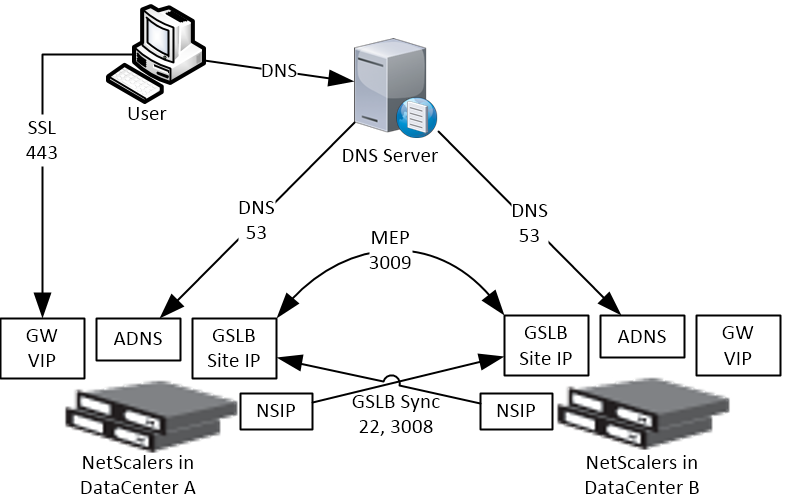
- Create ADNS listener on each ADC pair – DNS clients send DNS queries to the ADNS listeners. GSLB resolves a DNS query into an IP address, and returns the IP address in the DNS response.
- Create GSLB Sites (aka MEP Listener) – GSLB Sites usually correspond to different datacenters. GSLB Sites are also the IP address endpoints for Citrix ADC’s proprietary Metric Exchange Protocol (MEP), which is used by GSLB to transmit proximity, persistence, and monitoring information.
- Import Static Proximity Database – Citrix ADC includes a database that can be used to determine the geographical location of an IP address. Or you can subscribe to a geolocation service, and import its database.
- Delegate DNS sub-zone to ADC ADNS – in the original DNS zone, create a new sub-zone (e.g. gslb.company.com), and delegate the sub-zone to all ADNS listeners.
Repeatable GSLB Configuration for each DNS name:
- Create one or more GSLB Services per DNS name, and per IP address response – each GSLB Service corresponds to a single IP address that can be returned in response to a DNS Query.
- Optionally, bind a Monitor to each GSLB Service. Monitors determine if the GSLB Service is up or not.
- Create a GSLB Virtual Server per DNS name
- Bind a DNS name to the GSLB Virtual Server.
- For active/active – bind multiple GSLB Services to the GSLB Virtual Server, configure a load balancing method (e.g. proximity), and configure site persistence.
- For active/passive – bind the active GSLB Service. Create another GSLB Virtual Server with passive GSLB Service and configure as Backup Virtual Server.
- Alternatively, NetScaler ADC 13.1 and newer let you bind GSLB Services in priority order. See Citrix Docs for details.
- Create CNAME records for each delegated DNS name – in the main DNS zone, create a CNAME that maps the original DNS name to the delegated sub-zone. For example, CNAME citrix.company.com to citrix.gslb.company.com.
You will create separate GSLB Services, separate GSLB Virtual Servers, and separate CNAMEs for each DNS name. If you have a bunch of DNS names that you want to GSLB-enable, then you’ll repeat these steps for each GSLB-enabled DNS name.
Each datacenter has a separate ADNS listener IP address. DNS is delegated to all GSLB ADNS Listener IPs, and any one of them can respond to the DNS query. Thus, all ADC pairs participating in GSLB should have the same Per-DNS name configuration.
One ADC appliance for both public DNS/GSLB and internal DNS/GSLB?
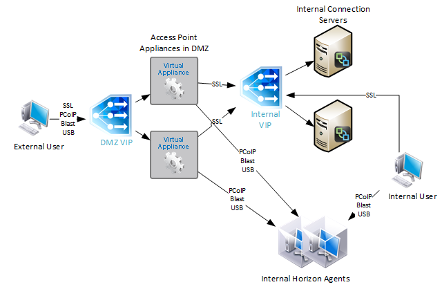
GSLB can be enabled both publically and internally. For public GSLB, configure it on DMZ ADC appliances, and expose the DNS listener to the Internet. For internal GSLB, configure it on separate internal ADC appliances/instances, and create an internal DNS listener.
Each ADC appliance only has one DNS table, so if you try to use the same ADC for both public DNS and internal DNS, then be aware that external users can query for internal GSLB-enabled DNS names.
One appliance resolving a single DNS name differently for internal and public
Let’s say you have a single DNS name citrix.company.com. When somebody external resolves the name, it should resolve to a public IP. When somebody internal resolves the name, it should resolve to an internal IP.
For internal GSLB and external GSLB of the same DNS name on the same ADC appliance, you can use DNS Policies and DNS Views to return different IP addresses depending on where users are connecting from. See Citrix CTX130163 How to Configure a GSLB Setup for Internal and External Users Using the Same Host Name.
If the Internet circuit in the remote datacenter goes down, then this should affect public DNS, since you don’t want to give out a public IP that isn’t reachable. But do you also want an Internet outage to affect internal DNS? Probably not. In that case, you would need different GSLB monitoring configurations for internal DNS and external DNS. However, if you have only a single GSLB Virtual Server with DNS Views, then you can’t configure different monitoring configurations for each DNS View.
To work around this limitation, create two separate GSLB Virtual Servers with different monitoring configurations. Internal DNS uses a CNAME record to reach the GSLB Virtual Server configured for internal monitoring:
- External citrix.company.com:
- Configure ADC GSLB for citrix.company.com.
- On public DNS, delegate citrix.company.com to the ADC DMZ ADNS services.
- Internal citrix.company.com:
- Configure ADC GSLB for citrixinternal.company.com or something like that.
- On internal DNS, create CNAME for citrix.company.com to citrixinternal.company.com
- On internal DNS, delegate citrixinternal.company.com to ADC internal ADNS services.
Remote Internet Monitoring
For public DNS/GSLB, you don’t want to give out a remote public IP address if that remote public IP address is not reachable. That means the local ADC will need to somehow determine if the remote datacenter has Internet connectivity or not. Here are some methods of verifying the remote Internet connection:
- Route GSLB Metric Exchange Protocol (MEP) across the Internet. If MEP goes down, then all IP addresses associated with the remote GSLB Site are assumed to be down, and thus the local ADC will stop giving out those remote IP addresses.
- Bind explicit monitors to each GSLB Service, and ensure the monitoring is routed across the Internet.
GSLB IP Addresses
GSLB is separate from data traffic. The GSLB IP addresses are separate from the IP addresses needed for data.
Some GSLB-specific IP Addresses are needed on each ADC pair:
- ADNS Listener IP: An ADC IP that listens for DNS queries.
- The ADNS listener IP is typically an existing SNIP on the appliance.
- For external DNS, create a public IP for the ADNS Listener IP, and open UDP 53 and TCP 53, so Internet-based DNS servers can access it.
- A single ADC appliance can have multiple ADNS listeners – typically one ADNS listener for public, and another ADNS listener for internal.
- GSLB Site IP / MEP listener IP: An ADC IP that will be used for ADC-to-ADC GSLB communication. This communication is called MEP or Metric Exchange Protocol. MEP transmits the following between GSLB-enabled ADC pairs: load balancing metrics, proximity, persistence, and monitoring.
- GSLB Sites – On ADC, you create GSLB Sites. GSLB Sites are the endpoints for the MEP communication. Each ADC pair is configured with the MEP endpoints for the local appliance pair, and all remote appliance pairs.
- TCP Ports – MEP uses port TCP 3009 or TCP 3011 between the ADC pairs. TCP 3009 is encrypted.
- The ADNS IP address can be used as the MEP endpoint IP.
- MEP endpoint can be any IP – The MEP endpoint IP address can be any IP address and does not need to be a SNIP or ADNS.
- One MEP IP per appliance – there can only be one MEP endpoint IP address on each ADC pair.
- Route MEP across Internet? – If you route MEP across the Internet, and if the MEP connection is interrupted, then Internet at one of the locations is probably not working. This is an easy way to determine if remote Internet is up or not. If you don’t route MEP across the Internet, then you’ll need to configure every remote-site GSLB Service with a monitor to ensure that the remote Internet is up.
- Public IPs for MEP Enpoints – if you route MEP across the Internet, then you’ll need public IPs for each publically-accessible MEP endpoint IP address.
- Public Port for MEP: Open port TCP 3009 between the MEP Public IPs. Make sure only the MEP IPs can access this port on the other ADC . Do not allow any other device on the Internet to access this port. Port 3009 is encrypted.
- GSLB Sync Ports: To use GSLB Configuration Sync, open ports TCP 22 and TCP 3008 (secure) from the NSIP (management IP) to the remote public MEP IP. The GSLB Sync command runs a script in BSD shell and thus NSIP is always the Source IP.
- Public IP Summary: In summary, for public GSLB, if MEP and ADNS are listening on the same IP, then you need one new public IP that is NAT’d to the DMZ IP that is used for ADNS and MEP (GSLB Site IP).
- Each datacenter has a separate public IP.
- DNS is delegated to all public ADNS IP listeners.
GSLB Wizard
NetScaler 12 and Citrix ADC 12.1 and newer have a GSLB Wizard at Traffic Management > GSLB.
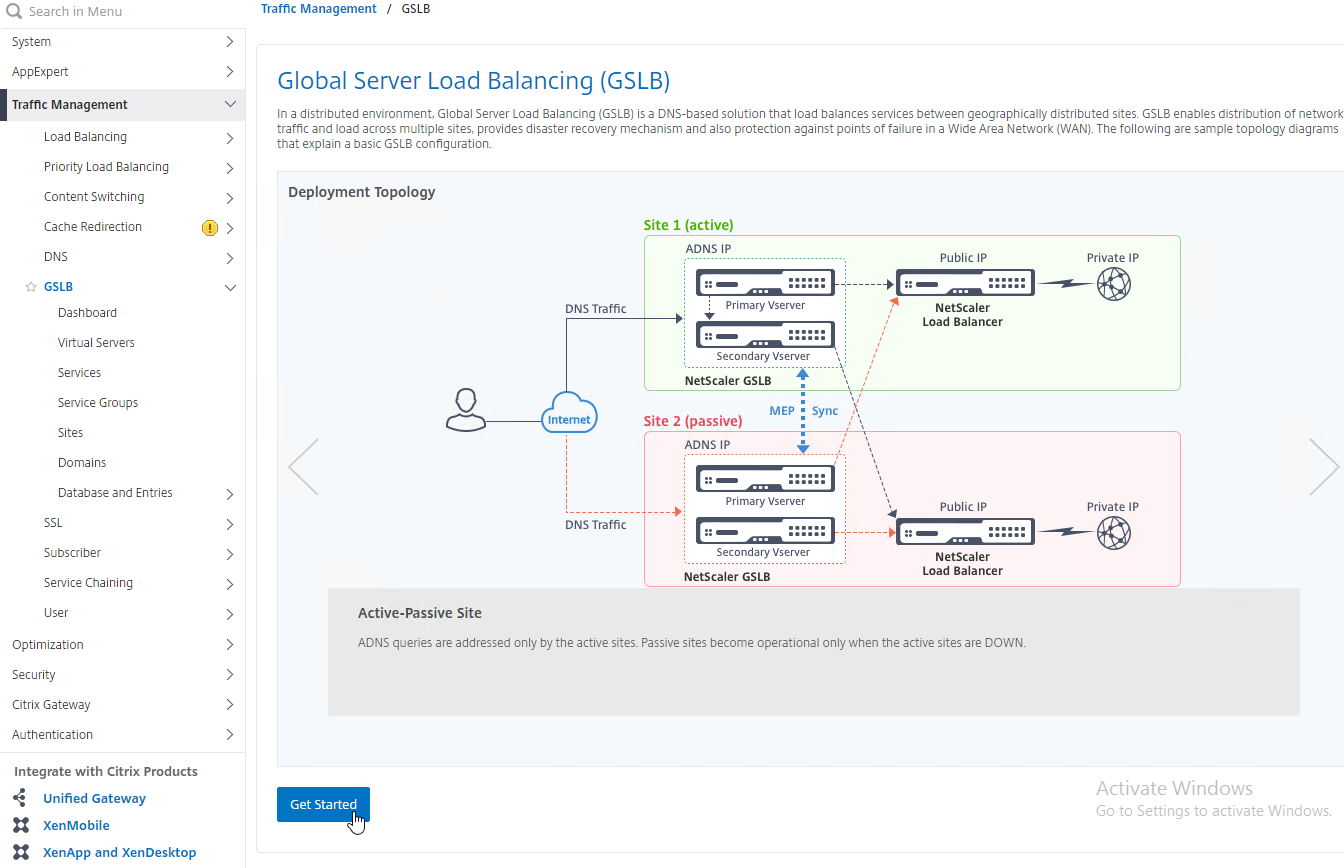
However, the wizard doesn’t really save any time or steps, so it won’t be documented here.
ADNS Listener
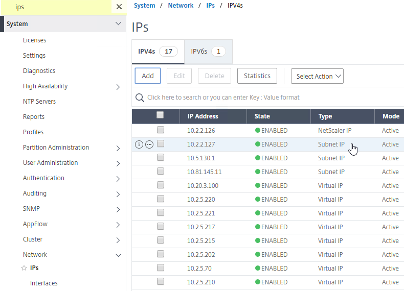
- At System > Network > IPs, identify a Citrix ADC-owned IP that you will use as the ADNS listener. This is typically a SNIP.
- Create a public IP for the ADNS Service IP and configure firewall rules. UDP 53 and TCP 53 need to be opened from the Internet to the public IP that NATs to the ADNS Listener IP address.
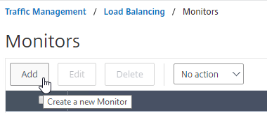
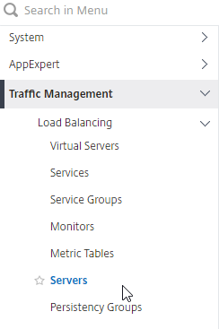
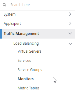
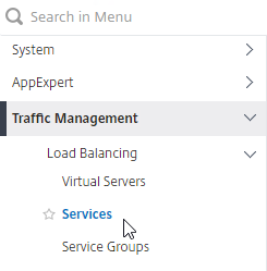
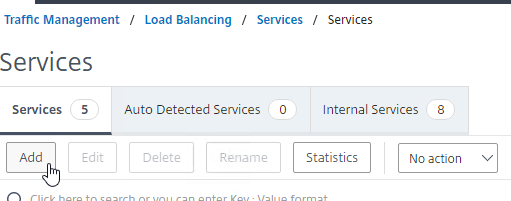
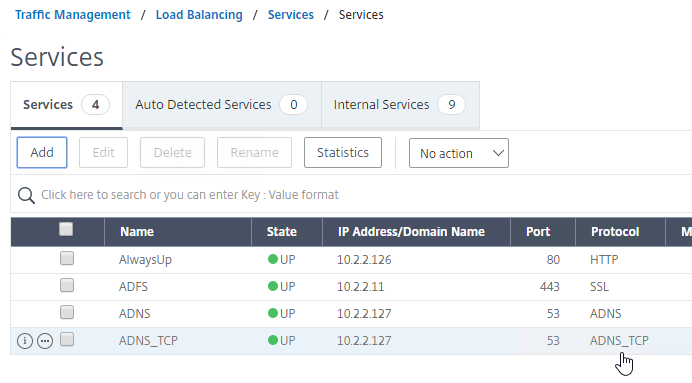
- On the left, expand Traffic Management > Load Balancing, and click Services.
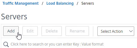
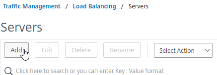
- On the right, click Add.
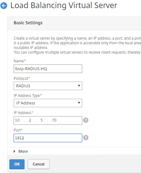
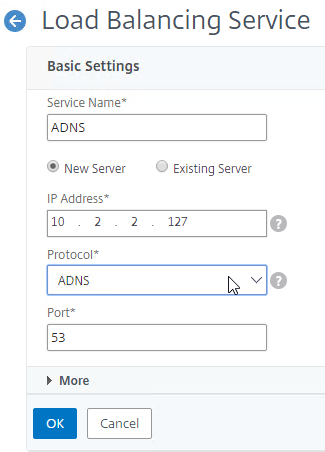
- In the Basic Settings section, do the following:
- Name the service ADNS or similar.
- In the IP Address field, enter an appliance SNIP.
- In the Protocol drop-down, select ADNS.
- Click OK.
- No other configuration is needed so scroll down and click Done to close the Load Balancing Service properties.

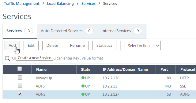
- Highlight the ADNS service you just added and then click Add to create another Service while copying some of the settings from the previously created Service.
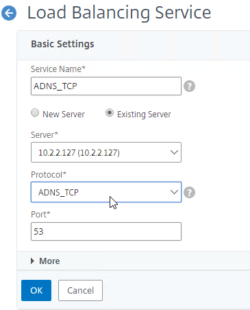
- Change the Service Name to ADNS_TCP or similar.
- Change the Protocol drop-down to ADNS_TCP.
- Click OK to close the Basic Settings section.
- No other configuration is needed so scroll down and click Done to close the Load Balancing Service properties.
- You should have two ADNS services on the same IP address: one for ADNS, and one for ADNS_TCP.
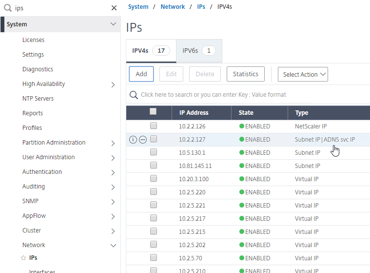
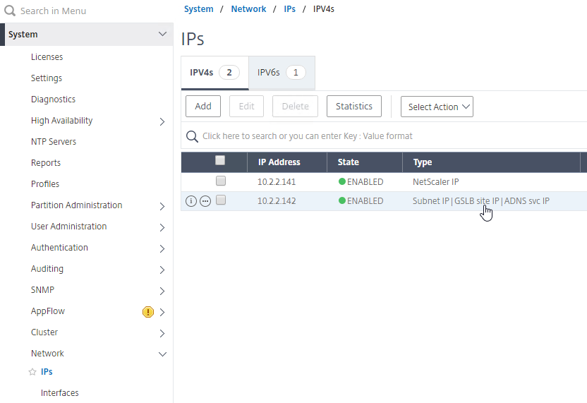
- On the left of the console in the menu, expand System, expand Network, and then click IPs.
- On the right, you’ll see the SNIP is now marked as the ADNS svc IP.
- Repeat the ADNS configuration on the other appliance pair in the other datacenter. Except the other appliance will use its own SNIP as the ADNS Service listener IP address.
- Your ADC appliances are now DNS servers.
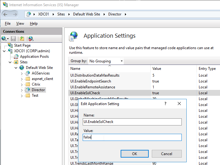
DNS Security
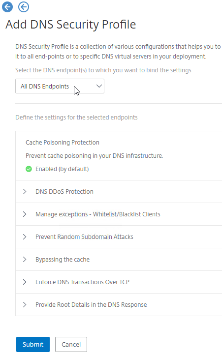
- Citrix ADC includes DNS Security Options, at Security > DNS Security, which can protect your ADNS service.
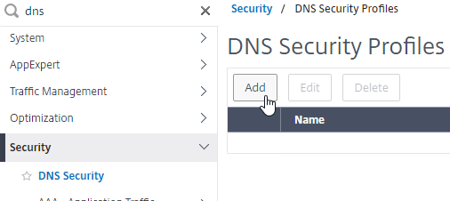
- To protect ADNS, set the Profile to All DNS Endpoints.
Metric Exchange Protocol
This section details MEP configuration between two GSLB Sites. See Citrix Docs for larger Parent-Child Topology Deployment Using the MEP Protocol.
GSLB Sites
- The local GSLB Site IP can be any IP, including the same SNIP that you used for ADNS.
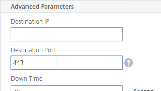
- Open the firewall rules for Metric Exchange Protocol. The GSLB Site IP on this appliance pair uses TCP 3009 to communicate with the GSLB Site IP on the other appliance pair.
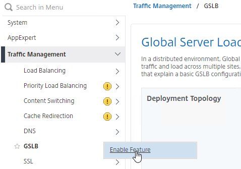
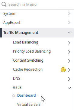
- On the left, expand Traffic Management, right-click GSLB, and enable the feature.
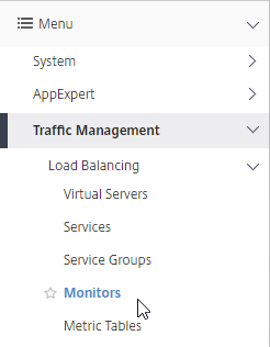
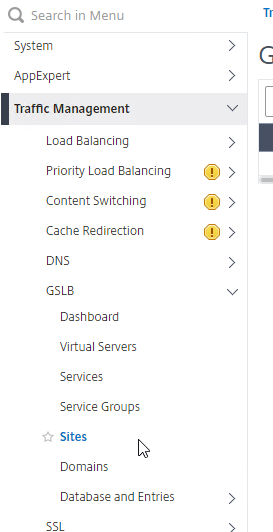
- Expand GSLB, and click Sites.
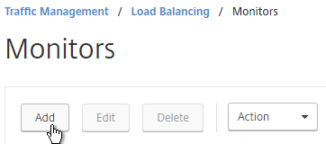
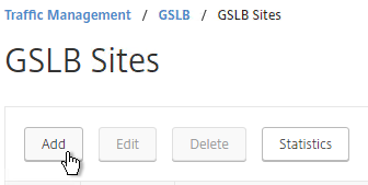
- On the right, click Add.
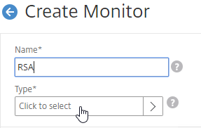
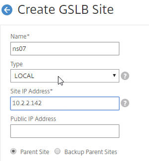
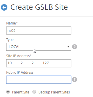
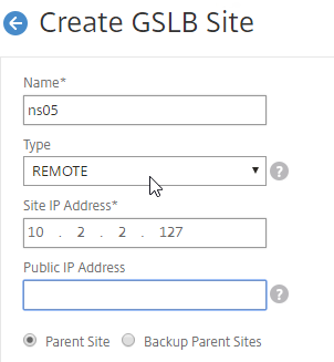
- In the Create GSLB Site page, do the following:
- We’re adding the local site first. Enter a descriptive name for the local site.
- In the Site Type drop-down, select LOCAL.
- In the Site IP Address field, enter an IP that this appliance will listen for MEP traffic. This is typically a SNIP and can the same as your ADNS IP.
- For Internet-routed GSLB MEP, in the Public IP Address field, enter the public IP that is NAT’d to the GSLB Site IP.
- For internal GSLB MEP, there is no need to enter anything in the Public IP field.
- Scroll down, and click Create, to close the Create GSLB Site page.

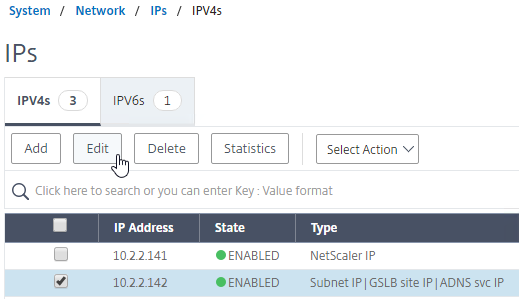
- Go back to System > Network > IPs, and notice that the IP is now marked as a GSLB site IP.
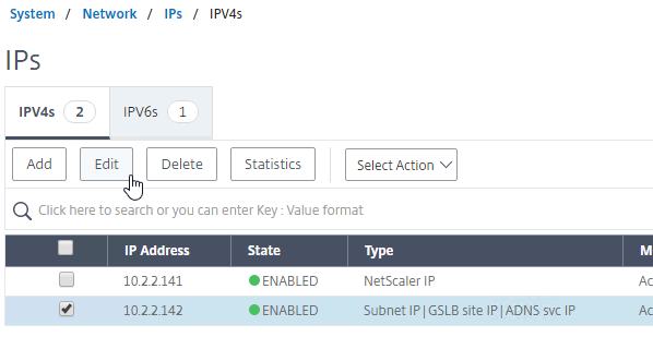
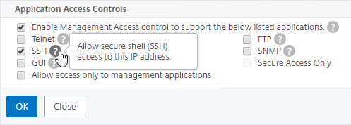
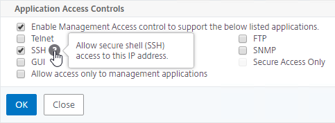
- If you want to use the GSLB Sync Config feature, then you’ll need to edit the GSLB site IP, and enable Management Access.
- Scroll down, and enable Management Access. SSH is all you need.
- Go to the other appliance pair, and also create the Local GSLB site using its GSLB site IP, and its public IP that is NAT’d to the GSLB site IP.
- In System > Network > IPs on the remote appliance, there should now be a GSLB site IP. If GSLB Sync is desired, enable management access on that IP and ensure SSH is enabled.
- Now on each appliance, add another GSLB Site, which will be the Remote GSLB site.
- In the Create GSLB Site page, do the following:
- Enter a descriptive name for the remote site.
- Select REMOTE as the Type.
- Enter the other appliance’s actual GSLB Site IP as configured on the appliance. This IP does not need to be reachable.
- In the Public IP Address field, enter the public IP that is NAT’d to the GSLB Site IP on the other appliance. For MEP, TCP 3009 must be open from the local GSLB Site IP, to the remote public Site IP. For GSLB sync, TCP 22, and TCP 3008, must be open from the local NSIP, to the remote public Site IP.
- Click Create.
- Repeat on the other appliance.
RPC
MEP defaults to unencrypted on TCP 3011. To fix that:
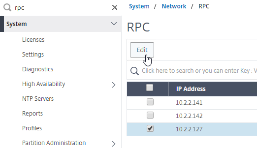
- On the left, expand System, expand Network, and click RPC.
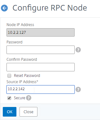
- On the right, right-click the new RPC address (the other site’s GSLB Site IP), and click Edit.
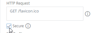
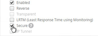
- On the bottom, check the box next to Secure. In ADC 13.0 64.x and 12.1 build 61.x onwards, Secure is enabled by default. (source = Citrix CTX292743 Configuration Sync, Propagation and MEP Propagation Might Fail After Upgrade to 13.0 64.x\12.1 61.x)
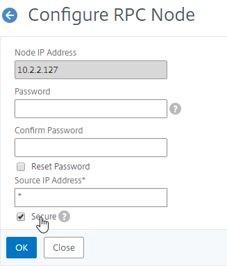
- If your local GSLB Site IP is not a SNIP, then you’ll need to change the RPC Node to use the local GSLB Site IP as the source IP. In the Source IP Address field, enter the local GSLB Site IP.
- Click OK when done.
- Do the same thing on the other appliance.
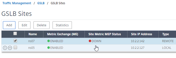
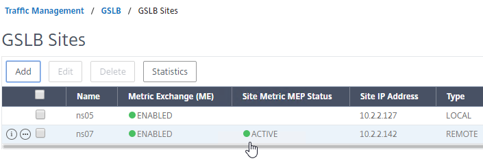
- If you go back to GSLB > Sites, you should see it as active.
See Citrix Tech Zone Troubleshooting Citrix GSLB MEP Cheat Sheet
If your MEP connection between GSLB Sites flaps, it might be useful to introduce a delay before remote GSLB Services are marked as Down.
- You can do this at Traffic Management > GSLB > Dashboard.
- On the right, click Change GSLB settings.
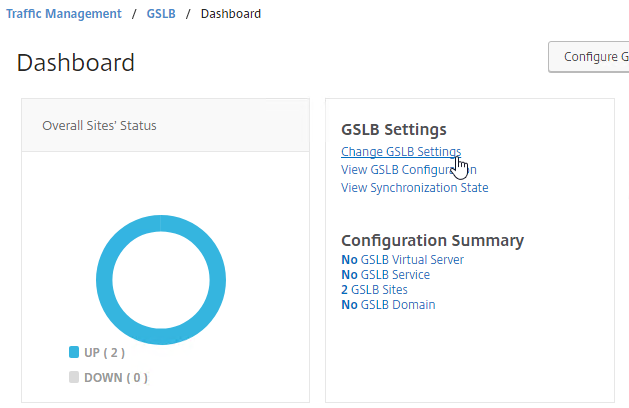
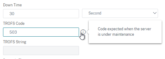
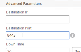
- In the GSLB Service State Delay Time (secs) field, enter a delay before the GSLB Services are marked as down when MEP goes down.
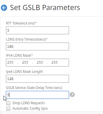
set gslb parameter -GSLBSvcStateDelayTime 15
Static Proximity Geo Location Database
If you want to use DNS Policies, or Static Proximity GSLB Load Balancing, or Responders based on user’s location, import a geo location database.
Citrix ADC has a built-in database at /var/netscaler/inbuilt_db/ that you can use. Or you can download a database. Common free databases are:
For IP2Location, see the blog post Add IP2Location Database as NetScaler’s Location File for instructions on how to import.
CTX235799 NetScaler data formats for Location Database Import
Citrix Github has a Citrix-ADC-GSLB-GeoIP-Conversion-Tool that can convert Maxmind GeoIP City database to Citrix ADC (NetScaler) format.
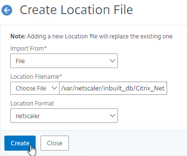
Import the Built-in Geo database:
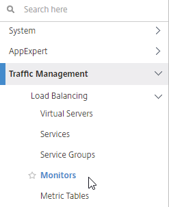
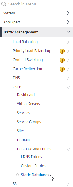
- In the Citrix ADC GUI, on the left, expand Traffic Management, expand GSLB, expand Database and Entries, and click Static Databases.
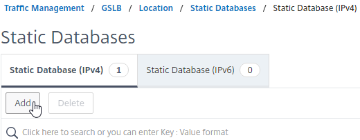
- On the right, click Add.
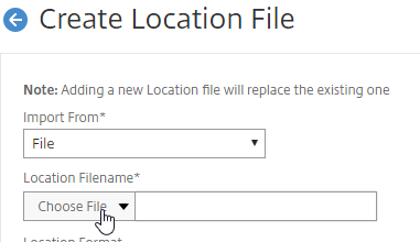
- Change the Import From selection to File.
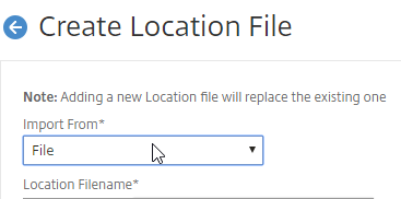
- Click Choose File.
- Browse to /var/netscaler/inbuilt_db/. To browse to the directory, select var, and then click Open.
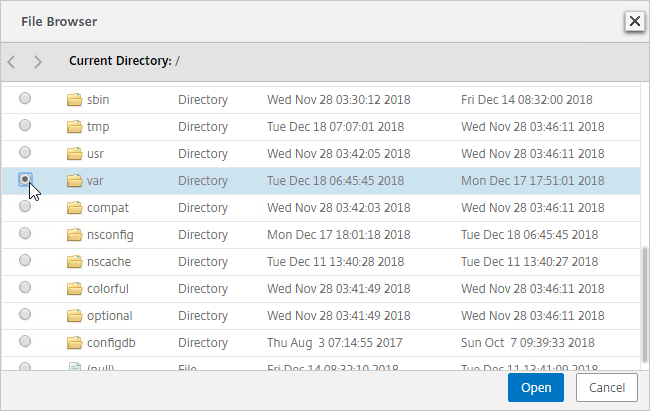
- Repeat for each directory until you reach /var/netscaler/inbuilt_db.
- In ADC 12.1, you can select the file named Citrix_Netscaler_InBuild_GeoIP_DB_IPv4. In NetScaler 12.0, select the only file shown. Then click Open.
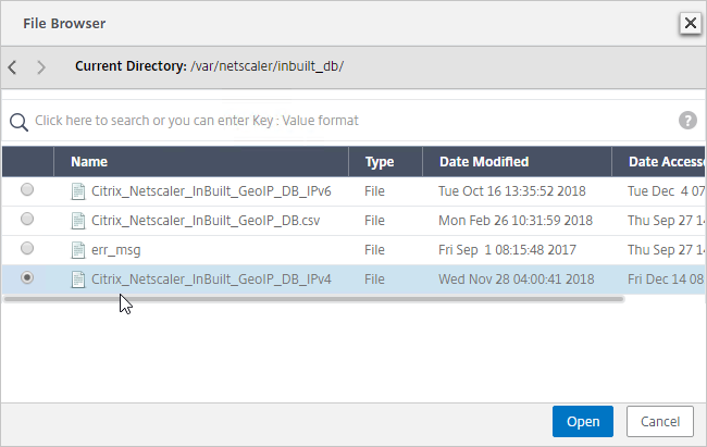
- In the Location Format field, if using the built-in database, select netscaler, and click Create.
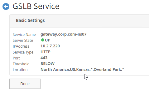
- After you later create a GSLB Service, when you open the GSLB Service, the public IP will be translated to a location based on the contents of the static proximity database.
Private IP Blocks
Geo Location databases only contain entries for Public IPs. For Private IPs, do the following:
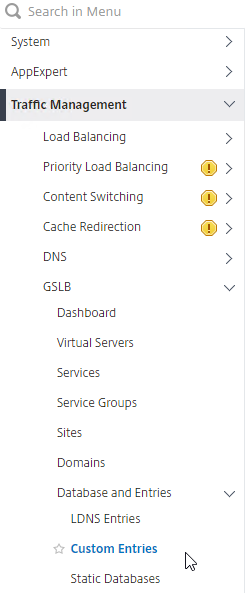
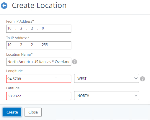
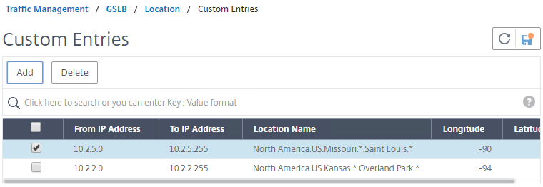
- On the left, expand Traffic Management, expand GSLB, expand Database and Entries, and click Custom Entries.
- On the right, click Add.
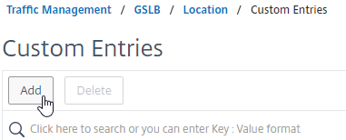
- Enter a range of IP addresses for a particular location.
- Enter a Location Name in Geo Location format, which is typically six location words separated by periods. You can look in the static proximity database for examples.
- Make sure you enter coordinates. Google can find you coordinates for cities.
- Click Create.
- Continue creating Custom Entries for other private IP blocks.
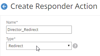
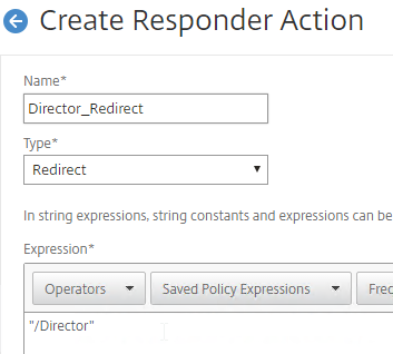
Use Geo Locations
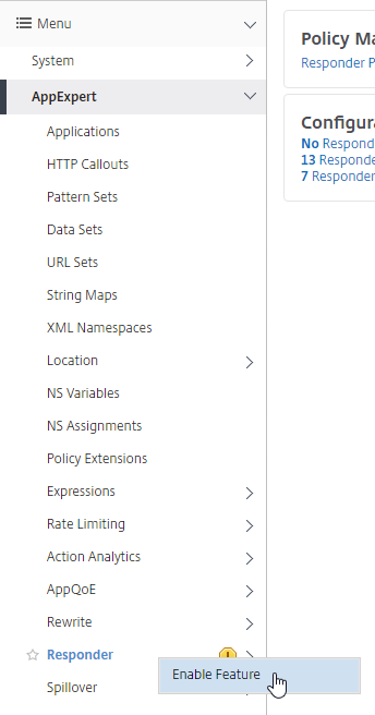
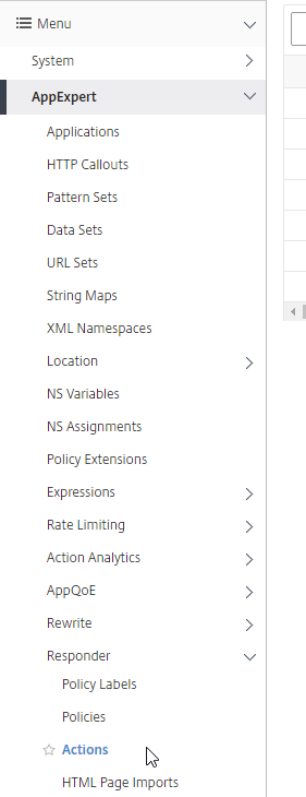
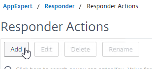
You can use the Geo locations in a DNS Policy, static proximity GSLB Load Balancing, Responders, and Rewrites:
Prior to Citrix ADC 12.1 build 50, the only option in policy expressions is to match a known location.
Citrix ADC 12.1 build 50 and newer lets you extract the user’s location and use it in policy expressions.
GSLB Services
GSLB Services represent the IP addresses that are returned in DNS Responses. The IP addresses represented by GSLB Services do not need to be hosted on a Citrix ADC, but Citrix ADC-owned IP addresses (e.g. load balancing VIPs) have additional GSLB Site Persistence options (e.g. cookie-based persistence).
- Each potential IP address in a DNS response is a separate GSLB Service.
- GSLB Services are associated with GSLB Sites.
- GSLB Service configuration is identical for active/active and active/passive. GSLB Virtual Server configuration defines active/active or active/passive, not GSLB Services.
GSLB should be configured identically on all Citrix ADC pairs that are responding to DNS queries. Since you have no control over which Citrix ADC will receive the DNS query, you must ensure that both Citrix ADC pairs are giving out the same DNS responses.
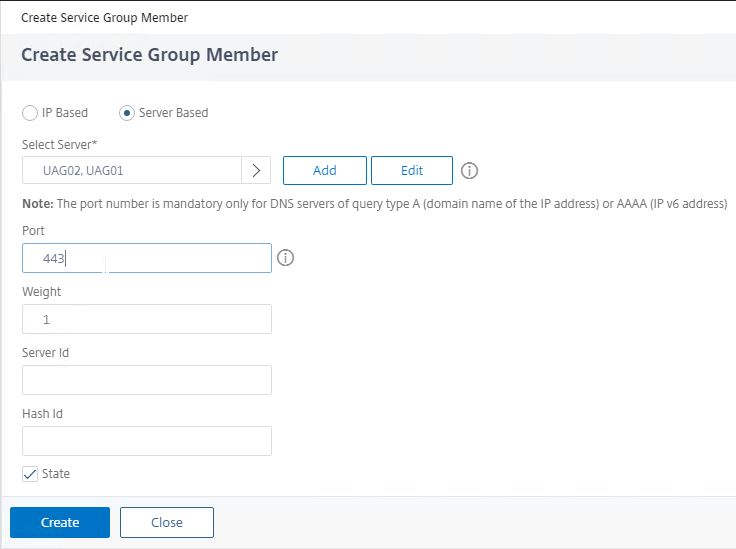
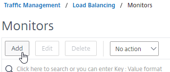
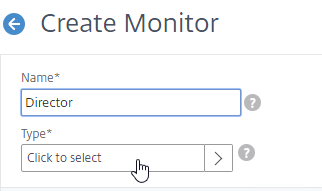
To create a GSLB Service:
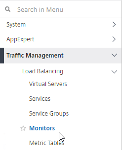
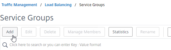
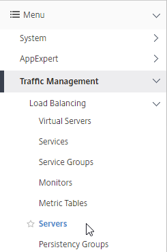
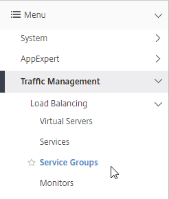
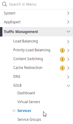
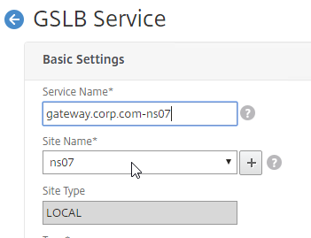
- On the left, expand Traffic Management > GSLB, and click Services.
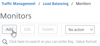
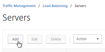
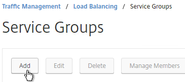
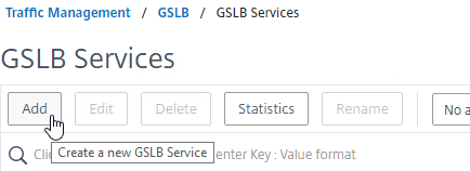
- On the right, click Add.
- The service name should be similar to the DNS name that you are trying to GSLB. Include the site name in the service name.
- Select one of the GSLB Sites. The IP address you’re configuring in this GSLB Service should be geographically located in the selected GSLB Site.
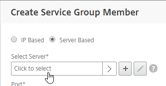
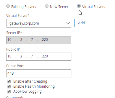
- On the bottom part, if the IP address is owned by this Citrix ADC, then select Virtual Servers, and select a Virtual Server that is already defined on this appliance. It should automatically fill in the other fields. This option is only available when creating a GSLB Service in the Local GSLB Site.
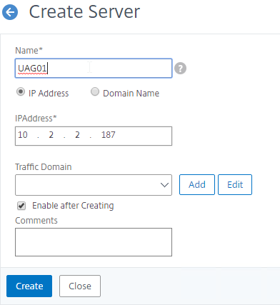
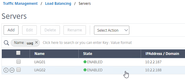
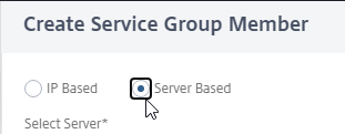
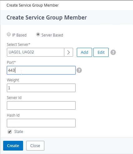
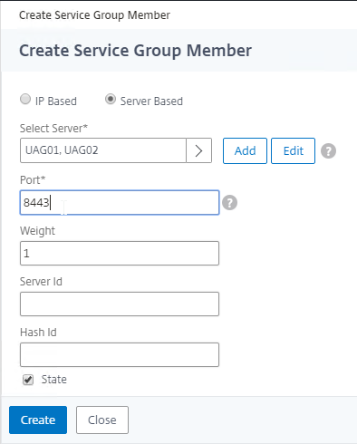
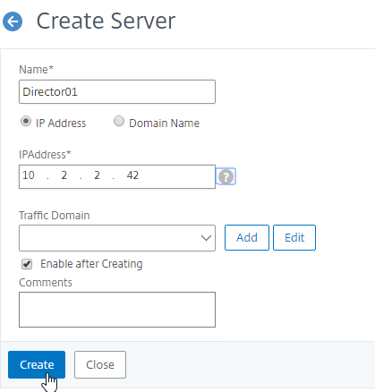
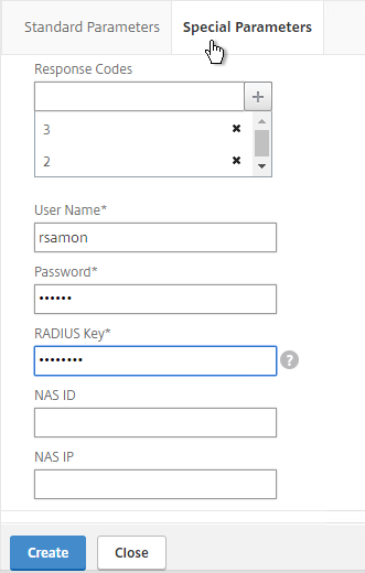
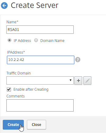
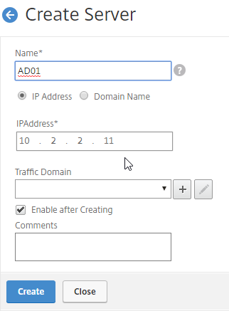
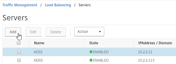
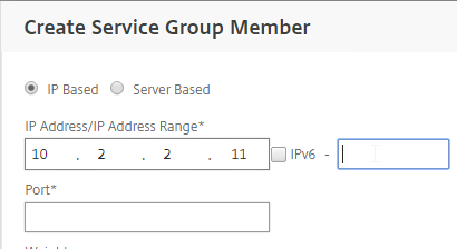
- If the IP address is not owned by this Citrix ADC, then change the selection to New Server, and enter the remote IP address in the Server IP field.
- The Server IP field is the IP address that Citrix ADC will monitor for reachability.
- If the remote IP is owned by a different Citrix ADC that is reachable by MEP, then enter the actual VIP configured on that remote Citrix ADC. The Server IP does not need to match what is returned to the DNS Query.
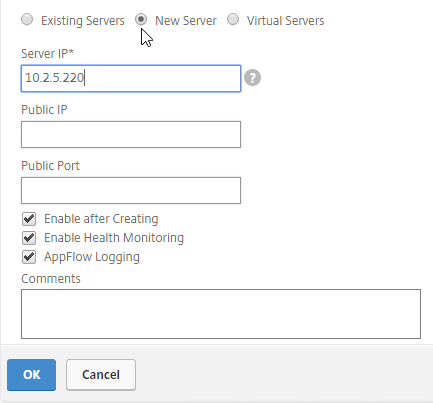
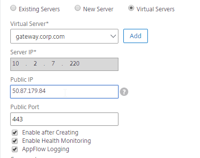
- In the Public IP field, enter the IP address that will be returned to the DNS Query. If you leave Public IP blank, then Citrix ADC will copy the Server IP to the Public IP field. For Public GSLB, the Public IP field is usually a Public IP address. For internal GSLB, the Public IP field is usually an internal IP, and probably matches the Server IP.
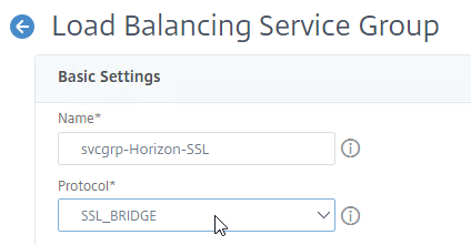
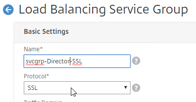
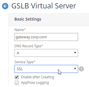
- Scroll up, and make sure the Service Type is SSL. It’s annoying that Citrix ADC doesn’t set this drop-down correctly.
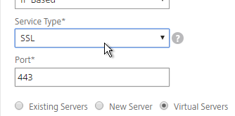
- Scroll down, and click OK, to close the Basic Settings section.

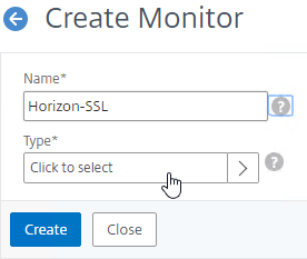
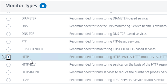
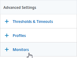
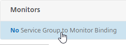
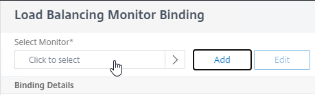
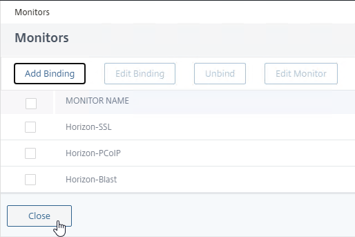
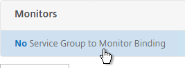
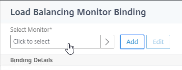
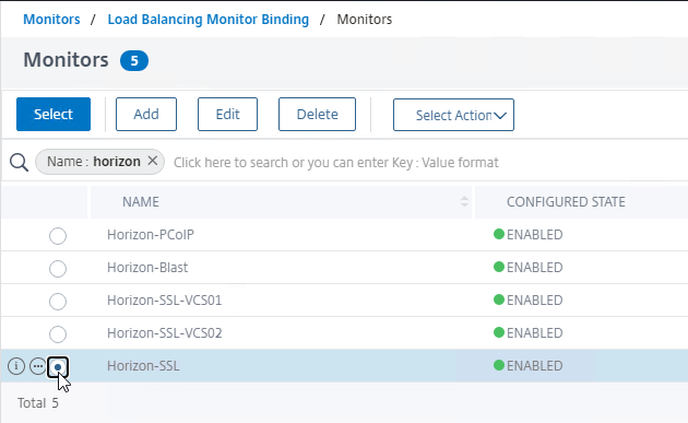
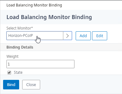
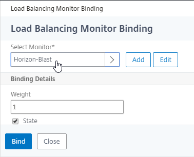
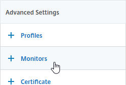
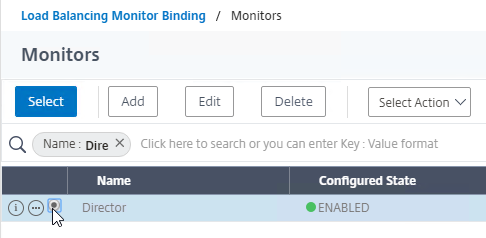
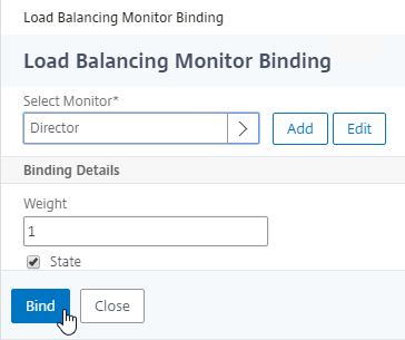
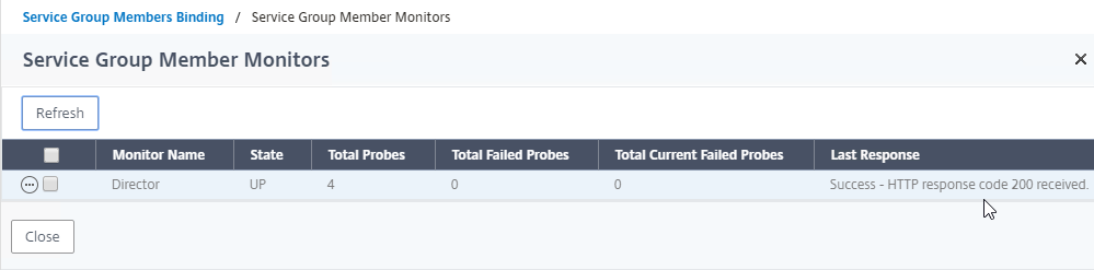
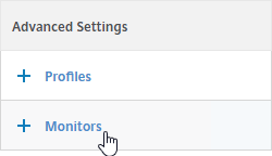
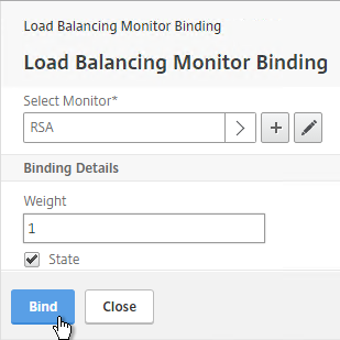
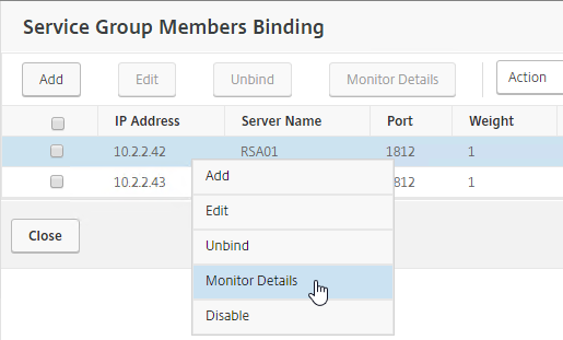
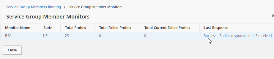
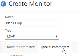
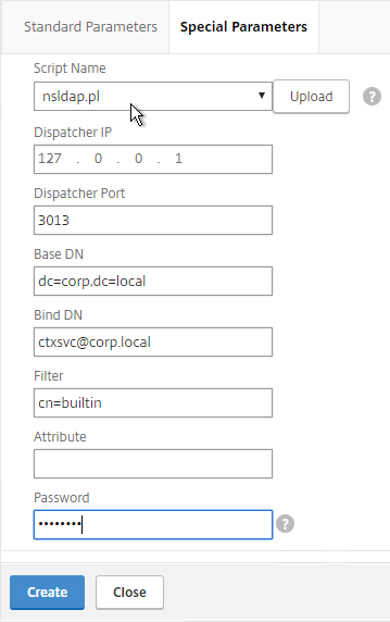
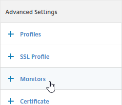
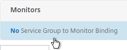
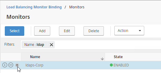
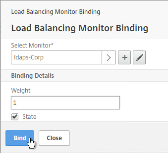
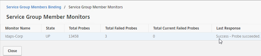
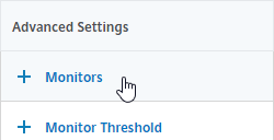
- GSLB Service Monitoring – on the right, in the Advanced Settings column, you can click Monitors to bind a monitor to this GSLB Service. Review the following notes before you bind a monitor.
- Local Citrix ADC VIP – If the GSLB Service IP is a VIP on the local appliance, then GSLB will simply use the state of the local traffic Virtual Server (Load Balancing, Content Switching, or Gateway). There’s no need to bind a monitor to the GSLB Service.
- Remote Citrix ADC VIP – If the GSLB Service IP is a VIP on a remote appliance, then GSLB will use MEP to ask the other appliance for the state of the remote traffic Virtual Server. In both cases. There’s no need to bind a monitor to the GSLB Service.
- GSLB Monitor overrides other Monitoring methods – If you bind a monitor to the GSLB Service, then MEP and local Virtual Server state are ignored (overridden).
- Here are some reasons for binding a monitor to the GSLB Service:
- IP is not on a Citrix ADC– If the GSLB Service IP is not hosted on a Citrix ADC, then only a monitor can determine if the Service IP is up or not.
- Monitor remote Internet – For Public DNS, if MEP is not routed through the Internet, then you need some method of determining if the remote Internet circuit is up or not. In that case, you’ll need to bind monitors directly to the GSLB Service. The route of the Monitor should go across the Internet. Or you can ping the Internet router in the remote datacenter to make sure it’s reachable.
- Traffic Domains – If the GSLB Service IP is in a non-default Traffic Domain, then you will need to attach a monitor, since GSLB cannot determine the state of Virtual Servers in non-default Traffic Domains.
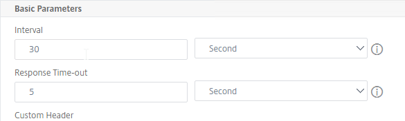
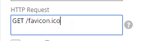
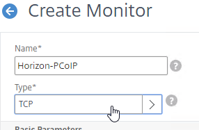
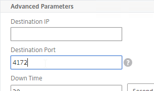
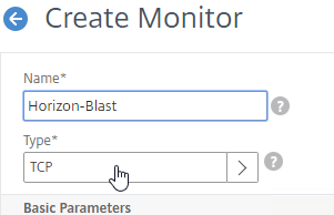
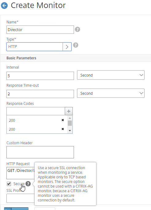
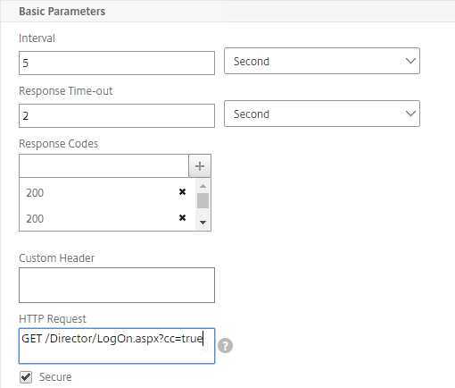
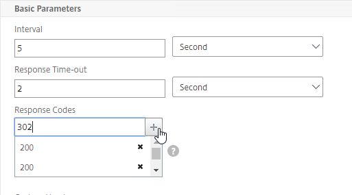
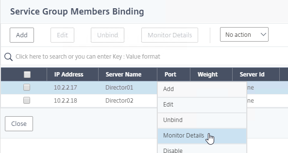
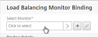
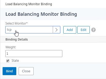
- TCP monitor – for TCP services (not UDP), a simple TCP monitor is probably all you need. The TCP monitor tries to connect to the GSLB Service Public IP address using the SNIP of the local appliance. Make sure firewall on both sides allows this connection.
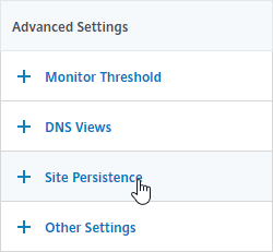
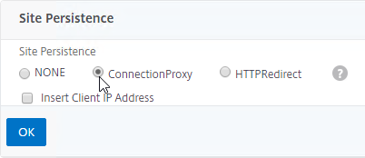
- Active/Active Site Persistence – If you intend to do GSLB active/active, and if you need site persistence, then on the right you can add Site Persistence and enable Connection Proxy or HTTP Redirect. See Citrix Blog Post Troubleshooting GSLB Persistence with Fiddler for more details. This only works with GSLB Service IPs that match Virtual Server VIPs on Citrix ADC appliances reachable through MEP.
- Scroll down, and click Done, to finish creating the GSLB Service.

- Create additional GSLB Services for each IP address that will be returned to a DNS query. There should be at least two for each DNS name.
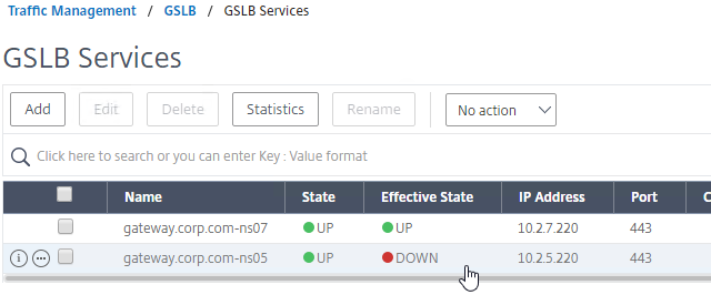
- When creating a GSLB Service, select the correct Site, and make sure Service Type = SSL.
- The State will probably be down until the other ADC is configured.
Manually Synchronize GSLB Configuration
Copy the GSLB Service Configuration to the remote Citrix ADC pair. You can either repeat the GUI steps listed above. Or you can do the following:
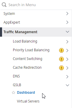
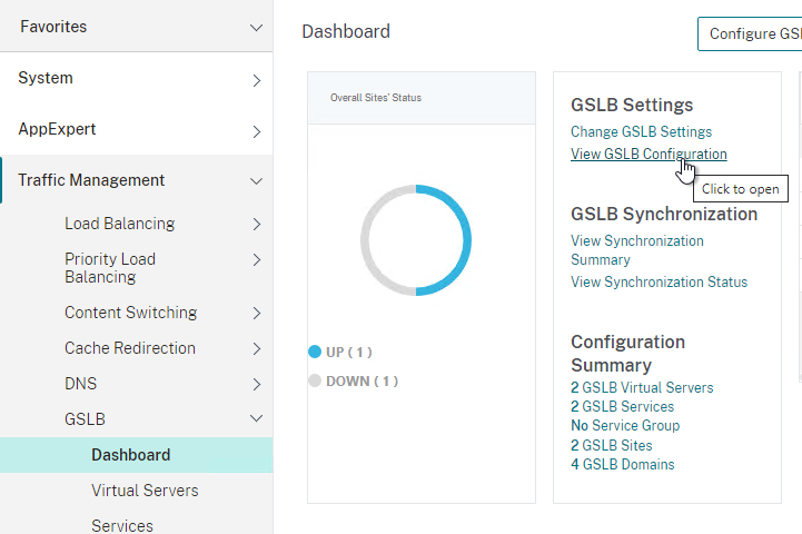
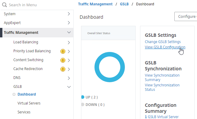
- On the left, expand Traffic Management, expand GSLB, and click Dashboard.
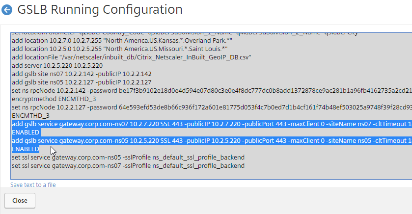
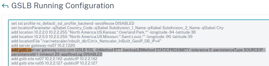
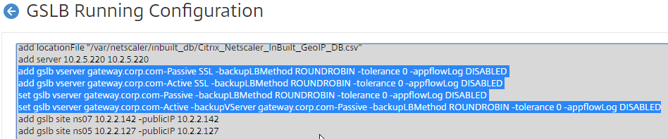
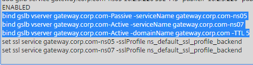
- On the right, click View GSLB Configuration.
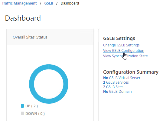
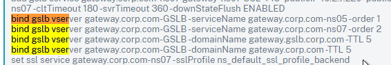
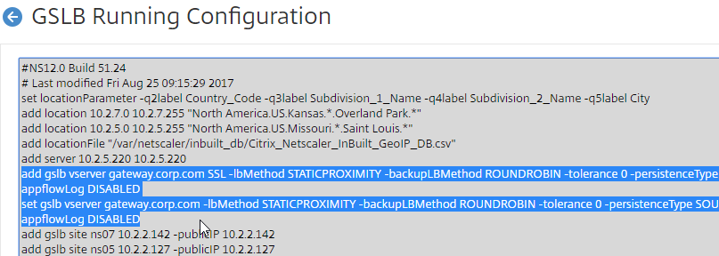
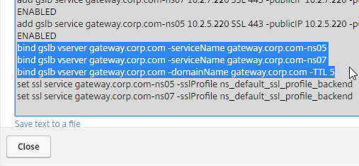
- This shows you all of the CLI commands for GSLB. Look for add gslb service commands. You can copy them, and run them (SSH) on other Citrix ADC pairs that are participating in GSLB.
GSLB Virtual Server
GSLB Virtual Server is the entity that links a DNS name with GSLB Services.
For Active/Passive GSLB in NetScaler ADC 13.1 or newer, GSLB Services can be bound in priority order. GSLB will give out the IP address of the lowest order GSLB Service. If that GSLB Service is down, then GSLB will give out the IP address of the next order GSLB Service.
- Create a GSLB Virtual Server.
- Bind the active GSLB Service but set the Order to 1.
- Bind the passive GSLB Service but set the Order to 2.
- Bind a DNS name to the GSLB Virtual Server.
- Repeat the GSLB Virtual Server configuration on other Citrix ADC pairs participating in GSLB.
- Delegate the DNS name to Citrix ADC ADNS.
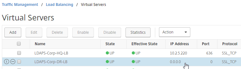
For Active/Passive GSLB, the Active GSLB Virtual Server will give out a single IP address if that IP address up. If the GSLB Service is down, then it will fail over to a Backup GSLB Virtual Server that gives out a different IP address.
- Create a GSLB Virtual Server for the Passive IP address.
- Bind the Passive GSLB Service to the Passive GSLB Virtual Server.
- Create another GSLB Virtual Server for the Active IP address.
- Bind the Active GSLB Service to the Active GSLB Virtual Server.
- Configure Backup Virtual Server pointing to the Passive GSLB Virtual Server.
- Bind a DNS name to the Active GSLB Virtual Server.
- Repeat the GSLB Virtual Server configuration on other Citrix ADC pairs participating in GSLB.
- Delegate the DNS name to Citrix ADC ADNS.
For Active/Active GSLB, a single GSLB Virtual Server gives out multiple IP addresses based on load balancing method and site persistence.
- Create one GSLB Virtual Server.
- Bind two or more GSLB Services to the Virtual Server.
- Configure the GSLB Virtual Server Load Balancing Method – e.g., Proximity
- Configure Site Persistence:
- Source IP persistence is configured on the GSLB Virtual Server.
- Cookie Persistence is configured on the GSLB Services.
- Bind a DNS name to the GSLB Virtual Server.
- Repeat the GSLB Virtual Server configuration on other Citrix ADC pairs participating in GSLB.
- Delegate the DNS name to Citrix ADC ADNS.
Configure Active/Passive GSLB in NetScaler ADC 13.1 and newer
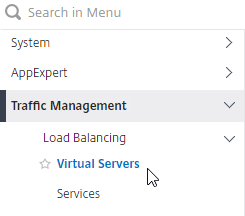
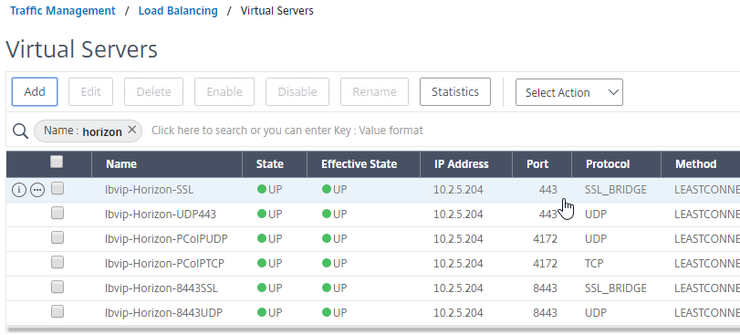
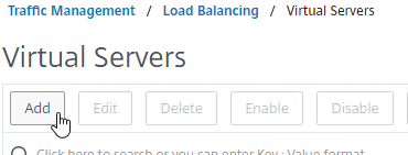
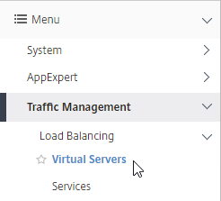
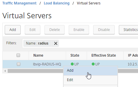
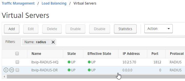
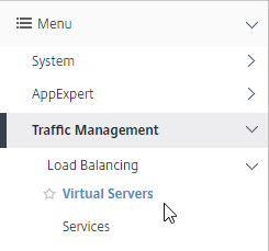
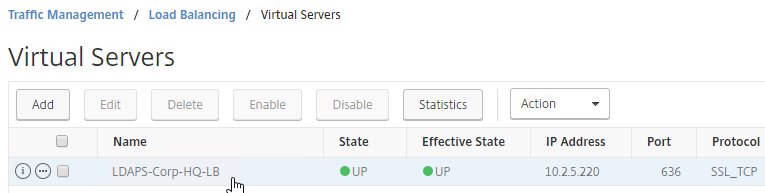
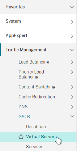
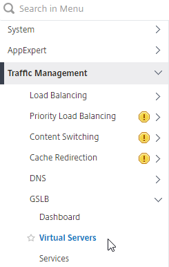
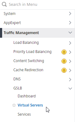
- On the left, expand Traffic Management, expand GSLB, and click Virtual Servers.
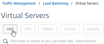
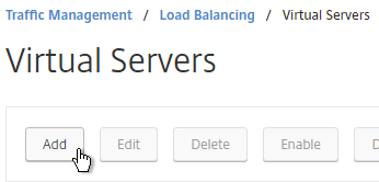
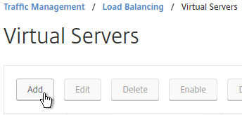
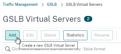
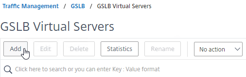
- On the right, click Add.
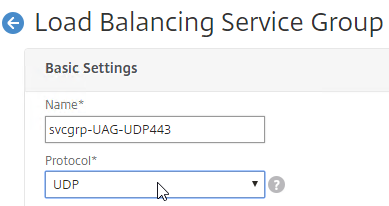
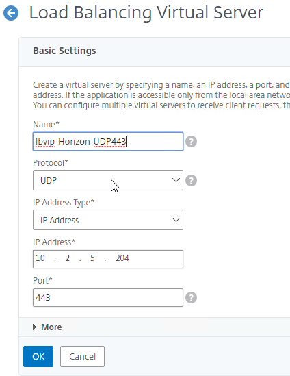
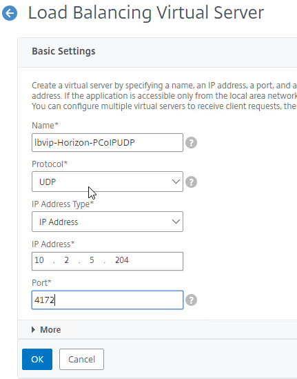
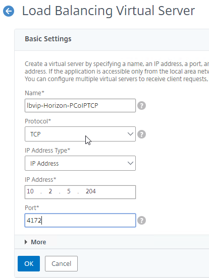
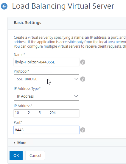
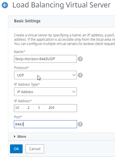
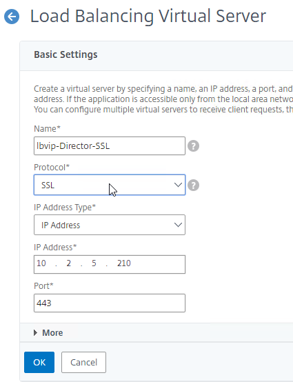
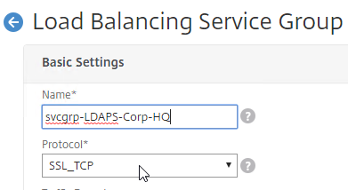
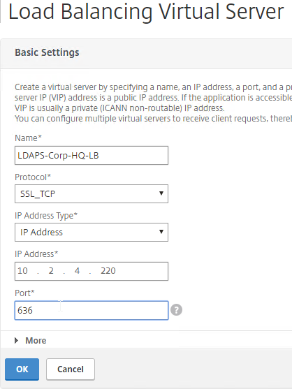
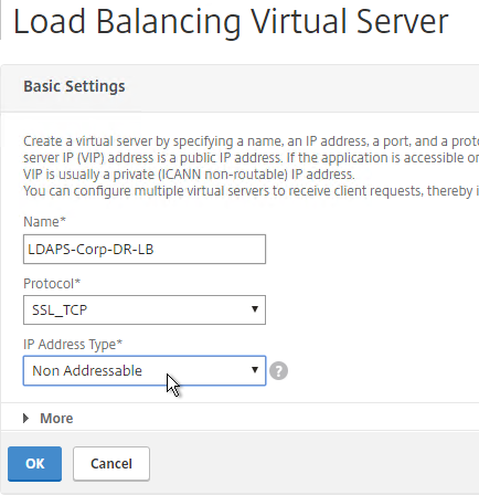
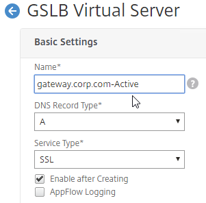
- In the Basic Settings section, do the following:
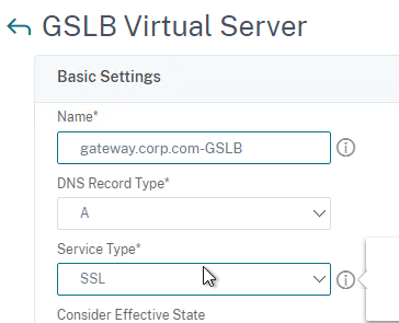
- Give the GSLB Virtual Server a descriptive name.
- Set the Service Type to SSL to match the GSLB Sevices you intend to bind.
add gslb vserver <gslb_vserver_name> SSL
- Click OK to close the Basic Settings section.

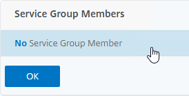
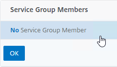
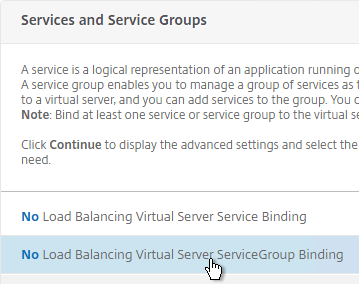
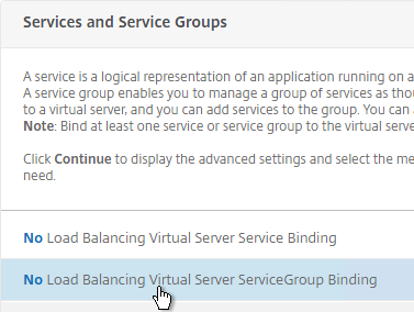
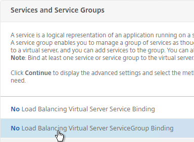
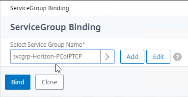
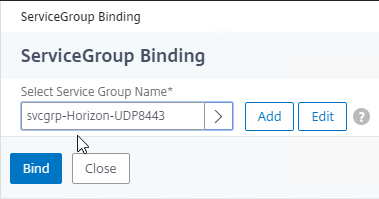
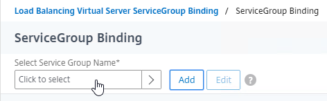
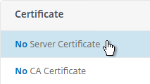
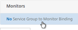
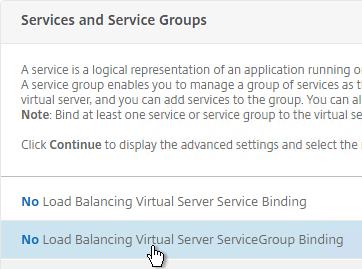
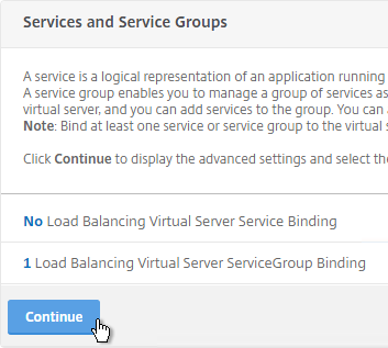
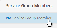
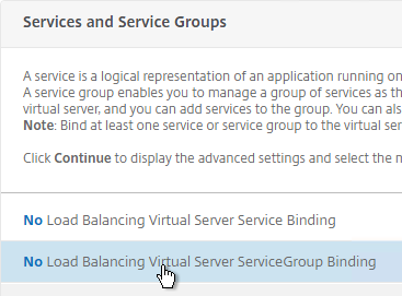
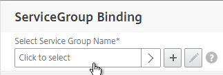
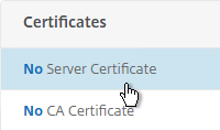
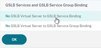
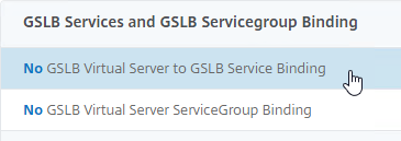
- On the left, click where it says No GSLB Virtual Server to GSLB Service Binding.
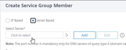
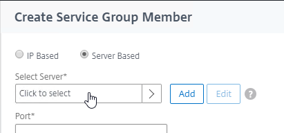
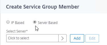
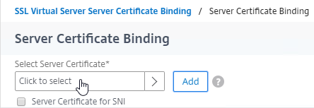
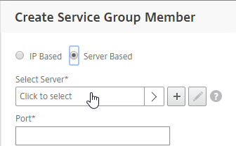
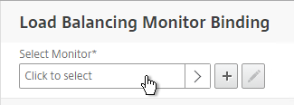
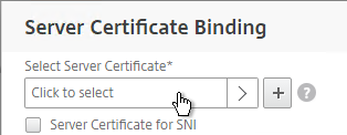
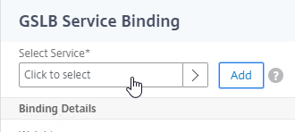
- Click where it says Click to select.

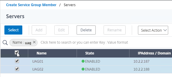
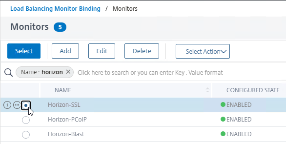
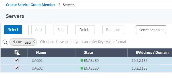
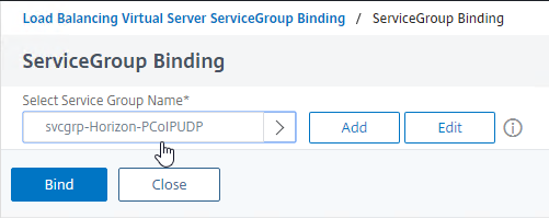
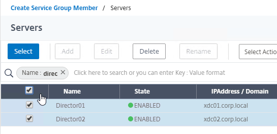
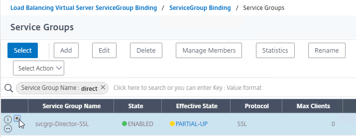
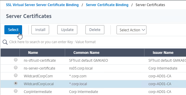
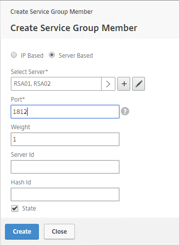
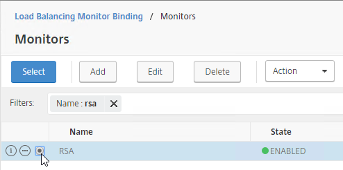
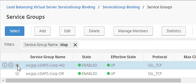
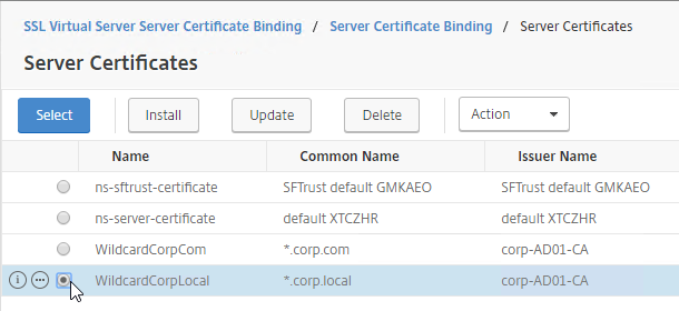
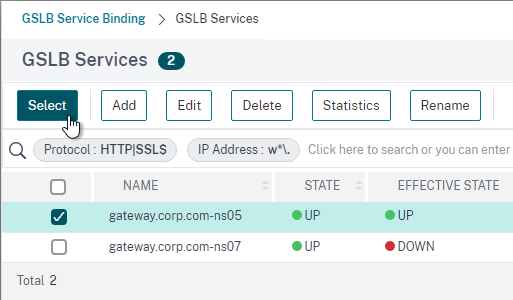
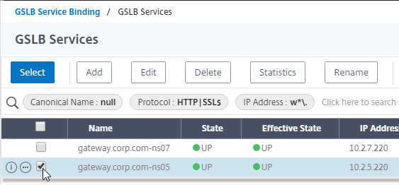
- Check the box next to the active GSLB Service and click Select.
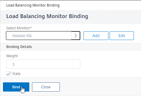
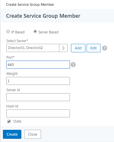
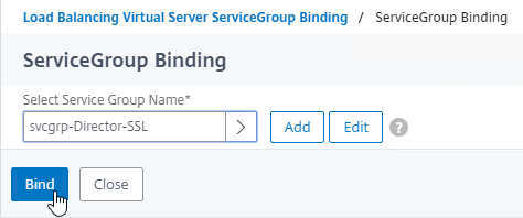
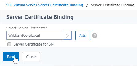
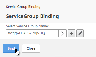
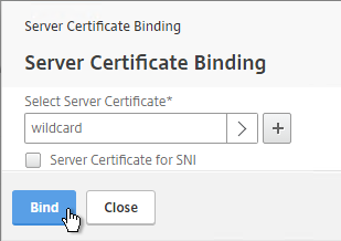
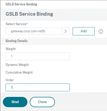
- In the Order box, enter 1. Click Bind.
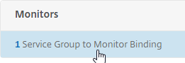
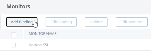
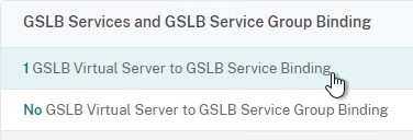
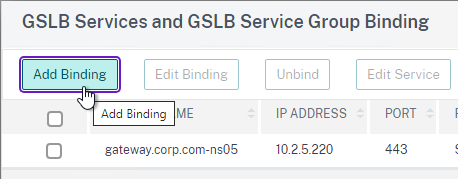
- To add another GSLB Service Binding, on the left, click where it says 1 GSLB Virtual Server to GSLB Service Binding.
- Click Add Binding.
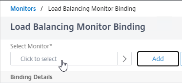
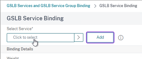
- Click where it says Click to select.
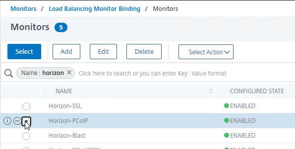
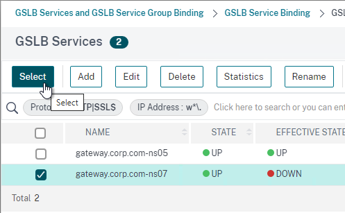
- Check the box next to a passive GSLB Service and then click Select at the top of the page.
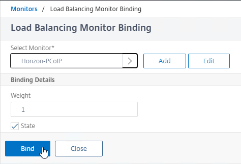
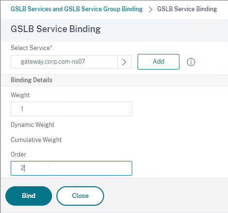
- In the Order box, enter 2 so that this GSLB Service is only used if all Order 1 GSLB Services are down. Click Bind.
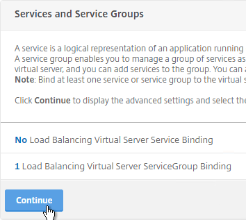
- Click OK to close the GSLB Services and GSLB Service Group Binding section.
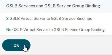
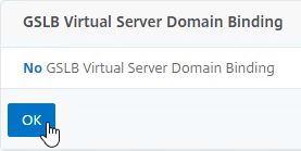
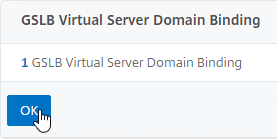
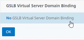
- On the left, click where it says No GSLB Virtual Server Domain Binding.
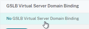
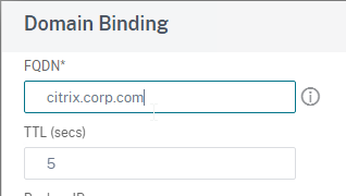
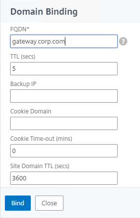
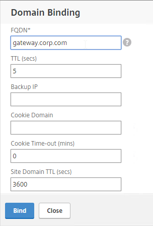
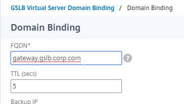
- Enter the FQDN that this GSLB Virtual Server will resolve.
- Click Bind.
- If you are doing CNAME (e.g., citrix.corp.com CNAME to citrix.gslb.corp.com, then add domain bindings for both the main FQDN and the CNAME FQDN. Click Close when done.
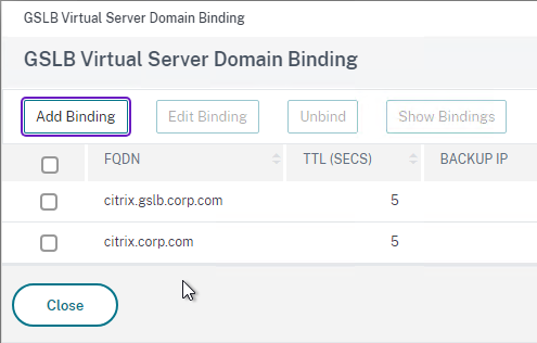
- Click OK to close the GSLB Virtual Server Domain Binding section.
- Click OK to close the ADNS Service section.
- With GSLB Services assigned to different Order numbers, it is not necessary to configure Backup Virtual Server.
- If you bound multiple GSLB Services to a single Order number, then you might want to adjust Method and Persistence.
- Click Done to finish creating the GSLB Virtual Server.

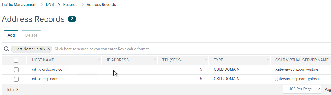
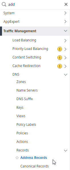
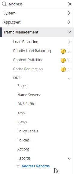
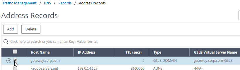
- On the left, if you expand Traffic Management > DNS, expand Records, and click Address Records…
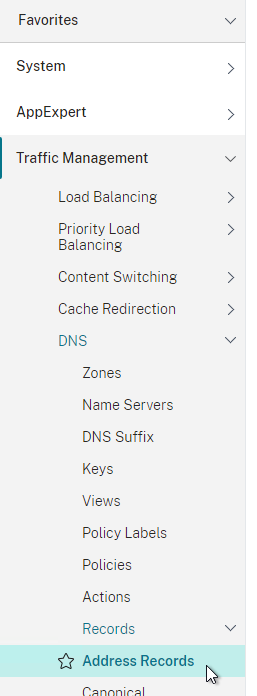
- You’ll see a new DNS record for the GSLB domain you just configured. Notice it is marked as GSLB DOMAIN, and has a default TTL of 5 seconds. You can also see which GSLB Virtual Server it is bound to.
- Configure an identical GSLB Virtual Server on the other NetScaler ADC appliance pair. Both NetScaler ADC pairs must be configured identically. You can use Traffic Management > GSLB > Dashboard > View GSLB Configuration to copy the add/set/bind gslb vserver commands from this appliance to other NetScaler ADC appliances.
Configure Active/Passive GSLB in NetScaler ADC 13.0 and older
Passive Virtual Server
- On the left, expand Traffic Management, expand GSLB, and click Virtual Servers.

- On the right, click Add.

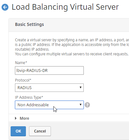
- In the Basic Settings section, do the following:
- Give the Passive GSLB Virtual Server a descriptive name.
- Set the Service Type to SSL to match the GSLB Services that you will bind to this Virtual Server.
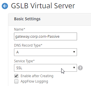
- Click OK to close the Basic Settings section.

- On the left, click where it says No GSLB Virtual Server to GSLB Service Binding.

- Click where it says Click to select.

- Check the box next to an existing Passive GSLB Service, and then click the blue Select button at the top of the screen.
- Click Bind.
- Click OK to close the GSLB Virtual Server GSLB Service Binding section.
- Click OK to close the GSLB Virtual Server Domain Binding section. The DNS name is bound to the Active Virtual Server, not the Passive Virtual Sever.
- Click OK to close the ADNS Service section.
- Click Done to finish creating the Passive GSLB Virtual Server.

Active Virtual Server
- On the left, expand Traffic Management, expand GSLB, and click Virtual Servers.
- On the right, click Add.

- In the Basic Settings section, do the following:
- Give the Active GSLB Virtual Server a descriptive name.
- Set the Service Type to SSL to match the GSLB Services that you will bind to this Virtual Server.
- Click OK to close the Basic Settings section.

- On the left, click where it says No GSLB Virtual Server to GSLB Service Binding.
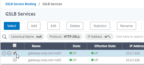
- Click where it says Click to select.
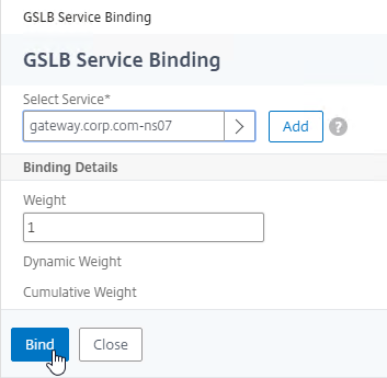
- Check the box next to an existing Active GSLB Service, and click Select.
- Click Bind.

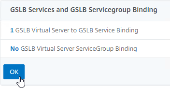
- Click OK to close the GSLB Virtual Server GSLB Service Binding section.

- On the left, click where it says No GSLB Virtual Server Domain Binding.

- In the Domain Binding page, do the following:
- Enter the FQDN that GSLB will resolve.
- Click Bind.
- Click OK to close the GSLB Virtual Server Domain Binding section.
- Click OK to close the ADNS Service section.

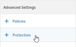
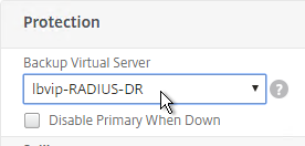
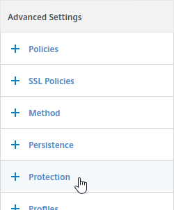
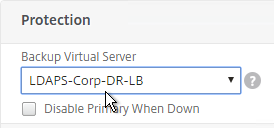
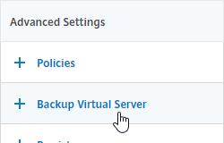
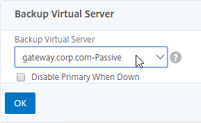
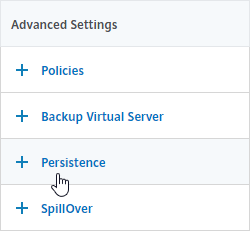
- On the right, in the Advanced Settings section, click Backup Virtual Server to add it to the left.
- On the left, in the Backup Virtual Server section, select the Passive GSLB Virtual Server, and click OK.
- Click Done when done creating the Active GSLB Virtual Server.

- On the left, if you expand Traffic Management > DNS, expand Records, and click Address Records…
- On the right, you’ll see a new DNS record for the GSLB domain you just configured. Notice the Type is GSLB DOMAIN, and has a default TTL of 5 seconds. You can also see which GSLB Virtual Server it is bound to.

- Configure identical GSLB Virtual Servers on the other Citrix ADC appliance pair. Both Citrix ADC pairs must be configured identically. You can use Traffic Management > GSLB > Dashboard > View GSLB Configuration to copy the add/set/bind gslb vserver commands from this appliance to other Citrix ADC appliances.
Configure Active/Active GSLB
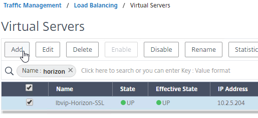
- On the left, expand Traffic Management, expand GSLB, and click Virtual Servers.
- On the right, click Add.
- In the Basic Settings section, do the following:
- Give the GSLB Virtual Server a descriptive name.
- Set the Service Type to SSL to match the GSLB Sevices you intend to bind.
- You can optionally check the box for Send all “active” service IPs in response (MIR). By default, GSLB only gives out one IP address per DNS query. This checkbox always returns all IPs, but the IPs are ordered based on the GSLB Load Balancing Method and/or GSLB Persistence.
- A new DNS feature called ECS will contain the actual DNS client IP. This dramatically improves the accuracy of determining a user’s location. Without this setting, GSLB can only see the IP address of the user’s configured DNS server instead of the real client IP. Check the box next to Respond with ECS option to enable ECS for site persistence.
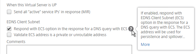
set gslb vserver <gslb_vserver> -ECS ENABLED
- Click OK to close the Basic Settings section.

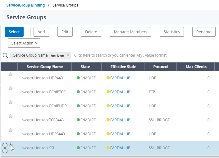
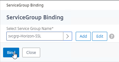
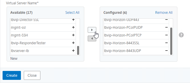
- On the left, click where it says No GSLB Virtual Server to GSLB Service Binding.

- Click where it says Click to select.
- Check the boxes next to multiple existing GSLB Services, and click Select.
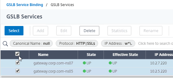
- Click Bind.
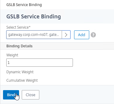
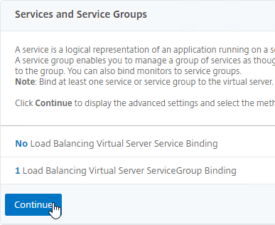
- Click OK to close the GSLB Virtual Server GSLB Service Binding section.

- On the left, click where it says No GSLB Virtual Server Domain Binding.
- Enter the FQDN that this GSLB Virtual Server will resolve.
- Click Bind.
- Click OK to close the GSLB Virtual Server Domain Binding section.

- Click OK to close the ADNS Service section.

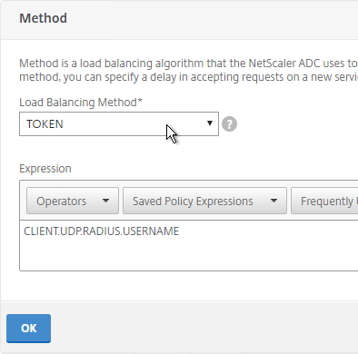
- On the left, in the Method section, click the pencil icon.
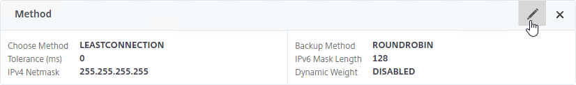
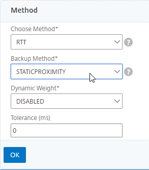
- For poximity load balancing, change the Choose Method drop-down to RTT with STATICPROXIMITY as backup.
- RTT = Round Trip Time. Each ADC appliance sends a ping to the user’s DNS server. Whichever ADC appliance gets the fastest response determines the site of the GSLB Service. RTT requires that ADC be able to ping anything on the Internet so adjust firewall rules accordingly.
- STATICPROXIMITY requires that the Geo Location database has already been installed on the appliance.
- Click OK to close the Method section.
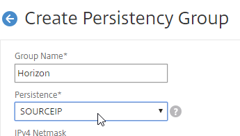
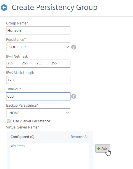
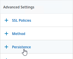
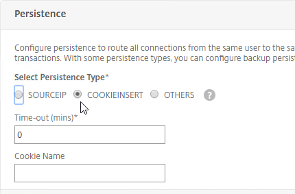
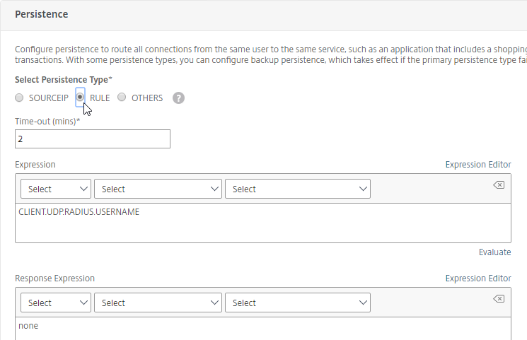
- On the right, in the Advanced Settings column, click Persistence to add it to the left.
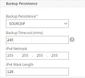
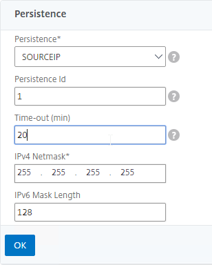
- On the left, at the bottom of the page in the Persistence section, change the Persistence drop-down to Source IP.
- Enter a Persistence Id.
- The Persistence ID signifies the persistence table that each ADC pair shares across the MEP connection.
- Each active/active GSLB Virtual Server should have a different Persistence ID (different persistence table).
- When you configure the same GSLB Virtual Server on each Citrix ADC pair, specify the same Persistence ID so every Citrix ADC has the same persistence information for this particular GSLB Virtual Server.
- In the Time-out field, enter the Persistence Time-out. This is typically the same or longer than the webpage timeout.
- Click OK to close the Persistence section.
- Click Done to finish creating the GSLB Virtual Server.

- On the left, if you expand Traffic Management > DNS, expand Records, and click Address Records…
- You’ll see a new DNS record for the GSLB domain you just configured. Notice it is marked as GSLB DOMAIN, and has a default TTL of 5 seconds. You can also see which GSLB Virtual Server it is bound to.
- Configure an identical GSLB Virtual Server on the other Citrix ADC appliance pair. Both Citrix ADC pairs must be configured identically. You can use Traffic Management > GSLB > Dashboard > View GSLB Configuration to copy the add/set/bind gslb vserver commands from this appliance to other Citrix ADC appliances.
GSLB Configuration Synchronization Script
Manual GSLB Synchronization
- The synchronization script requires SSH to be enabled on your GSLB Site IPs.
- Ports TCP 3008, TCP 3010, and TCP 22 must be opened from the local NSIP to the remote GSLB Site IP. The source IP is NSIP, not SNIP.
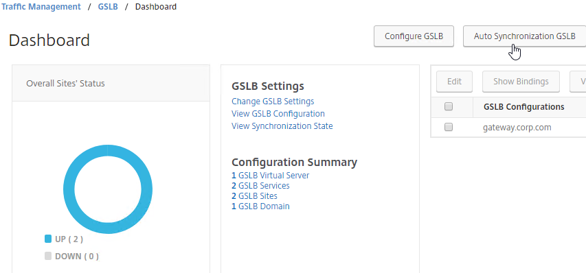
- To manually run the script that syncs GSLB configuration from one GSLB Site to another, on the left, expand Traffic Management, expand GSLB, and click Dashboard.
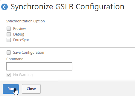
- On the right, click the button labelled Auto Synchronization GSLB.
- Use the check boxes on the top, if desired. It’s usually a good idea to Preview the changes before applying them.
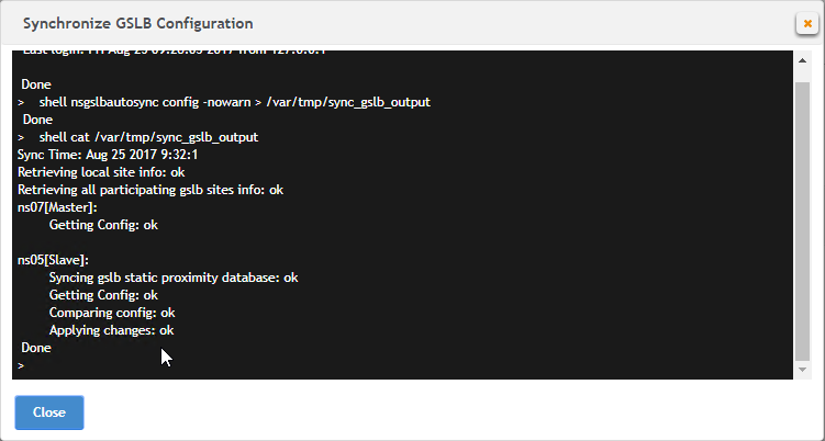
- Then click Run to begin synchronization.
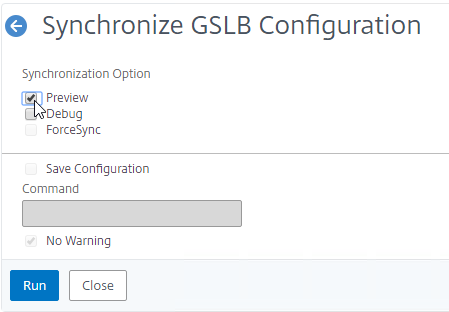
- Click Close.
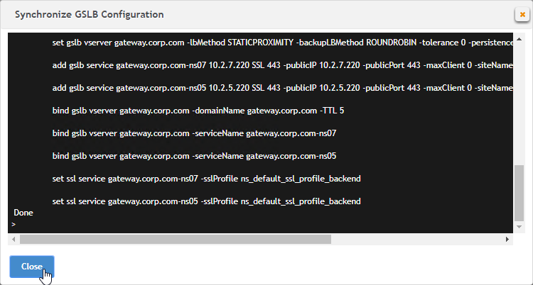
- You can Run it again without previewing it. It seems to take several seconds to complete.
Automatic GSLB Synchronization
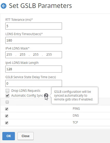
- There is an automatic GSLB Configuration Sync feature, which automatically syncs the GSLB config every 15 seconds. To enable it on the master appliance, go to Traffic Management > GSLB > Dashboard. On the right, click Change GSLB settings.
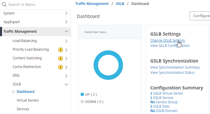
- Check the box next to Automatic Config Sync. Only enable this on the one appliance where you are configuring GSLB, and want that GSLB config synced to other appliance.
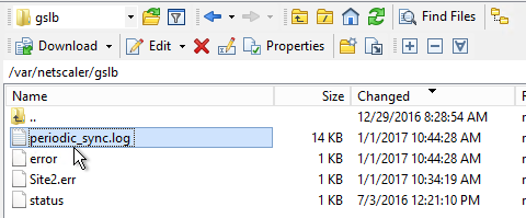
- The automatic sync log can be found at /var/netscaler/gslb/periodic_sync.log.
Some notes regarding GSLB Sync:
- When syncing GSLB Services, it tries to create Load Balancing Server objects on the remote appliance. If the GSLB Service IP matches an existing Load Balancing Server object, then the GSLB sync will fail. Check the Sync logs for details. You’ll have to delete the conflicting Load Balancing Server object before GSLB Sync works correctly.
- GSLB Sync runs as a script on the BSD shell and thus always uses the NSIP as the source IP.
- GSLB Sync connects to the remote GSLB Site IP on TCP 3008 (if RPC is Secure) and TCP 22.
Test GSLB
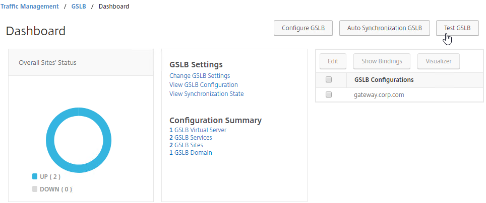
- You can test GSLB DNS name resolution from the GUI by going to Traffic Management > GSLB > Dashboard, and on the right, click the button labelled Test GSLB.
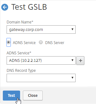
- Select a GSLB Domain Name.
- Select an ADNS Service IP to test it from, and click Test.
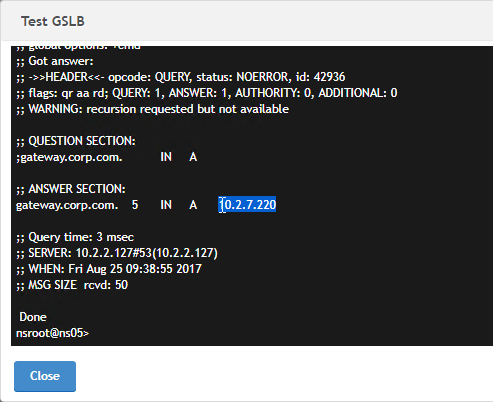
- The test performs a dig against the ADNS IP. Verify that the response contains the IP address you expected.
- Another method of testing GSLB is to simply point nslookup to the ADNS services and submit a DNS query for one of the DNS names bound to a GSLB vServer. Run the query multiple times to make sure you’re getting the response you expect.
- The syntax is “nslookup <DNS_name> <ADNS_IP>”. The second argument specifies the DNS server that you send the DNS Query to.
- The Citrix ADC ADNS services at both GSLB sites should be giving the same response.
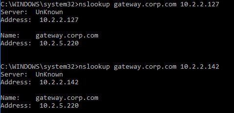
- To simulate a failure, if the GSLB Service IP is a Citrix ADC Load Balancing, Content Switching, or Citrix Gateway IP, you can disable the Virtual Server.
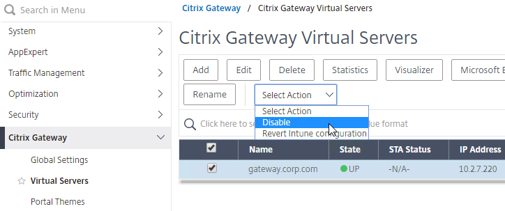
- Then the responses should change. Verify on both ADNS services.
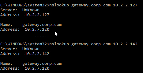
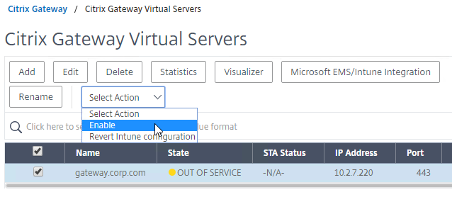
- Re-enable the Virtual Server, and the responses should return to normal.
DNS Delegation
If you are enabling GSLB for the domain gateway.corp.com, you’ll need to create a delegation at the server that is hosting the corp.com DNS zone. For public GSLB, you need to edit the public DNS zone for corp.com.
DNS Delegation instructions will vary depending on what product is hosting the public DNS zone. This section details Microsoft DNS, but it should be similar in BIND or web-based DNS products.
There are two ways to delegate GSLB-enabled DNS names to Citrix ADC ADNS:
- Delegate the individual record – For example, delegate gateway.corp.com.
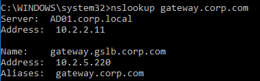
- Delegate an entire subzone – For example, delegate the subzone gslb.corp.com. Then create a CNAME record in the parent DNS zone for gateway.corp.com that is aliased to gateway.gslb.corp.com. For additional delegations, simply create more CNAME records.
- The incoming DNS query to the ADNS listener is for gateway.gslb.corp.com and not gateway.corp.com. You’ll need to bind gateway.gslb.corp.com to your GSLB Virtual Server. You can bind multiple FQDNs to a single GSLB Virtual Server.
A delegation consists of the following DNS records:
- A records (host records) that resolve to each Citrix ADC ADNS IP address. If you have two ADC pairs participating in GSLB, then you’ll need one A record for each ADC pair.
- The A record names are typically something like ns1.corp.com and ns2.corp.com, just like you would name any other DNS server.
- You only create the A records once. The A records for ADNS services can be used by multiple delegations.
- These A records for ADNS are sometimes called glue records.
- NS records for each delegation. The NS records point to the A records that resolve to the ADC ADNS IP addresses. If you have two ADC ADNS IP addresses, then you need two NS records for each delegation.
- When delegating individual records, you create separate NS records for each delegation. If you have two ADNS listeners, then you need two NS records for each delegation.
- When delegating a subzone, you only need NS records for the subzone. To GSLB-enable a DNS name, you create a CNAME that aliases to a record under the subzone.
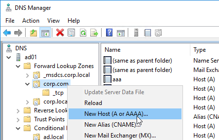
Delegate an individual DNS record
- Run DNS Manager.
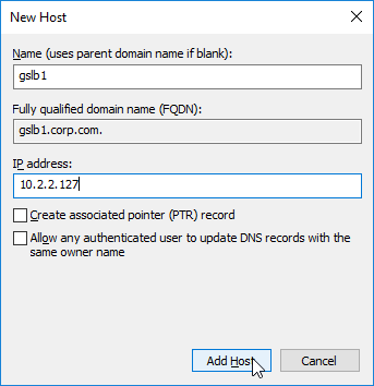
- First, create Host Records pointing to the ADNS services running on the Citrix ADC pairs in each data center. These host records for ADNS are used for all GSLB delegations no matter how many GSLB delegations you need to create. These are sometimes called glue records.
- The first Host record is gslb1, (or similar) and should point to the ADNS service (Public IP) on one of the Citrix ADC appliances.
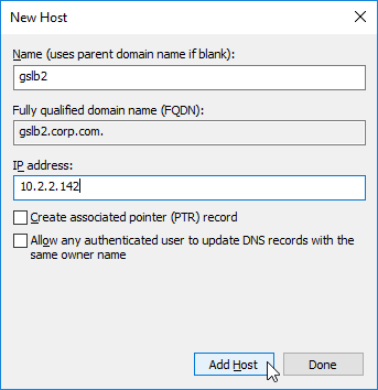
- The second Host record is gslb2, and should point to the ADNS Service (public IP) on the other Citrix ADC appliance.
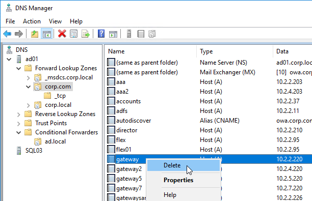
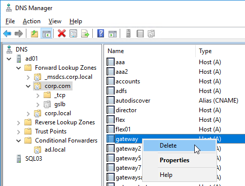
- If you currently have a host record for the service that you are delegating to GSLB (e.g. gateway.corp.com), delete it.
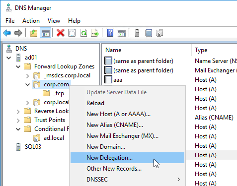
- Right-click the parent DNS zone, and click New Delegation.
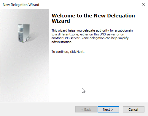
- In the Welcome to the New Delegation Wizard page, click Next.
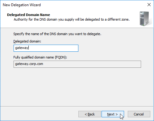
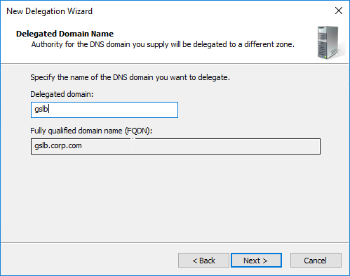
- In the Delegated Domain Name page, enter the left part of the DNS record that you are delegating (e.g. gateway for gateway.corp.com). Click Next.
- In the Name Servers page, click Add.
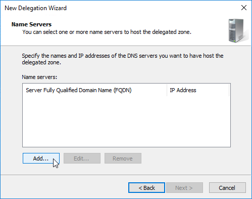
- This is where you specify gslb1.corp.com and gslb2.corp.com as delegated name servers. Enter gslb1.corp.com, and click Resolve. Then click OK. If you see a message about the server not being authoritative for the zone, ignore the message. Note: you only add one name server at a time.
- Then click Add to add the other GSLB ADNS server.
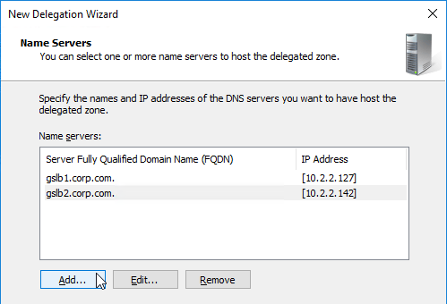
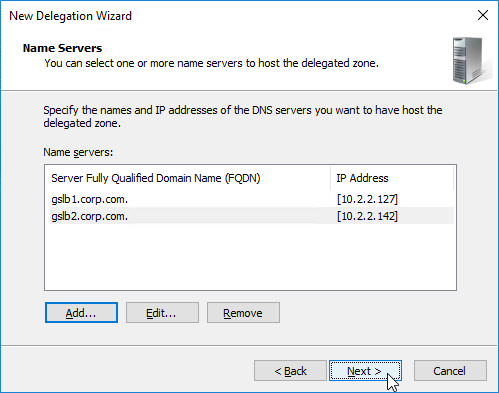
- Once both ADNS servers are added to the list, click Next.
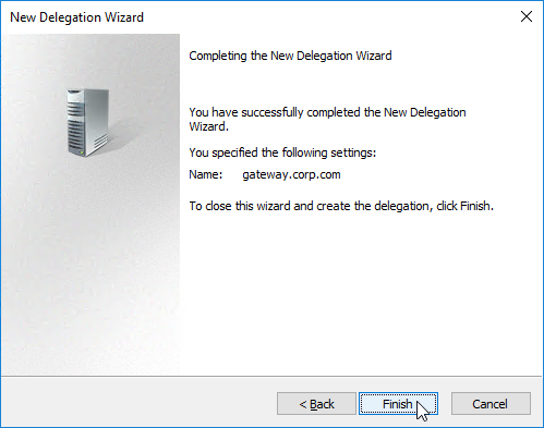
- In the Completing the New Delegation Wizard page, click Finish.
- The delegation is shown in the DNS Manager console.
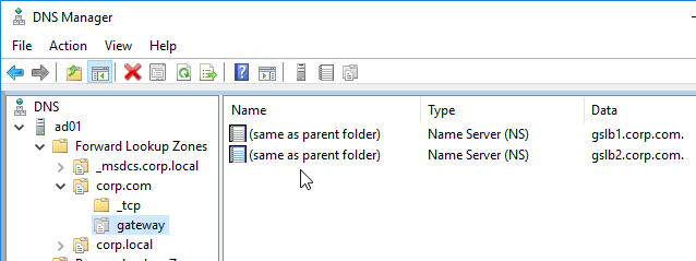
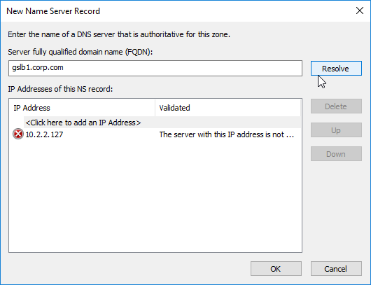
- For proper delegation, the Name Server records should also be added to Citrix ADC. (source = Citrix CTX241493 Citrix Response on DNS Flag Day)
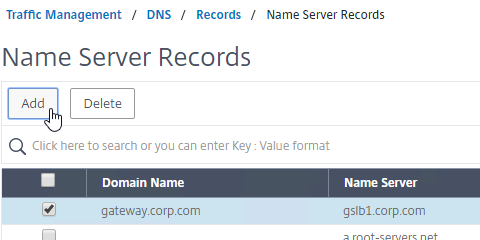
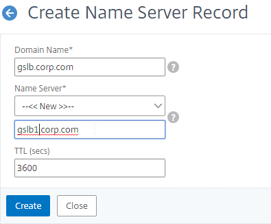
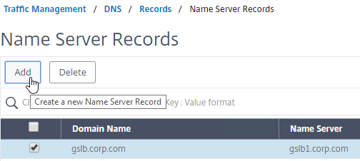
- On the GSLB Citrix ADC appliances, expand Traffic Management, expand DNS, expand Records, and click Name Server Records.
- On the right, click Add.

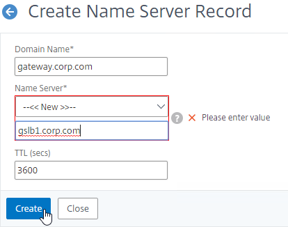
- In the Domain Name field, enter the name of the delegated DNS name (e.g. gateway.corp.com).
- In the Name Server field, leave it set to –<< New >>–, and enter one of the FQDNs for your GSLB ADNS services. This is one of the glue records you created earlier.
- Click Create.
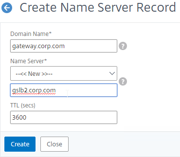
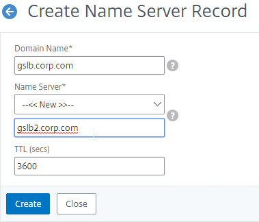
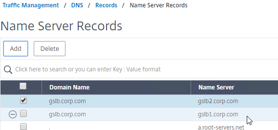
- Add another Name Server Record for the same domain name. But this time, enter the second GSLB ADNS FQDN. Repeat this process until all GSLB ADNS FQDNs are specified.
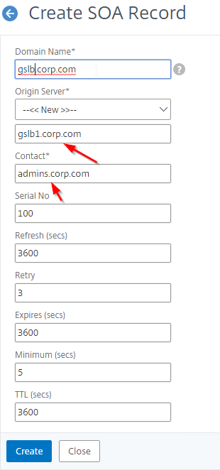
- Also add an SOA record for the delegation. If you are delegating individual records, then you will need an SOA for each record. If you are delegating a subzone, you only need an SOA record for the subzone.
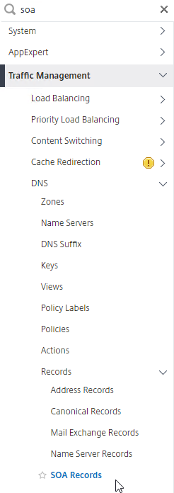
- On the left, in the menu, go to Traffic Management > DNS > Records > SOA Records.
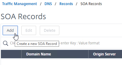
- On the right, click Add.
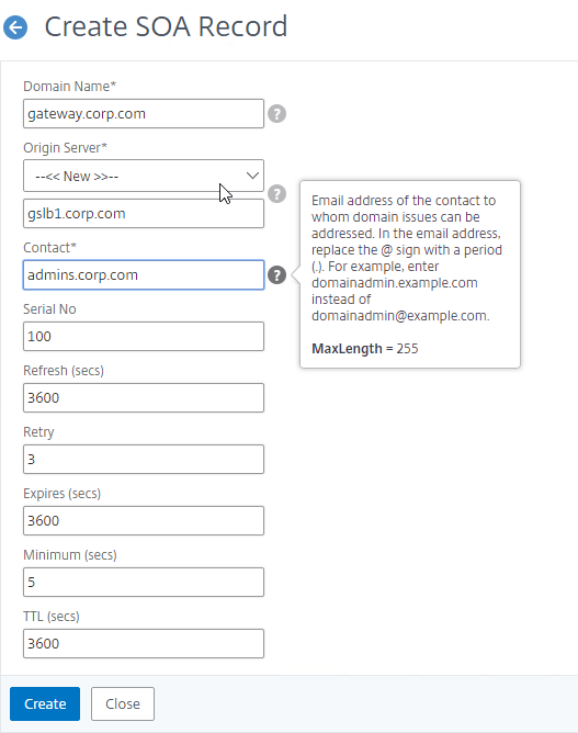
- In the Domain Name field, enter the FQDN that you delegated to NetScaler. This can be an individual record, or a sub-zone.
- In the Origin Server field, leave it set to –<< New >> — and then enter the FQDN that resolves to one of your ADNS listeners. It doesn’t matter which one you enter.
- In the Contact field, enter an email address that is publicly viewable. Replace the @ symbol with a period.
- Click Create.
- Repeat this on the other ADCs that are participating in GSLB for this delegated DNS name.
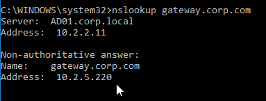
- If you run nslookup against your Microsoft DNS server, it will respond with Non-authoritative answer. That’s because it got the response from Citrix ADC, and not from the original DNS server that you send the request to.
Delegate a Sub-zone
- Run DNS Manager.
- First, create Host Records pointing to the ADNS services running on the Citrix ADC pairs in each data center. These are sometimes called glue records.
- The first Host record is gslb1 (or similar), and should point to the ADNS service (Public IP) on one of the Citrix ADC appliances.
- The second Host record is gslb2, and should point to the ADNS Service (public IP) on the other Citrix ADC appliance.
- Right-click the parent DNS zone, and click New Delegation.
- In the Welcome to the New Delegation Wizard page, click Next.
- In the Delegated Domain Name page, enter the left part of the DNS sub-zone that you are delegating (e.g. gslb for gslb.corp.com). Click Next.
- In the Name Servers page, click Add.
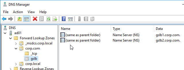
- This is where you specify gslb1.corp.com and gslb2.corp.com. Enter gslb1.corp.com, and click Resolve. Then click OK. If you see a message about the server not being authoritative for the zone, ignore the message. Note: you only add one name server at a time.
- Then click Add to add the other GSLB ADNS server.
- Once both ADNS servers are added to the list, click Next.
- In the Completing the New Delegation Wizard page, click Finish.
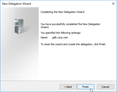
- The sub-zone delegation is shown in the DNS Manager console.
- For proper delegation, the Name Server records should also be added to Citrix ADC. (source = Citrix CTX241493 Citrix Response on DNS Flag Day)
- On the GSLB Citrix ADC appliances, expand Traffic Management, expand DNS, expand Records, and click Name Server Records.
- On the right, click Add.
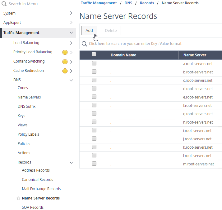
- In the Domain Name field, enter the name of the delegated sub-domain (e.g. gslb.corp.com).
- In the Name Server field, leave it set to –<< New >>–, and enter one of the FQDNs for your GSLB ADNS services. This is one of the glue records you created earlier.
- Click Create.
- Add another Name Server Record for the same domain name. But this time, enter the second GSLB ADNS FQDN.
- Repeat this process until all GSLB ADNS FQDNs are specified.
- Also add an SOA record for the delegation. If you are delegating individual records, then you will need an SOA for each record. If you are delegating a subzone, you only need an SOA record for the subzone.
- On the left, in the menu, go to Traffic Management > DNS > Records > SOA Records.
- On the right, click Add.
- In the Domain Name field, enter the FQDN that you delegated to NetScaler. This can be an individual record, or a sub-zone.
- In the Origin Server field, leave it set to –<< New >> — and then enter the FQDN that resolves to one of your ADNS listeners. It doesn’t matter which one you enter.
- In the Contact field, enter an email address that is publicly viewable. Replace the @ symbol with a period.
- Click Create.
- Repeat this on the other ADCs that are participating in GSLB for this delegated DNS name.
Each GSLB-enabled DNS name must be CNAME’d to GSLB:
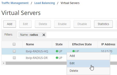
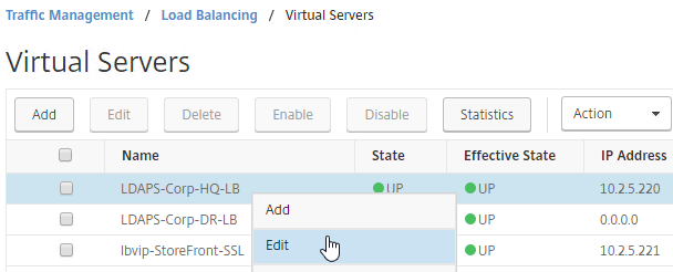
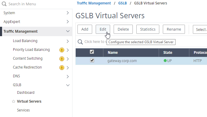
- In Citrix ADC, go to Traffic Management > GSLB > Virtual Servers, and edit your GSLB Virtual Server.
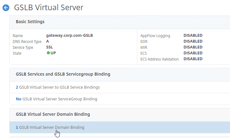
- On the left, click in the GSLB Virtual Server Domain Binding section.
- Click Add Binding.
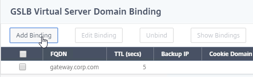
- Add a domain binding for the CNAME’d DNS name. For example, if the original DNS name is gateway.corp.com, then enter gateway.gslb.corp.com. gslb.corp.com matches the sub-zone that you delegated to Citrix ADC. Click OK.
- Repeat the Domain Binding on the other Citrix ADC appliances.
- In DNS Manager, if you currently have a host record for the service that you are delegating to GSLB (gateway.corp.com), delete it.
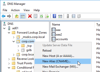
- Right-click the DNS zone, and click New Alias (CNAME).
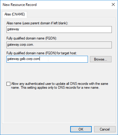
- In the Alias name field, enter the left part of the original DNS name. For gateway.corp.com, enter gateway.
- In the Fully qualified domain name (FQDN) for target host field, enter the CNAME’d DNS name that is delegated to Citrix ADC. For example, if you delegated gslb.corp.com to Citrix ADC, then enter gateway.gslb.corp.com. The GSLB Virtual Server must be configured to match this longer DNS name.
- Click OK.
- If you run nslookup for the delegated DNS name, it will first CNAME to the longer name, and then respond with the IP address returned by Citrix ADC GSLB.
- You can repeat these steps to delegate (CNAME) additional DNS names to Citrix ADC GSLB.