Navigation
- Overview
- AAA Virtual Server
- Login Schema
- Advanced Authentication Policies
- Authentication Policy Label
- nFactor for NetScaler Gateway
- Sample Configurations
Overview
nFactor lets you configure an unlimited number of authentication factors. You are no longer limited to just two factors. Each authentication factor performs the following tasks:
- nFactor requests credentials from the user. These credentials can be anything supported by NetScaler including:
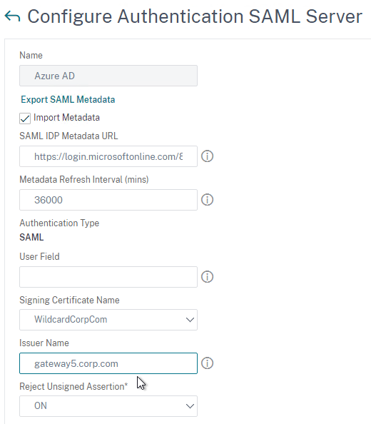
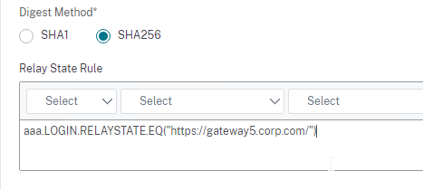
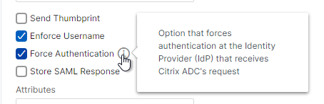
- SAML
- Certificate
- oAuth
- Kerberos
- Forms-based authentication (traditional web-based logon page) for LDAP, RADIUS, etc.
- Multiple passwords can be collected with one form.
- Or prompt the user multiple times throughout the authentication chain.
- The logon page can contain a domain drop-down.
- nFactor evaluates the credentials. The results can be:
- Authentication success
- Authentication failure
- Group extraction
- Attribute extraction from SAML, Certificate, etc.
- Based on the evaluation results, do one of the following:
- Allow access
- Use authentication evaluation results to select next factor
- Deny access
- Multiple factor evaluations can be chained together. The chosen next factor is based on the results of the prior factor. This can continue indefinitely. The next factor can do one of the following:
- Prompt the user for more credentials
- Evaluate the already entered next set of credentials
- Use policy expression to select another next factor (no authentication). This is typically used with group extraction so that groups determine the next factor.
Here are some nFactor use cases, but the combinations are almost limitless:
- Authentication method based on Active Directory group: Logon screen asks for user name only. Extract user’s groups from Active Directory. Based on user’s Active Directory groups, either ask user for certificate, or ask user for LDAP password. If LDAP, the username doesn’t need to be entered again.
- Ask for Certificate first:
- If certificate, perform LDAP
- If no certificate, perform LDAP + RADIUS
- Two-factor with passwords checked in specific order: Logon screen with two password fields. Check the first password. If the first password succeeds, then check the second password. This lets you check RADIUS before LDAP.
In NetScaler 11.0 build 62 and newer, you can configure nFactor on AAA authentication servers.
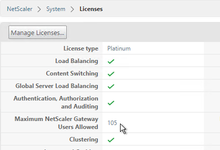
In NetScaler 11.0 build 66 and newer, you can configure nFactor in the AAA feature and bind it to NetScaler Gateway Virtual Servers. Thus NetScaler Enterprise Edition is required.
- Note: nFactor works with browser clients, but it does not work with Receiver Self-Service (native Receiver).
nFactor configuration summary (detailed instructions below):
- The first factor (Advanced Authentication Policy and Login Schema) is bound directly to a AAA Virtual Server.
- Next factors are Authentication Policy Labels that are chained to Advanced Authentication Policies in prior factors.
- Authentication Profile links AAA nFactor with NetScaler Gateway.
AAA Virtual Server
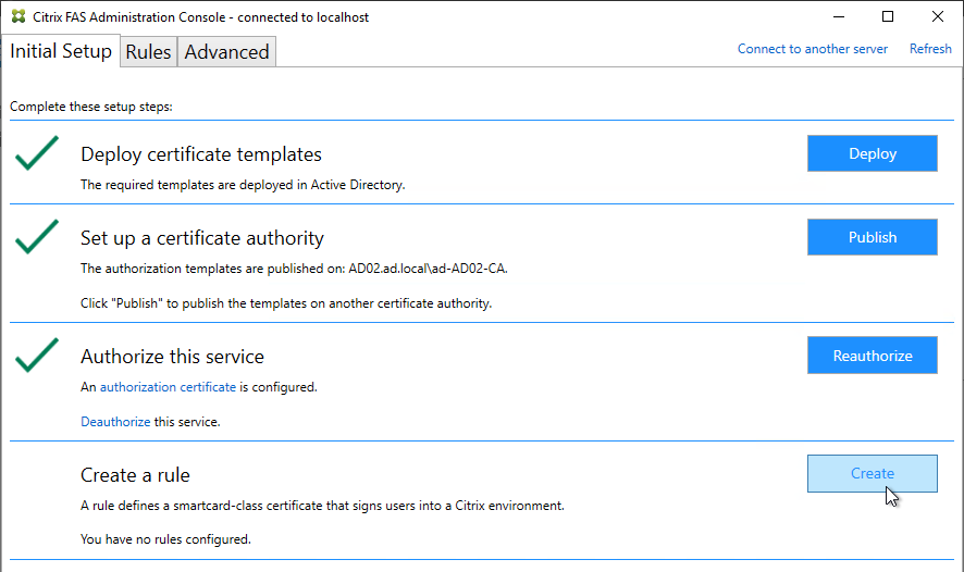
Create AAA Virtual Server
To use nFactor with NetScaler Gateway, you first configure it on a AAA Virtual Server. Then you later bind the AAA Virtual Server to the NetScaler Gateway Virtual Server.
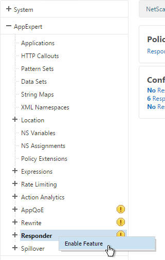
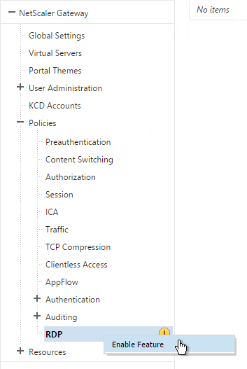
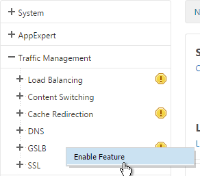
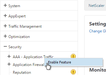
- If AAA feature is not already enabled, go to Security > AAA, right-click AAA and Enable Feature.
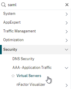
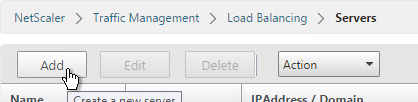
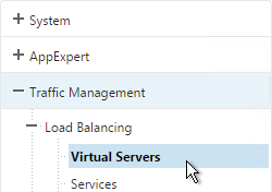
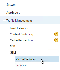
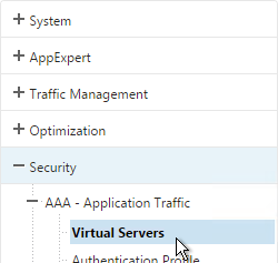
- Go to Security > AAA > Virtual Servers.
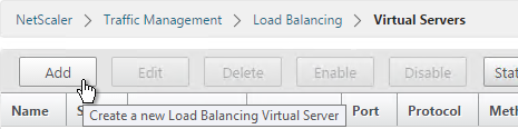
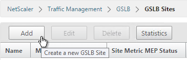
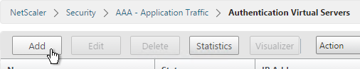
- On the right, click Add.
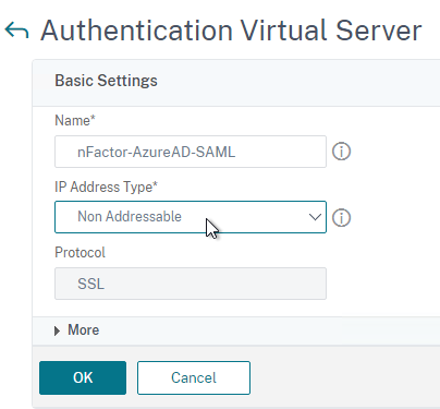
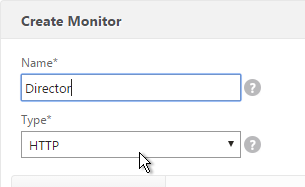
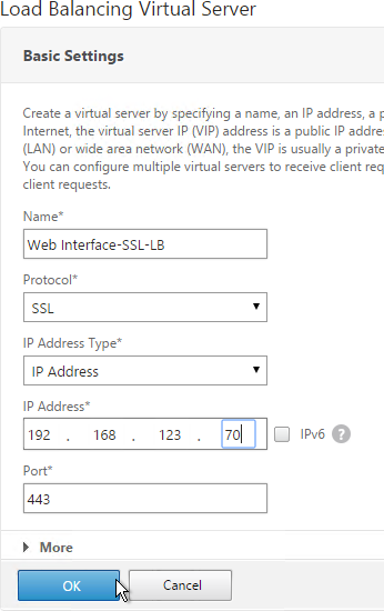
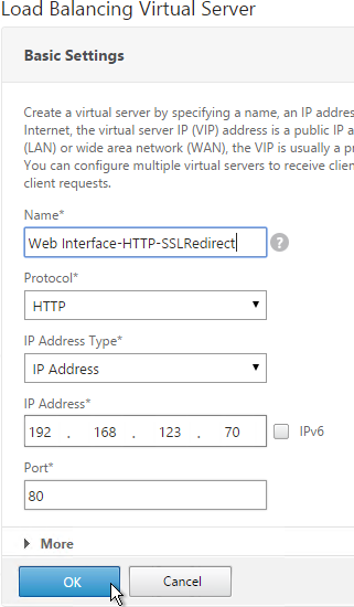
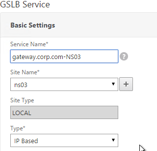
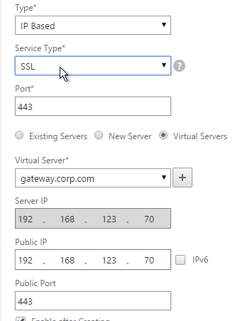
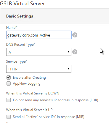
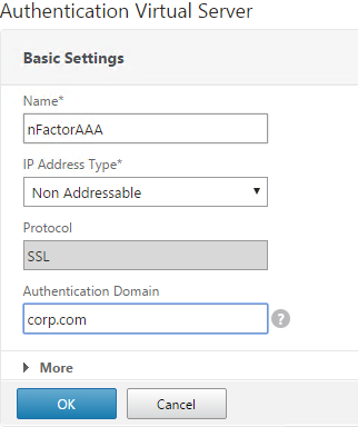
- Give the Virtual Server a name.
- If you are only using this AAA Virtual Server for NetScaler Gateway, then you can change the IP address Type to Non Addressable. It’s also possible to content switch to AAA.
- Enter an Authentication Domain and click OK.
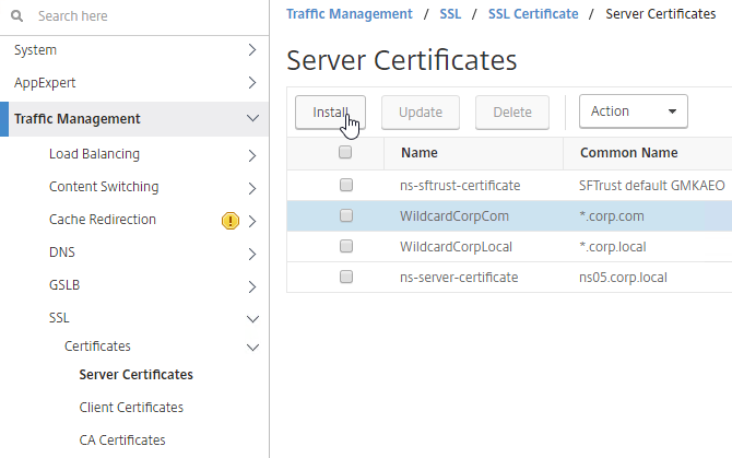
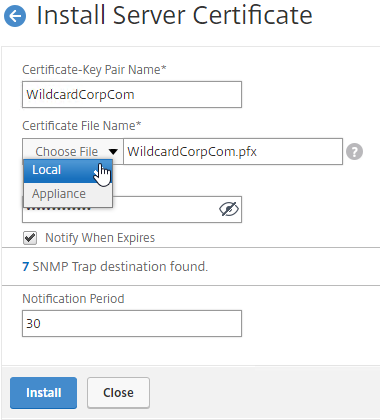
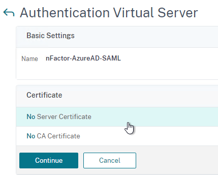
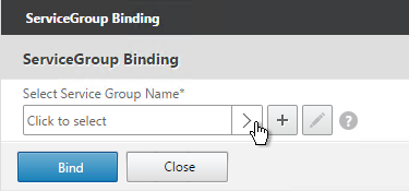
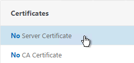
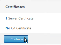
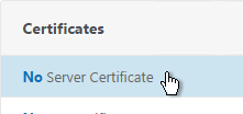
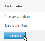
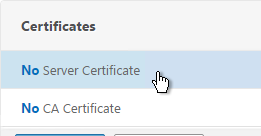
- In the Certificates section, click where it says No Server Certificate.
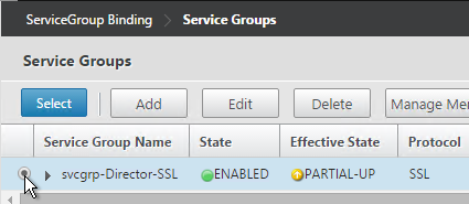
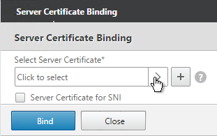
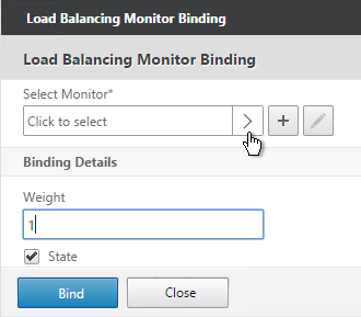
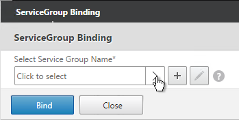
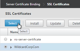
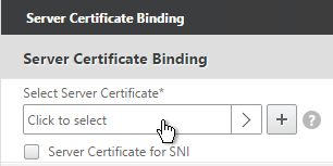
- Click to select.
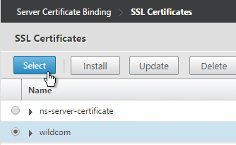
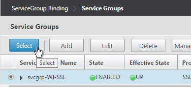
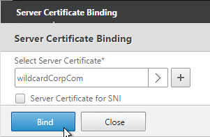
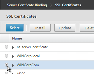
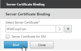
- Select a certificate for the AAA Virtual Server and click Select. Since this AAA Virtual Server is not directly addressable, the chosen certificate doesn’t matter.
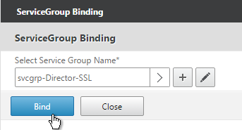
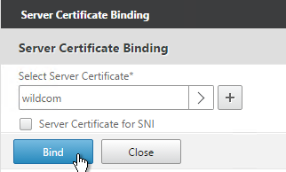
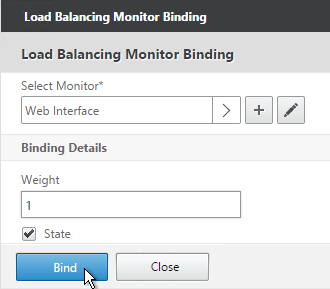
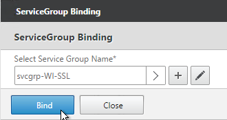
- Click Bind.
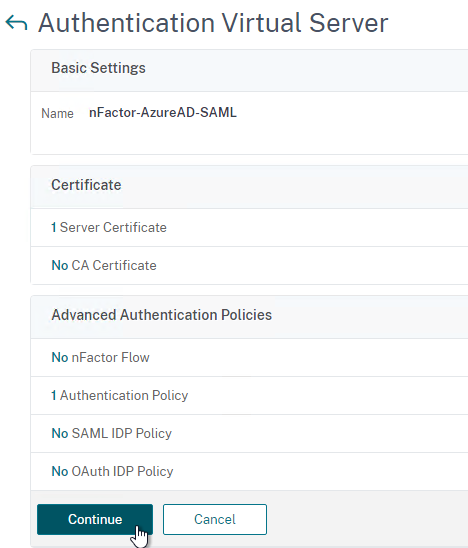
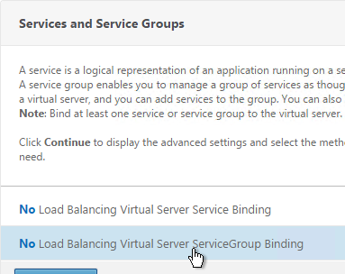
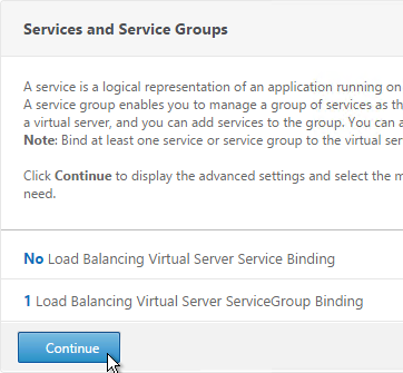
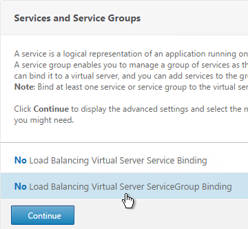
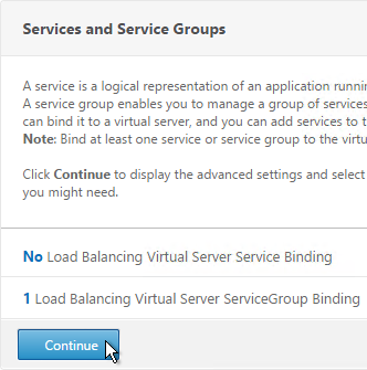
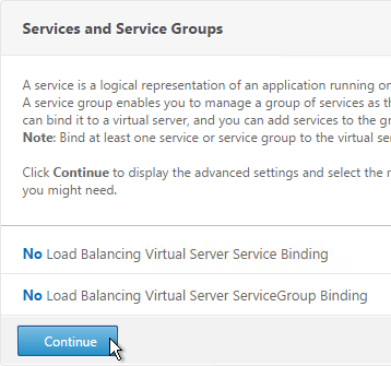
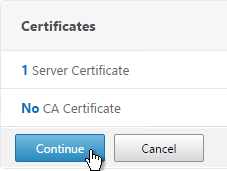
- Click Continue.
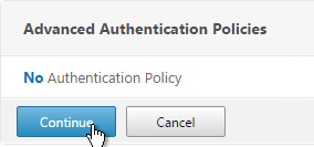
- You probably don’t have any Advanced Authentication Policies yet so just click Continue.
AAA Portal Theme
If this AAA Virtual Server is used not just for NetScaler Gateway, but also for traffic management (Load Balancing, Content Switching), then you might want to change the AAA Portal theme.
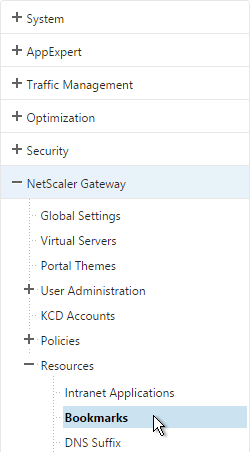
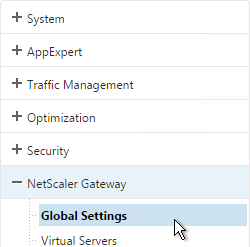
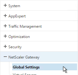
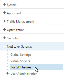
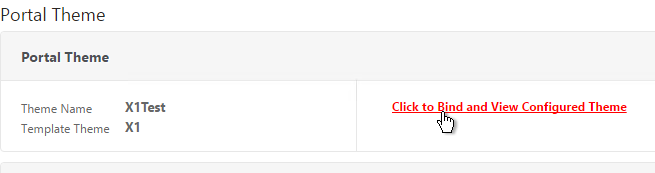
- Go to NetScaler Gateway > Portal Themes and add a theme.
- After adjusting it as desired, at the top of the portal theme editing page, Click to Bind and View Configured Theme.
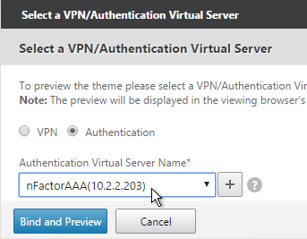
- Change the selection to Authentication.
- Use the Authentication Virtual Server Name drop-down to select the AAA Virtual Server and click Bind and Preview.
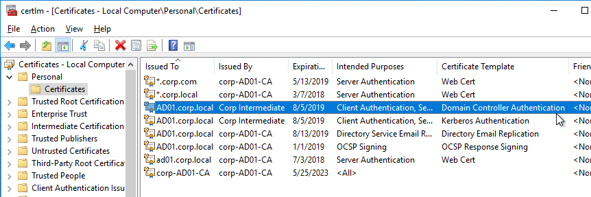
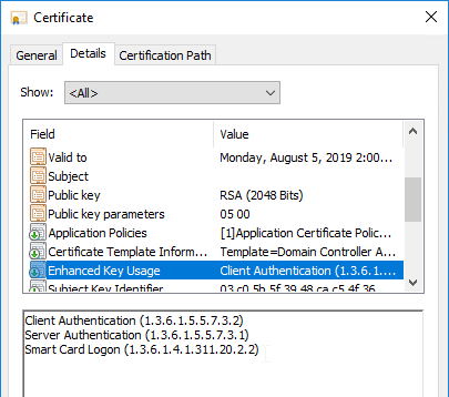
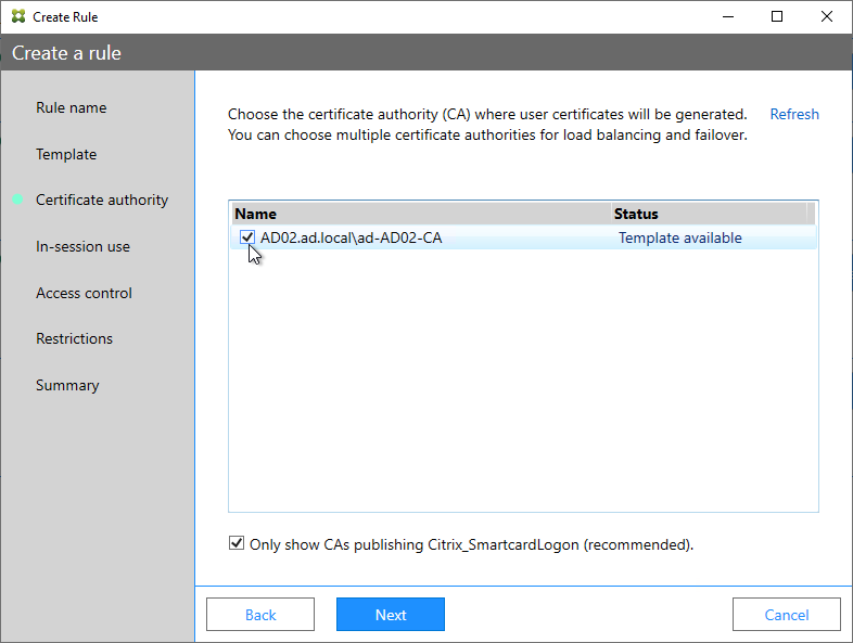
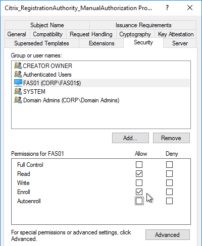
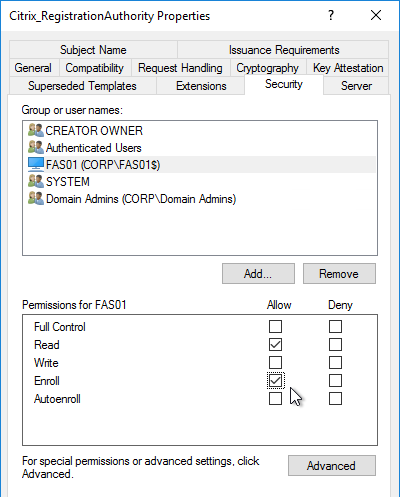
Client Certificate Authentication
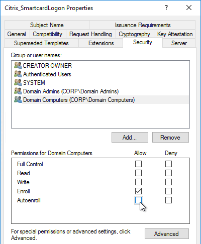
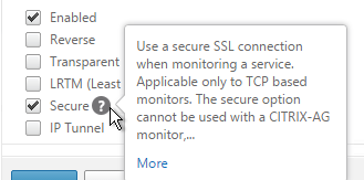
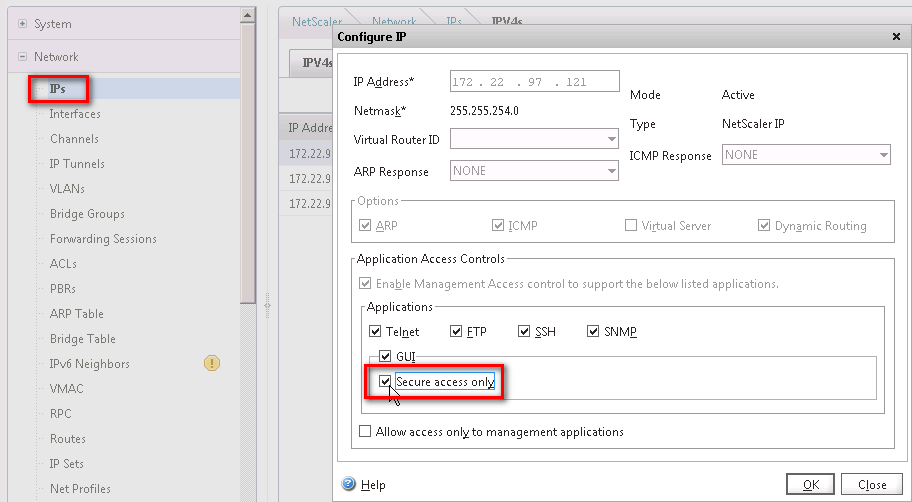
If one of your authentication Factors is certificate, then you must perform some SSL configuration on the AAA Virtual Server:
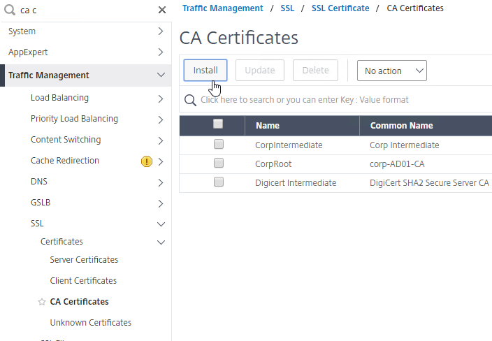
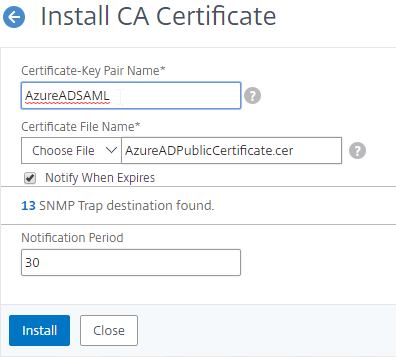
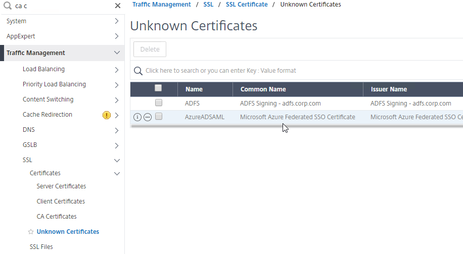
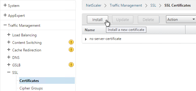
- Go to Traffic Management > SSL > Certificates and install the root certificate for the issuer of the client certificates. Root certificates do not have a key file.

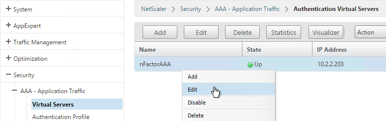
- Go to Security > AAA > Virtual Servers and edit an existing AAA Virtual Server.
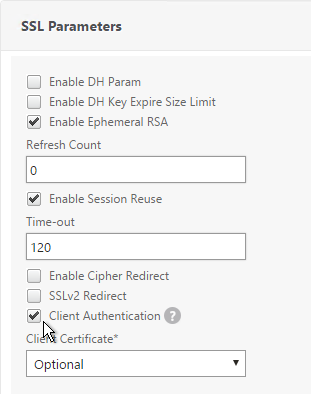
- On the left, in the SSL Parameters section, click the pencil icon.
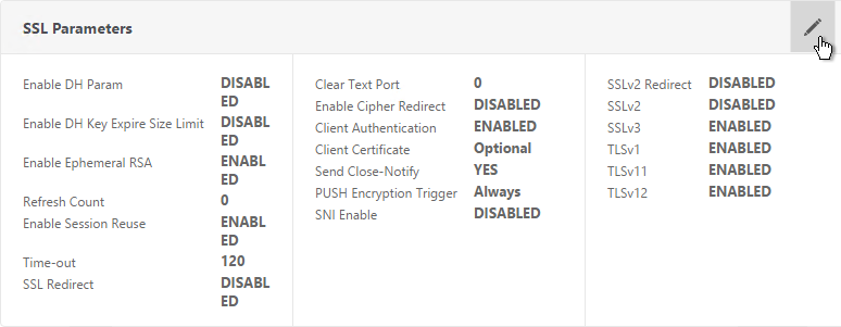
- Check the box next to Client Authentication.
- Make sure Client Certificate drop-down is set to Optional, and click OK.
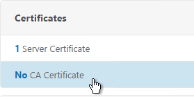
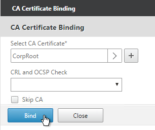
- On the left, in the Certificates section, click where it says No CA Certificate.
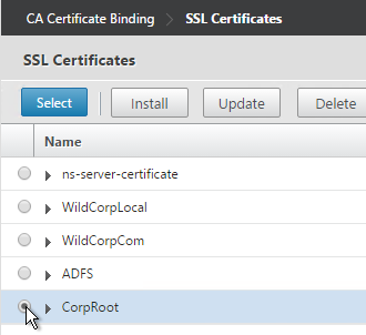
- Click to select.
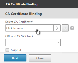
- Select the root certificate for the issuer of the client certificates and click Select.
- Click Bind.
Login Schema
Login Schema XML File
Login Schema is an XML file providing the structure of forms-based authentication logon pages.
nFactor implies multiple authentication Factors that are chained together. Each Factor can have different Login Schema pages/files. In some authentication scenarios, users could be presented with multiple logon screens.
Or you can have one Factor gather information that can be passed on to later Factors so that the later Factors don’t need to display another Login Schema. This is particularly useful for traditional two-password logon screens (LDAP + RADIUS) since each password is evaluated in a separate Factor:
- The first password is evaluated in the first factor (e.g. LDAP). If successful, then proceed to the second factor.
- The second factor (e.g. RADIUS) evaluates the second password. However, the second password has already been entered so there’s no need to ask the user for it again. To prevent a Login Schema from being shown to the user, select noschema (LSCHEMA_INT) in the Authentication Policy Label.
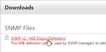
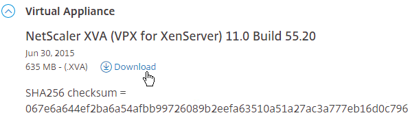
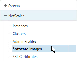
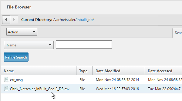
Several Login Schema .xml files are included with NetScaler under /nsconfig/loginschema/LoginSchema. You can easily duplicate and modify these files. You can also download login schemas from support.citrix.com.
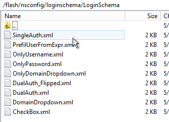
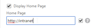
After duplicating one of the existing .xml files, you can edit it as desired. You can change the labels. Or you can configure fields to pre-fill information from previous Factors as shown below:

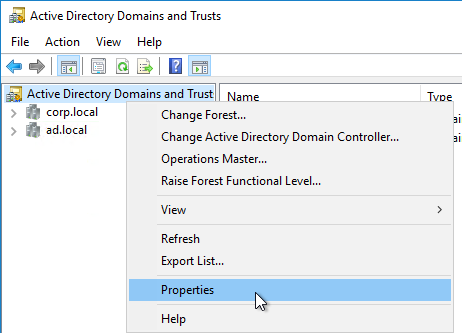
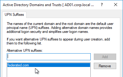
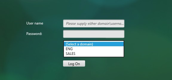
The login schema can also contain a domain drop-down. See CTX201760 nFactor – Domain Drop-Down in First Factor then Different Policy Evaluations Based on Groups for a sample configuration.
Login Schema Profile
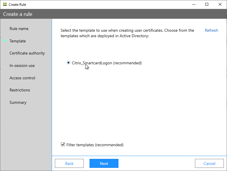
To configure a Login Schema Profile:
- Create or Edit a Login Schema .XML file based on your nFactor design.
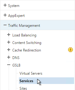
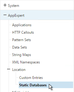
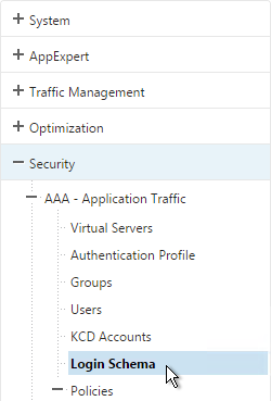
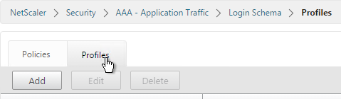
- Go to Security > AAA > Login Schema.
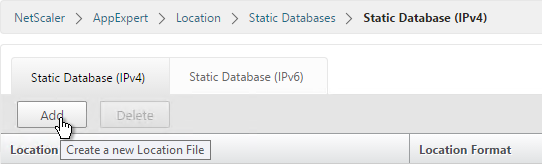
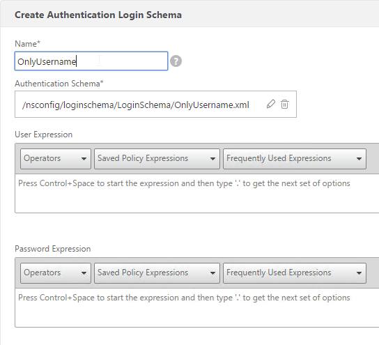
- On the right, switch to the Profiles tab and click Add.
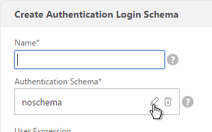
- In the Authentication Schema field, click the pencil icon.
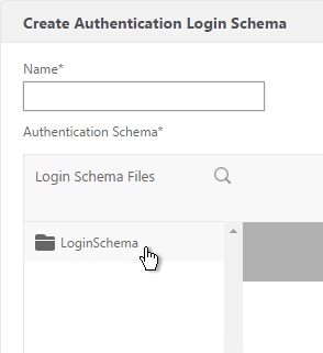
- Click the LoginSchema folder to see the files in it.
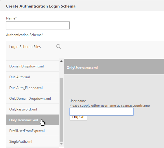
- Select one of the files. You can see a preview on the right. The labels can be changed by editing the file under /nsconfig/loginschema/LoginSchema/.
- On the top right, click Select.
- Give the Login Schema a name.
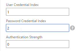
- You typically need to use the entered credentials elsewhere. For example, you might need to use the username and one of the passwords to later Single Sign-on to StoreFront. Near the bottom of the Login Schema Profile, enter unique values for the indexes. These values can be between 1 and 16.
- You can also configure these values on your noschema profiles so that passwords received from a previous factor can be put into a different Index.
- Later you reference these index values in a Traffic Policy/Profile by using the expression HTTP.REQ.USER.ATTRIBUTE(#).
- Click Create.

- Note: if you later edit the Login Schema .xml file, the changes might not be reflected until you edit the Login Schema Profile and select the .xml file again
Login Schema Policy
Login Schemas can be bound directly to a AAA Virtual Server. If one of the Advanced Authentication policies bound directly to the AAA Virtual Server is forms-based, then bind the Login Schema directly to the AAA Virtual Server. If you are binding the Login Schema directly to a AAA Virtual Server, then you must first create a Login Schema Policy expression that is linked to the Login Schema Profile.
Or Login Schemas can be bound to an Authentication Policy Label (described later). If you are binding a Login Schema to an Authentication Policy Label, then there’s no need to create a Login Schema policy expression.
To create and bind a Login Schema Policy:
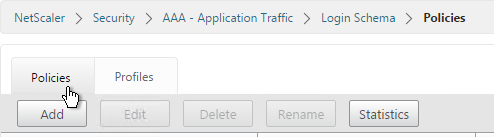
- On the left, go to Security > AAA > Login Schema.
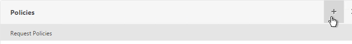
- On the right, switch to the Policies tab and click Add.
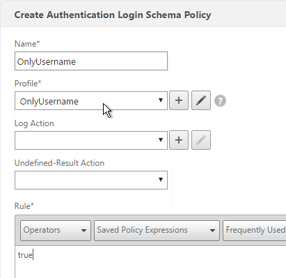
- Use the Profile drop-down to select the Login Schema Profile you already created.
- Enter a Default Syntax expression in the Rule box and click Create.
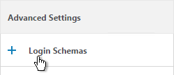
- On the left, go to Security > AAA > Virtual Servers and edit an existing AAA Virtual Server.
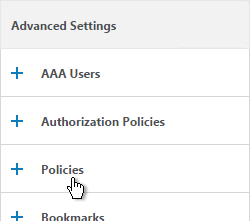
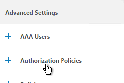
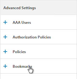
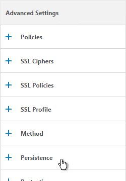
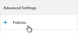
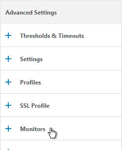
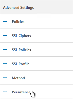
- On the right, in the Advanced Settings column, click Login Schemas.
- On the left, in the Login Schemas section, click where it says No Login Schemas.
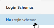
- Click to select.
- Select the Login Schema policy and click Select. Only Login Schema Policies appear in this list. Login Schema Profiles (without a policy) do not appear.
- Click Bind.
Advanced Authentication Policies
Authentication policies are a combination of policy expression and policy action. If the expression is true, then evaluate the action.
The Action is always an authentication server (LDAP, RADIUS, etc.).
The policy expression can be either in classic syntax, or in the newer default syntax.
The policy type is either Basic or Advanced. Basic policies can only use classic syntax. Advanced policies only use the newer default syntax. Both types of policies use the same Actions (authentication servers).
nFactor requires Advanced Authentication Policies; Basic policies won’t work.
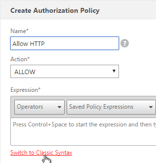
Create Advanced Authentication Policy
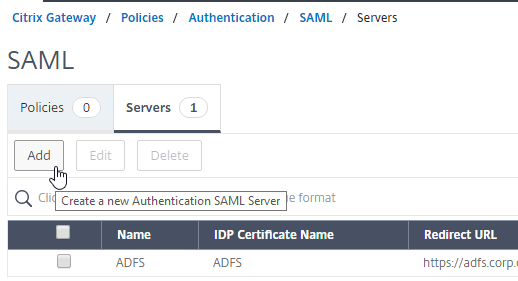
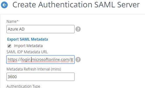
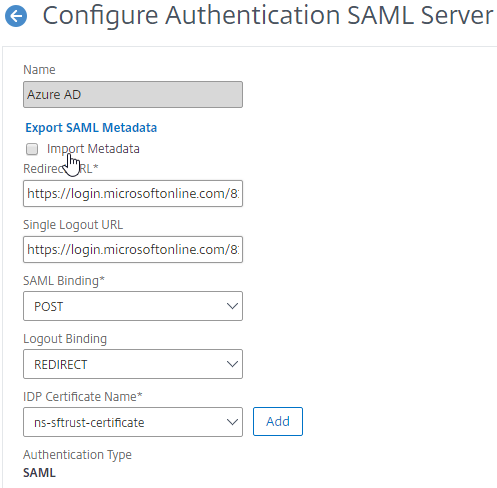
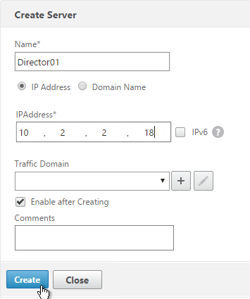
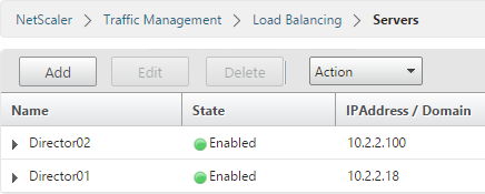
You will need Authentication Actions/Servers (e.g. LDAP, RADIUS, CERT, SAML, etc.)
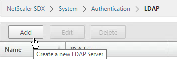
When creating an Advanced Authentication Policy, there’s a plus icon that lets you create Authentication Actions/Servers.
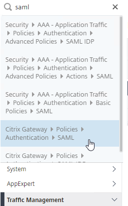
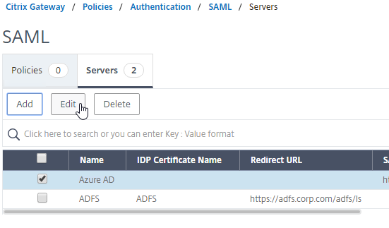
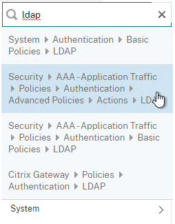
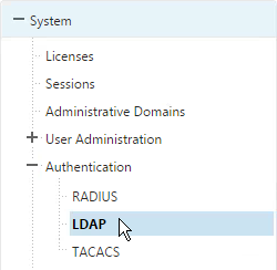
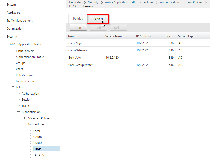
Or you can create Authentication Actions prior to creating the Advanced Authentication Policy. The Authentication Actions are located under the Security > AAA > Policies > Basic Policies > <Action Type> node. On the right, switch to the Servers tab to create the Actions/Servers. Once the Actions are created, use the instructions below to create the Advanced Authentication Policy. There’s no need to create a Basic Authentication Policy.
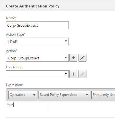
To create an Advanced Authentication Policy:
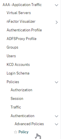
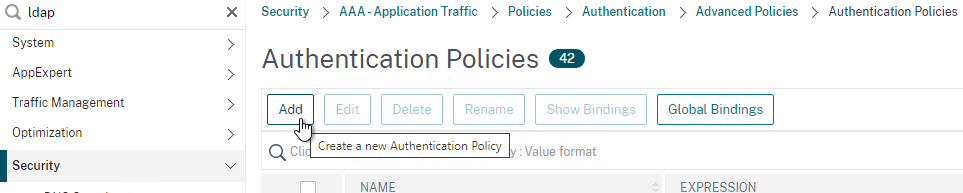
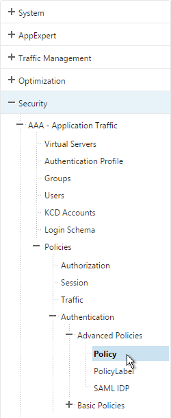
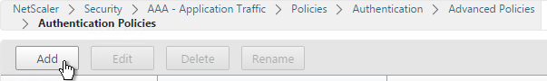
- Go to Security > AAA > Authentication > Advanced Policies > Policy.
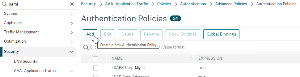
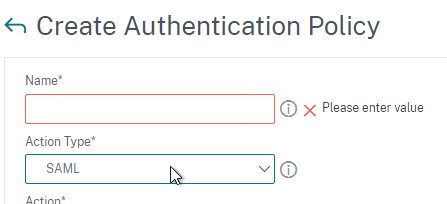
- On the right, click Add. You typically create at least one Authentication Policy for each Factor. When you create multiple Authentication Policies for one Factor, NetScaler checks each policy in priority order until one of them succeeds.
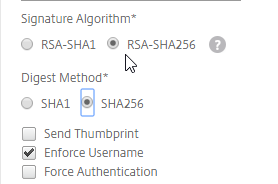
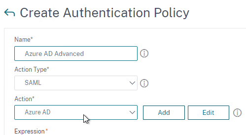
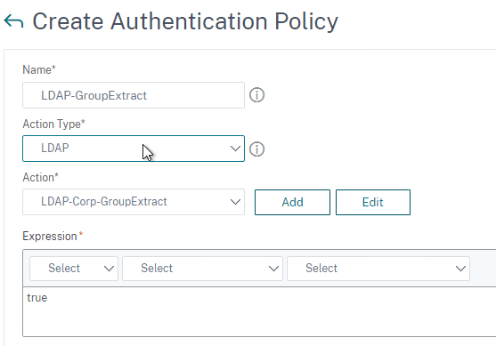
- Use the Action Type drop-down to select the Action Type (e.g. LDAP). The Action Type depends on your nFactor flow design.
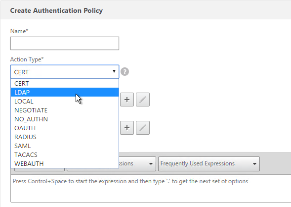
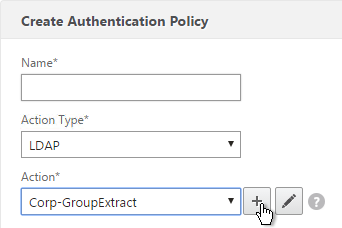
- If you don’t currently have any Actions configured, of if you want to create a new one, click the plus icon next to the Action drop-down. The Actions/Servers are created in the normal fashion.
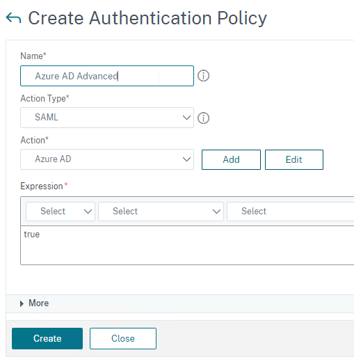
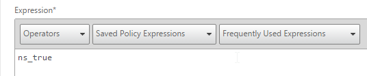
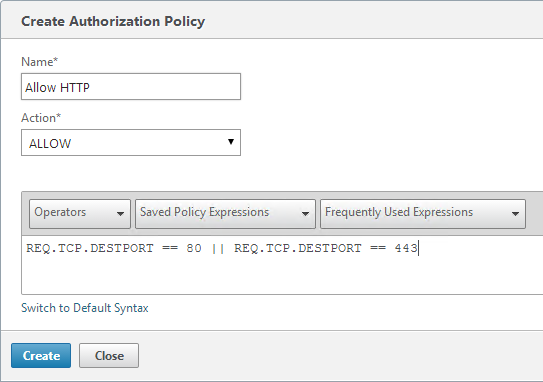
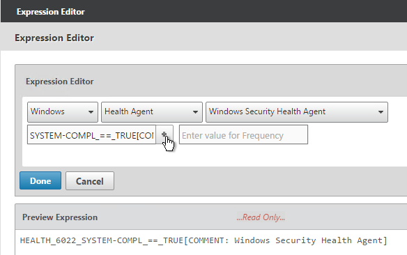
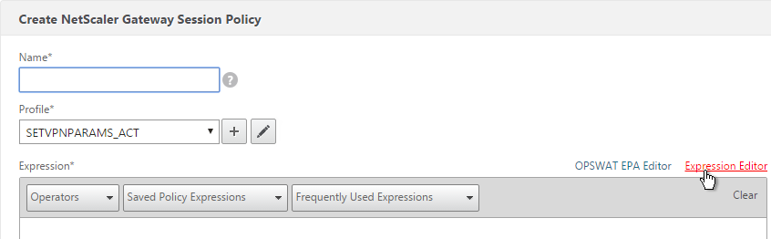
- In the Expression box, enter an expression using the Default Syntax. ns_true won’t work because that’s Classic syntax. There’s an Expression Editor link on the right. Or hit Ctrl+Space to see your options. true is a valid Default expression. Click Create when done.
- Create more Advanced Authentication Policies as needed for your nFactor design.
Bind Advanced Authentication Policy to AAA
Only the Advanced Authentication Policies for the first Factor are bound directly to the AAA Virtual Server. The Advanced Authentication Policies for the remaining Factors are bound to Authentication Policy Labels as detailed in the next section.
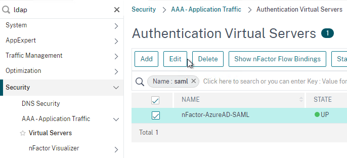
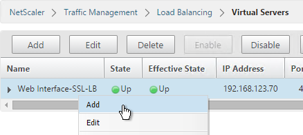
- Go to Security > AAA > Virtual Servers.
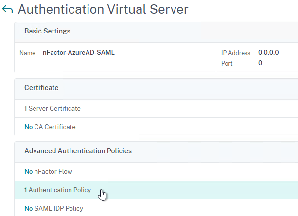
- Edit an existing AAA Virtual Server.
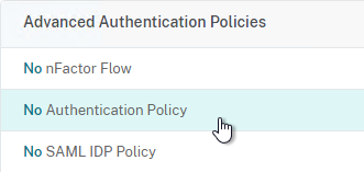
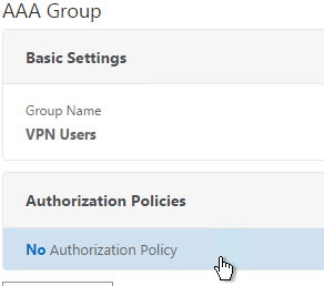
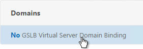
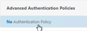
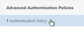
- On the left, in the Advanced Authentication Policies section, click where it says No Authentication Policy.
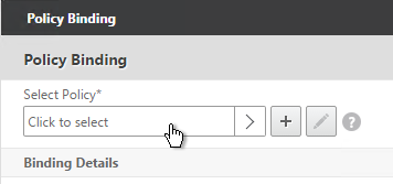
- Click to select.
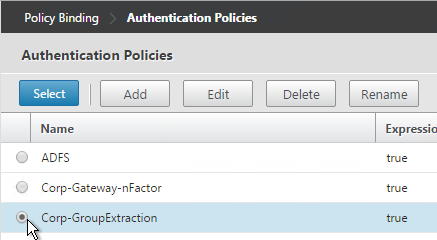
- Select the Advanced Authentication Policy and click Select.
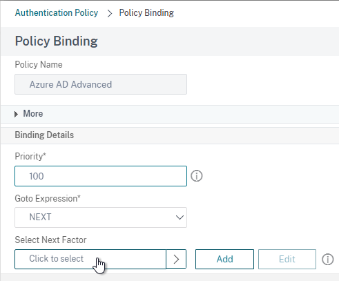
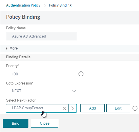
- The Select Next Factor field can optionally point to an Authentication Policy Label as detailed in the next section. The Next Factor is only evaluated if this Advanced Authentication Policy succeeds.
- If this Advanced Authentication Policy fails, then the Goto Expression determines what happens next. If it is set to NEXT, then the next Advanced Authentication Policy bound to this Factor is evaluated. If it is set to END, of if there are no more Advanced Authentication Policies bound to this Factor, then authentication is finished and marked as failed.
- Click Bind.
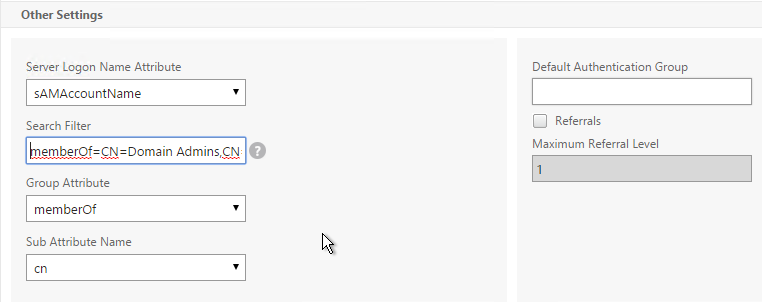
LDAP Group Extraction
Sometimes you only want to extract a user’s groups from Active Directory but have don’t actually want to authenticate with LDAP. These groups can then be used to select the next authentication Factor.
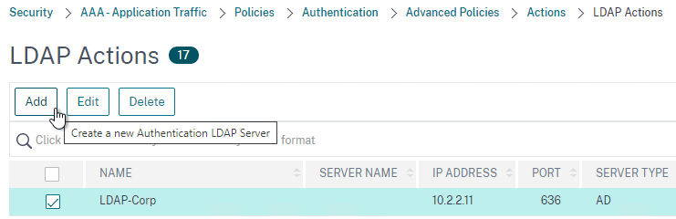
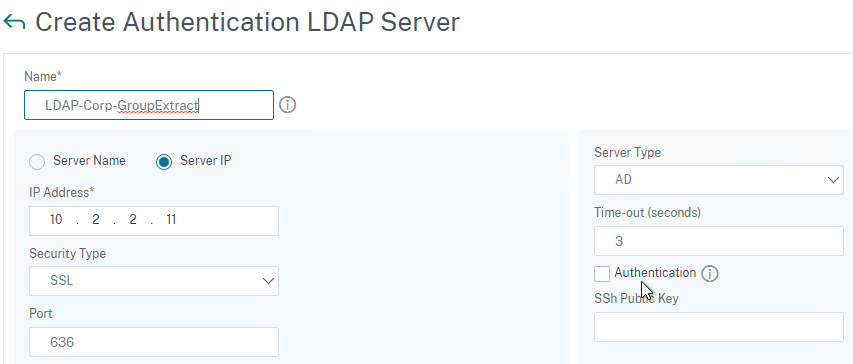
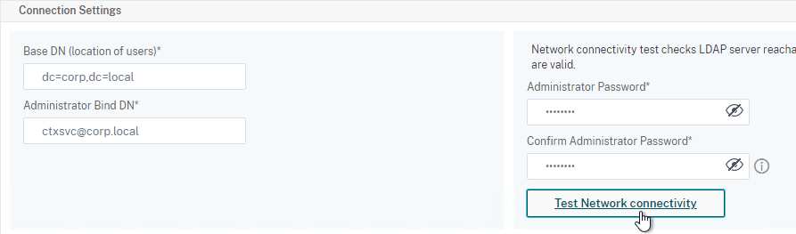
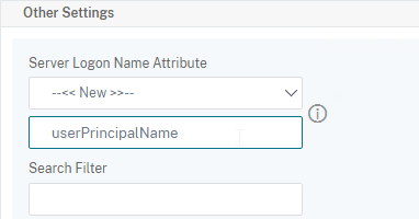
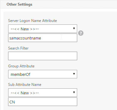
To configure an LDAP Action/Server for only group extraction:
- Make sure Authentication is unchecked.
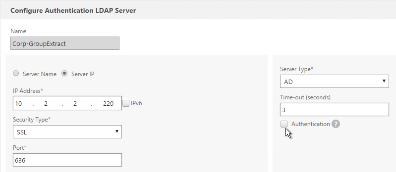
- Make sure the Group Attribute and Sub Attribute Name are filled in.
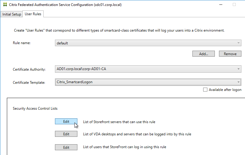
Authentication Policy Label
When configuring the first Factor, you bind two objects to the AAA Virtual Server:
- Login schema – for forms-based authentication
- Advanced Authentication Policy
When binding the Advanced Authentication Policy to the AAA Virtual Server, there’s a field to Select Next Factor. If the Advanced Authentication Policy succeeds, then the Next Factor is evaluated.
The Next Factor is actually an Authentication Policy Label.
Authentication Policy Labels contain three objects:
- Login Schema
- Advanced Authentication Policies
- Next Factor – the next Authentication Policy Label
Here’s the flow:
- User connects to AAA or NetScaler Gateway Virtual Server.
- If forms-based authentication, the Login Schema bound to the AAA Virtual Server is displayed.
- Advanced Authentication Policies bound to the AAA Virtual Server are evaluated.
- If the Advanced Authentication Policy is successful, go to the configured Next Factor, which is an Authentication Policy Label.
- If Next Factor is not configured, then authentication is complete and successful.
- If the Advanced Authentication Policy fails, and if Goto Expression is Next, then evaluate the next bound Advanced Authentication Policy.
- If none of the Advanced Authentication Policies are successful, then authentication failed.
- If the Advanced Authentication Policy is successful, go to the configured Next Factor, which is an Authentication Policy Label.
- If the Next Factor Authentication Policy Label has a Login Schema bound to it, display it to the user.
- Evaluate the Advanced Authentication Policies bound to the Next Factor Authentication Policy Label.
- If the Advanced Authentication Policy is successful, go to the configured Next Factor, which is an Authentication Policy Label.
- If Next Factor is not configured, then authentication is complete and successful.
- If the Advanced Authentication Policy fails, and if Goto Expression is Next, then evaluate the next bound Advanced Authentication Policy.
- If none of the Advanced Authentication Policies are successful, then authentication failed.
- If the Advanced Authentication Policy is successful, go to the configured Next Factor, which is an Authentication Policy Label.
- Continue evaluating the Next Factor Authentication Policy Label until authentication succeeds or fails. You can chain together an unlimited number of Authentication Policy Labels.
If you are binding a Login Schema to an Authentication Policy Label, then you only need the Login Schema Profile. There’s no need to create a Login Schema Policy.
Not every Factor needs a Login Schema (logon page). It’s possible for a prior Factor to gather all of the credential information and simply pass it on to the next Factor. If you don’t need a Login Schema for a particular Authentication Policy Label, simply select LSCHEMA_INT, which is mapped to noschema. Or create a new Login Schema Profile based on noschema.
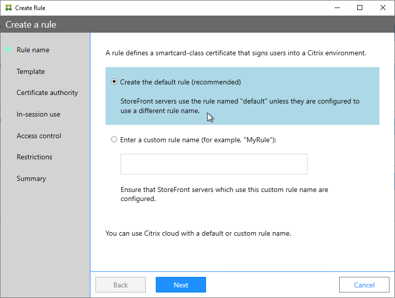
Create Authentication Policy Label
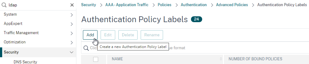
To create an Authentication Policy Label:
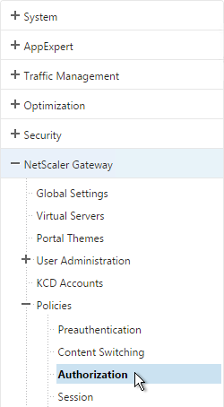
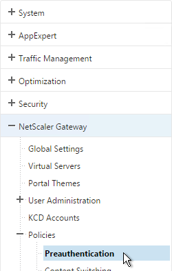
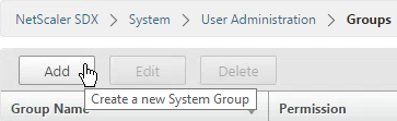
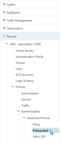
- Authentication Policy Labels are configured at Security > AAA > Policies > Authentication > Advanced Policies > PolicyLabel.
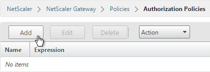
- On the right, click Add.
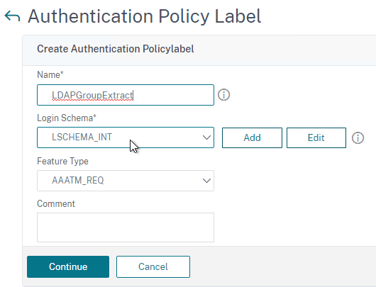
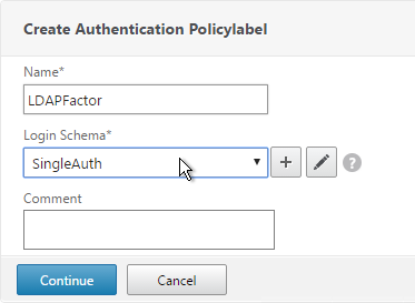
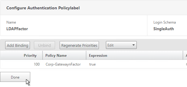
- Give the Policy Label a name.
- Select a Login Schema Profile. This can be one that is set to noschema if you don’t actually want to display anything to the user. Then click Continue.
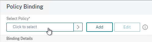
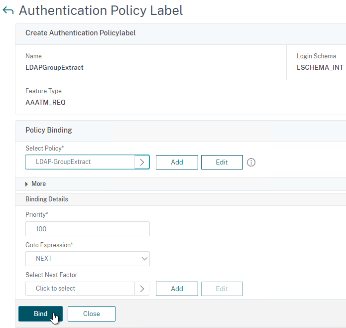
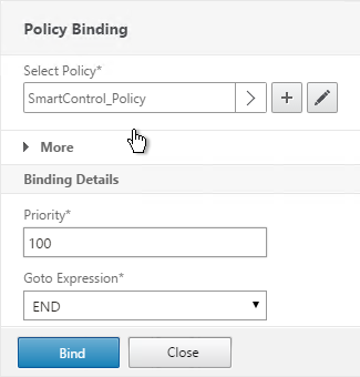
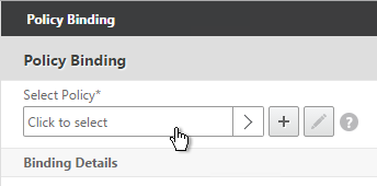
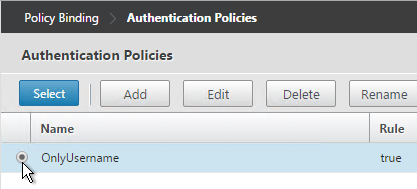
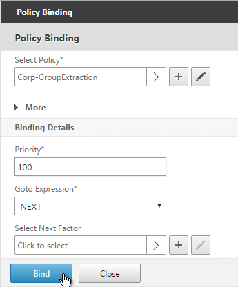
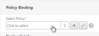
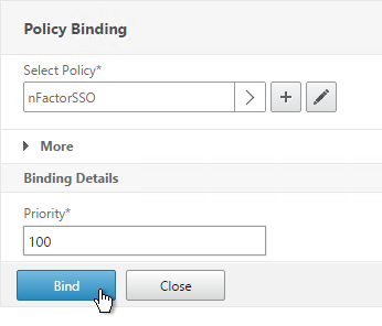
- In the Policy Binding section, Click to select.
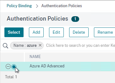
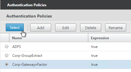
- Select an Advanced Authentication Policy that evaluates this Factor. Click Select.
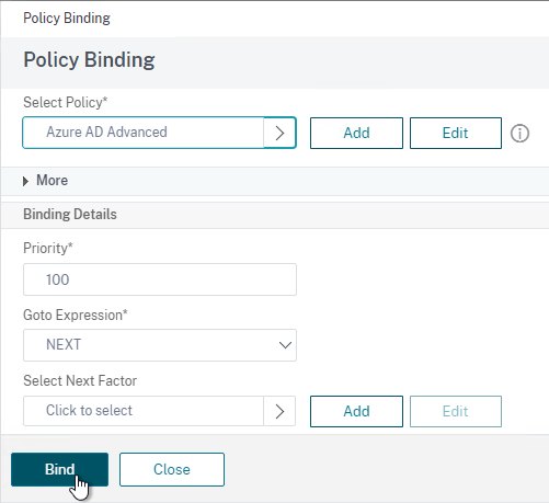
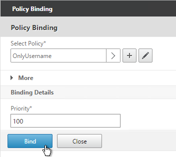
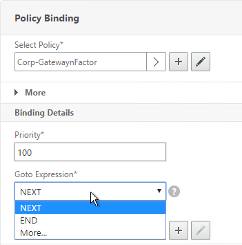
- Use the Goto Expression drop-down to select NEXT or END. If you want to bind more Advanced Authentication Policies to this Factor, then select NEXT.
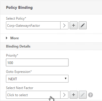
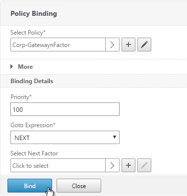
- In the Select Next Factor field, if you chain another Factor, Click to select and bind the next Authentication Policy Label (Next Factor).
- Or don’t select anything, and if this Advanced Authentication Policy succeeds, then authentication is successful and complete. This ends the chaining.
- Click Bind when done.
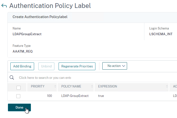
- You can click Add Binding to add more Advanced Authentication Policies to this Policy Label (Factor). Or you can bind Advanced Authentication Policies to the next Policy Label (Next Factor). Click Done.
Bind Authentication Policy Label
Once the Policy Label (Factor) is created, you bind it to an existing Advanced Authentication Policy binding. This is how you chain Factors together.
- Either edit an existing AAA Virtual Server that has an Advanced Authentication Policy already bound to it.
- Or edit a different Authentication Policy Label.
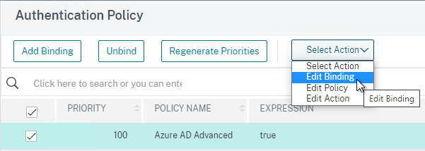
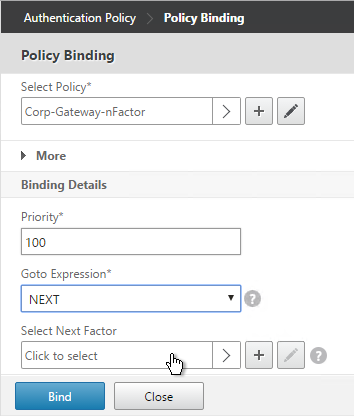
- On the left, in the Advanced Authentication Policies section, click the bindings.
- Right-click an existing binding and click Edit Binding.
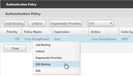
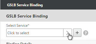
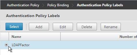
- In the Select Next Factor field, Click to select.
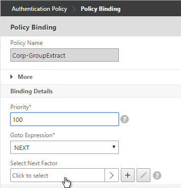
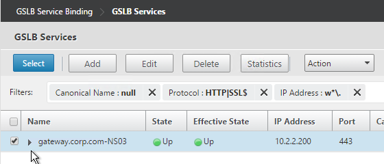
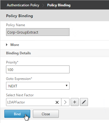
- Select the Policy Label for the Next Factor and click Select.
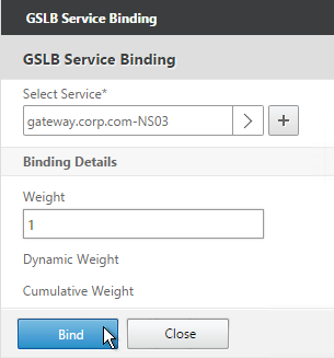
- Click Bind.
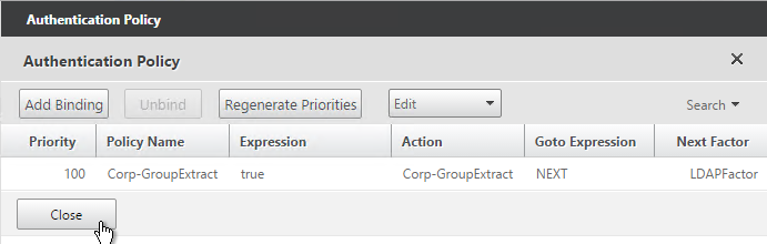
- Click Done.
nFactor for NetScaler Gateway
AAA Authentication Profile
Authentication Profile lets you bind a AAA Virtual Server to NetScaler Gateway. This is what enables nFactor on NetScaler Gateway.
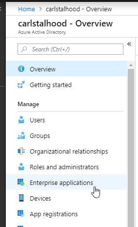
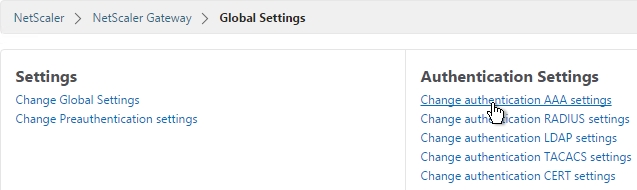
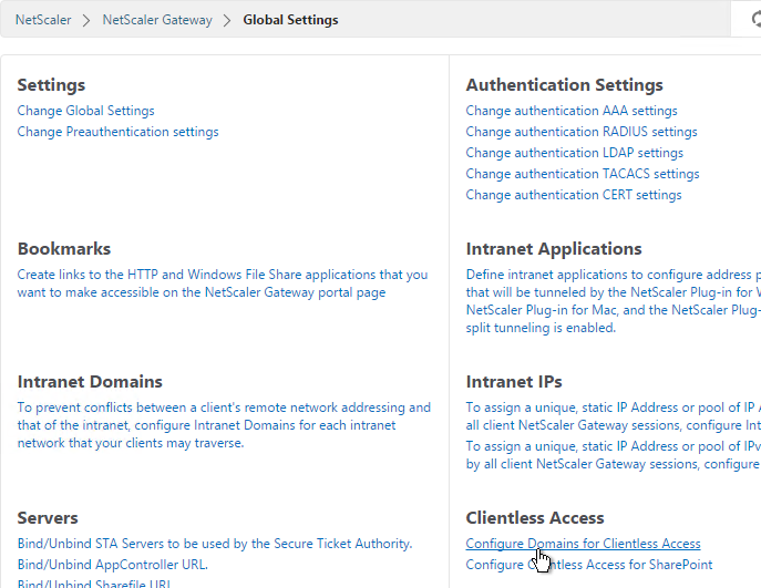
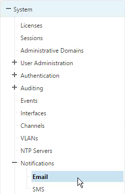
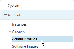
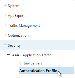
- Go to Security > AAA > Authentication Profile.
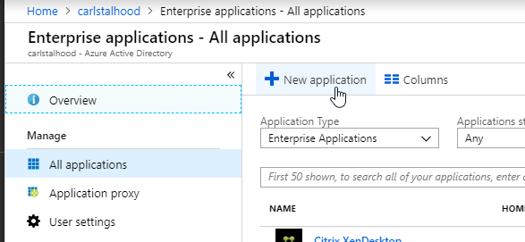
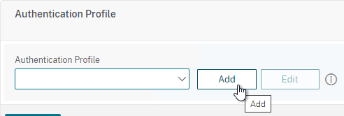
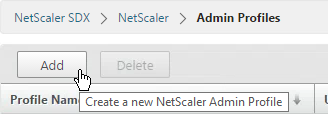
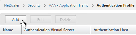
- On the right, click Add.
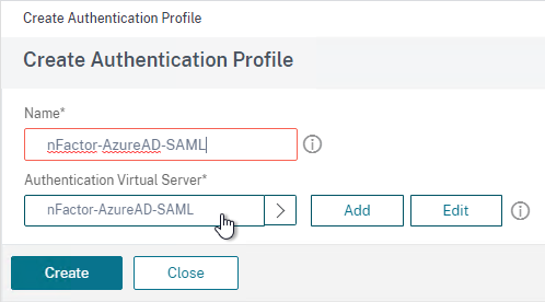
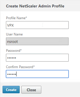
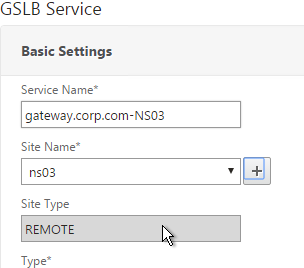
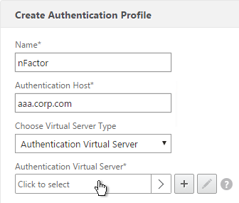
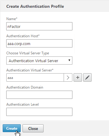
- Give the Authentication Profile a name.
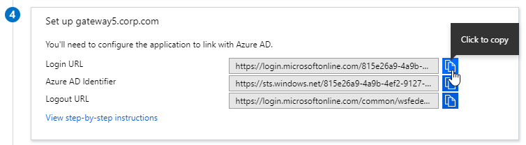
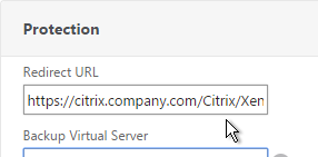
- In the Authentication Host field, it wants a URL to redirect users to your AAA Virtual Server. If you do this configuration from the CLI then this field is optional. But in the GUI it is required. NetScaler Gateway does not need to redirect so it doesn’t matter what you enter here.
- In the Authentication Virtual Server field, Click to select.
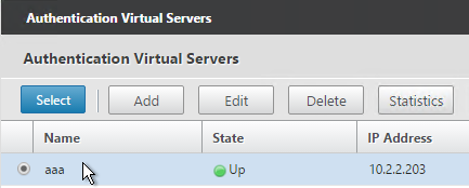
- Select the AAA Virtual Server that has Login Schema, Advanced Authentication Policy, and Authentication Policy Labels configured. The AAA Virtual Server does not need an IP address. Click Select.
- Then click Create.
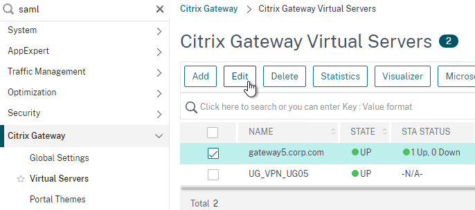
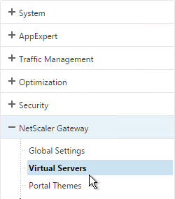
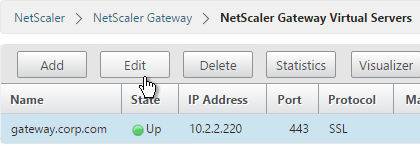
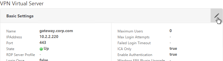
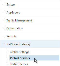
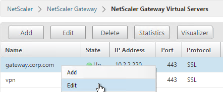
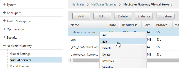
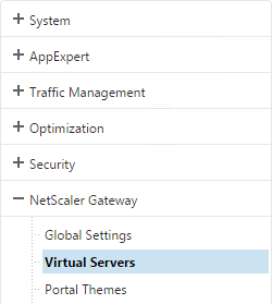
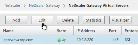
- Go to NetScaler Gateway > Virtual Servers.
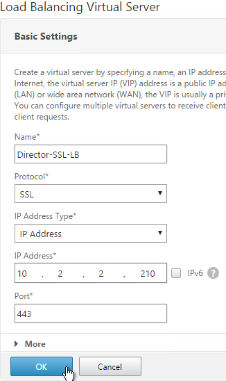
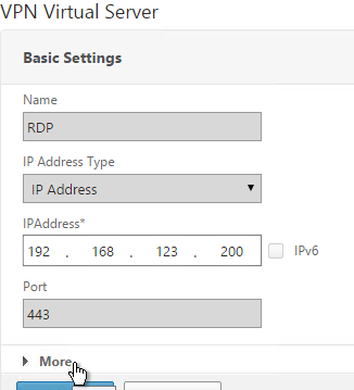
- On the right, edit an existing Gateway Virtual Server.
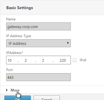
- In the Basic Settings section, click the pencil icon.
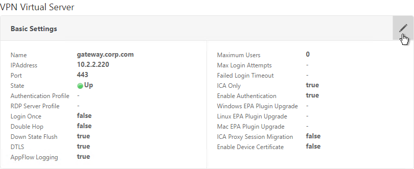
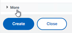
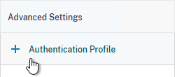
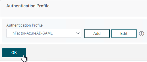
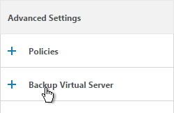
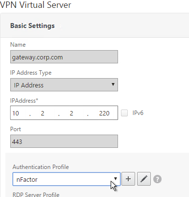
- Click More.
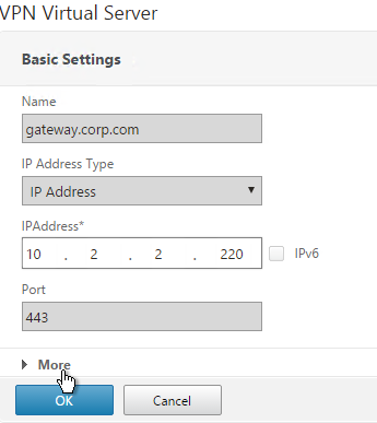
- Use the Authentication Profile drop-down to select the Authentication Profile you just created.
- If one of your Factors is client certificates, then you’ll need to configure SSL Parameters and CA certificate as detailed in the next section.
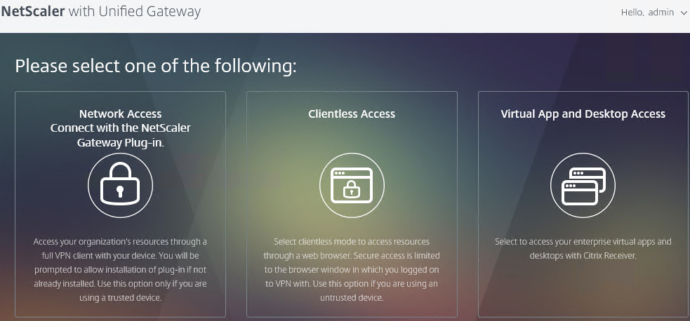
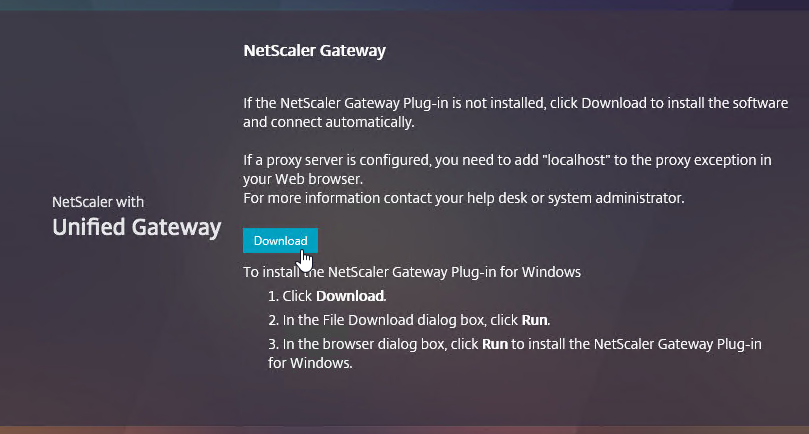
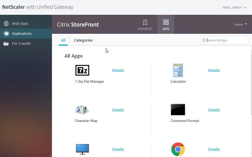
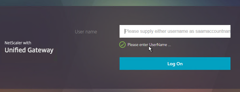
- When you browse to your Gateway, you’ll see the nFactor authentication screens.
Gateway Client Certificate Authentication
If one of your authentication Factors is certificate, then you must perform some SSL configuration on the NetScaler Gateway Virtual Server:
- Go to Traffic Management > SSL > Certificates and install the root certificate for the issuer of the client certificates. Certificate Authority certificates do not need key files.
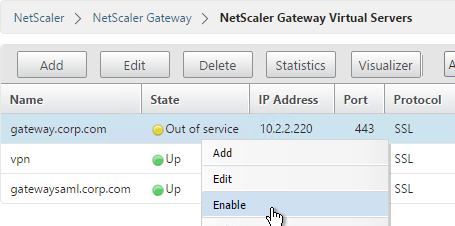
- Go to NetScaler Gateway > Virtual Servers, and edit an existing NetScaler Gateway Virtual Server that is enabled for nFactor.
- On the left, in the SSL Parameters section, click the pencil icon.
- Check the box next to Client Authentication.
- Make sure Client Certificate drop-down is set to Optional, and click OK.
- On the left, in the Certificates section, click where it says No CA Certificate.
- Click to select.
- Select the root certificate for the issuer of the client certificates and click Select.
- Click Bind.
nFactor Single Sign-on to StoreFront
When performing Single Sign-on to StoreFront, nFactor defaults to using the last entered password. If LDAP is not the last entered password, then you need to create a Traffic Policy/Profile to override the default nFactor behavior.
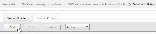
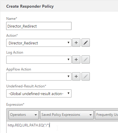
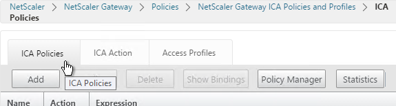
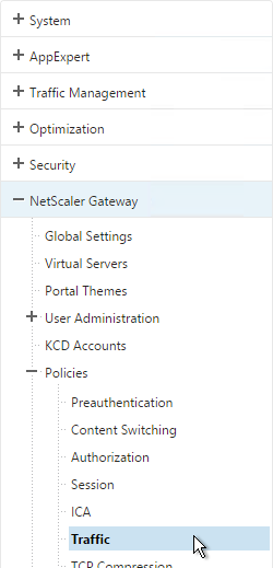
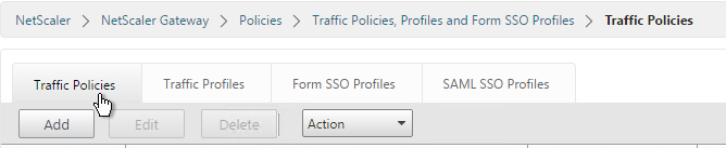
- Go to NetScaler Gateway > Policies > Traffic.
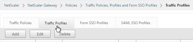
- On the right, switch to the Traffic Profiles tab.
- Click Add.
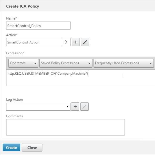
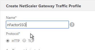
- Give the Traffic Profile a name.
- In the Protocol section, select HTTP. Scroll down.
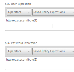
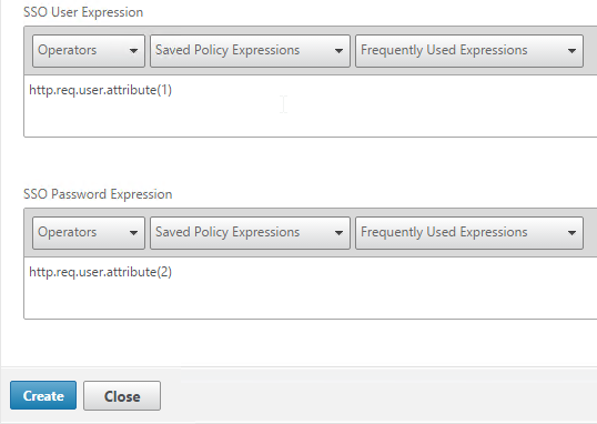
- In the SSO Expression fields, enter an HTTP.REQ.USER.ATTRIBUTE(#) expression that matches the indexes specified in the Login Schema.
- Click Create.
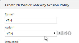
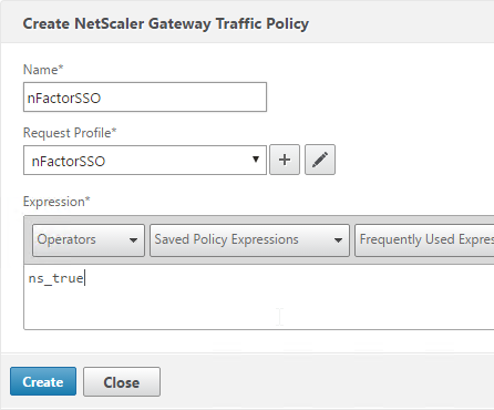
- On the right, switch to the Traffic Policies tab and click Add.
- Give the policy a name.
- Select the previously created Traffic Profile.
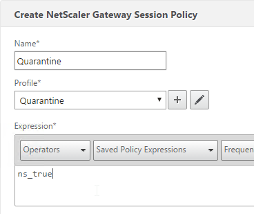
- Enter a classic expression (e.g. ns_true) and click Create.
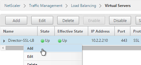
- Edit an existing NetScaler Gateway Virtual Server.
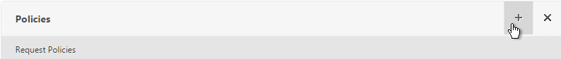
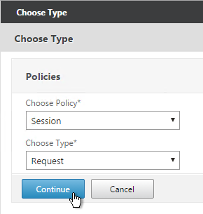
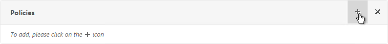
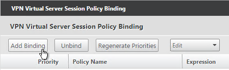
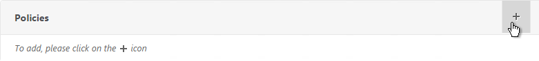
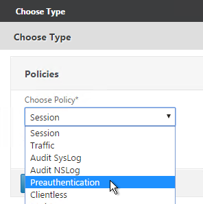
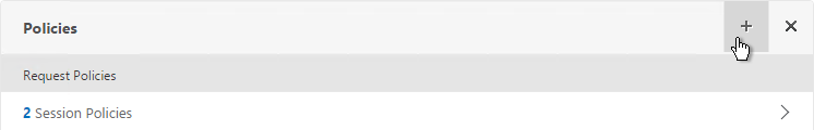
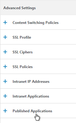
- Scroll down to the Policies section and click the plus icon.
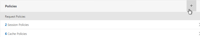
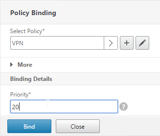
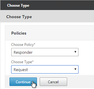
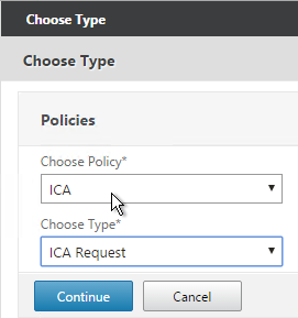
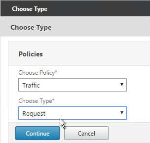
- Select Traffic > Request and click Continue.
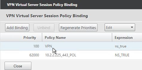
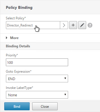
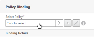
- Select the previously created Traffic Policy.
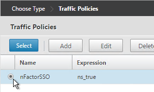
- Bind the Traffic Policy.
Sample Configurations
From Citrix Docs: Sample deployments using nFactor authentication:
- Getting two passwords up-front, pass-through in next factor. Read
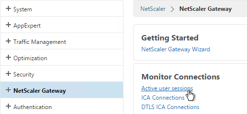
- Group extraction followed by certificate or LDAP authentication, based on group membership. Read
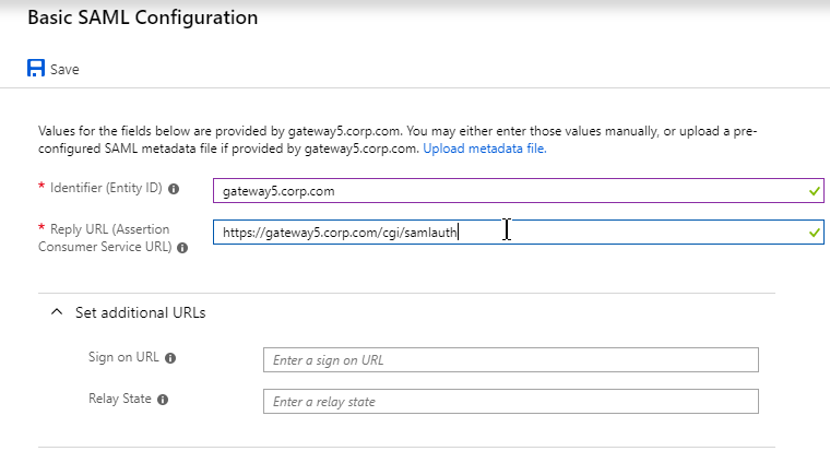
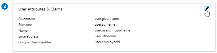
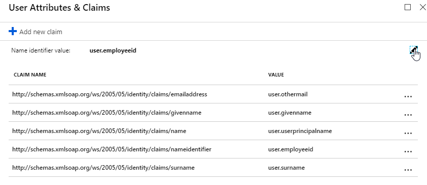
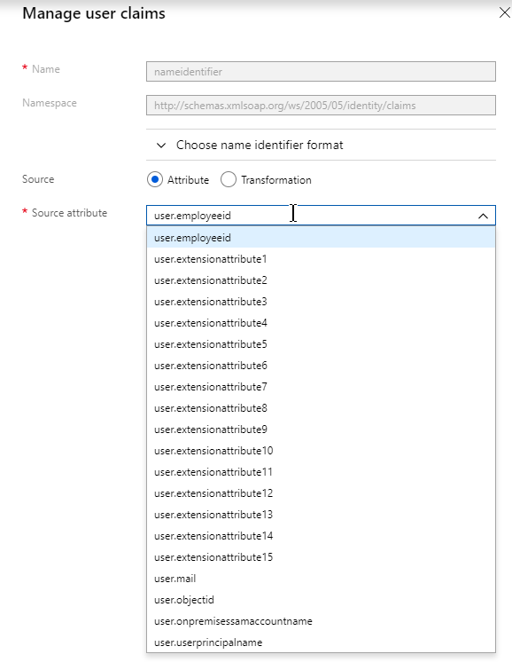
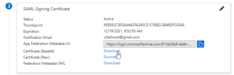
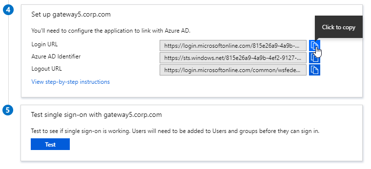
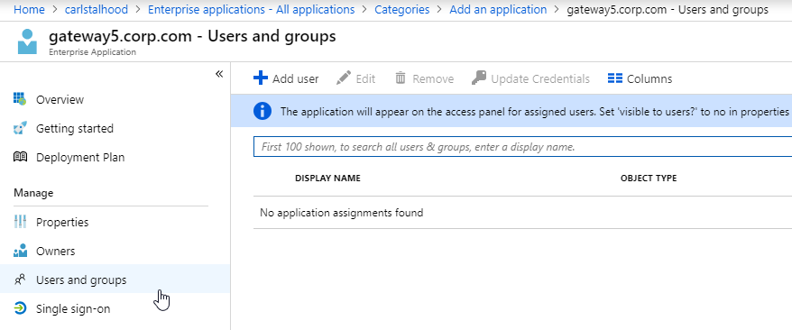
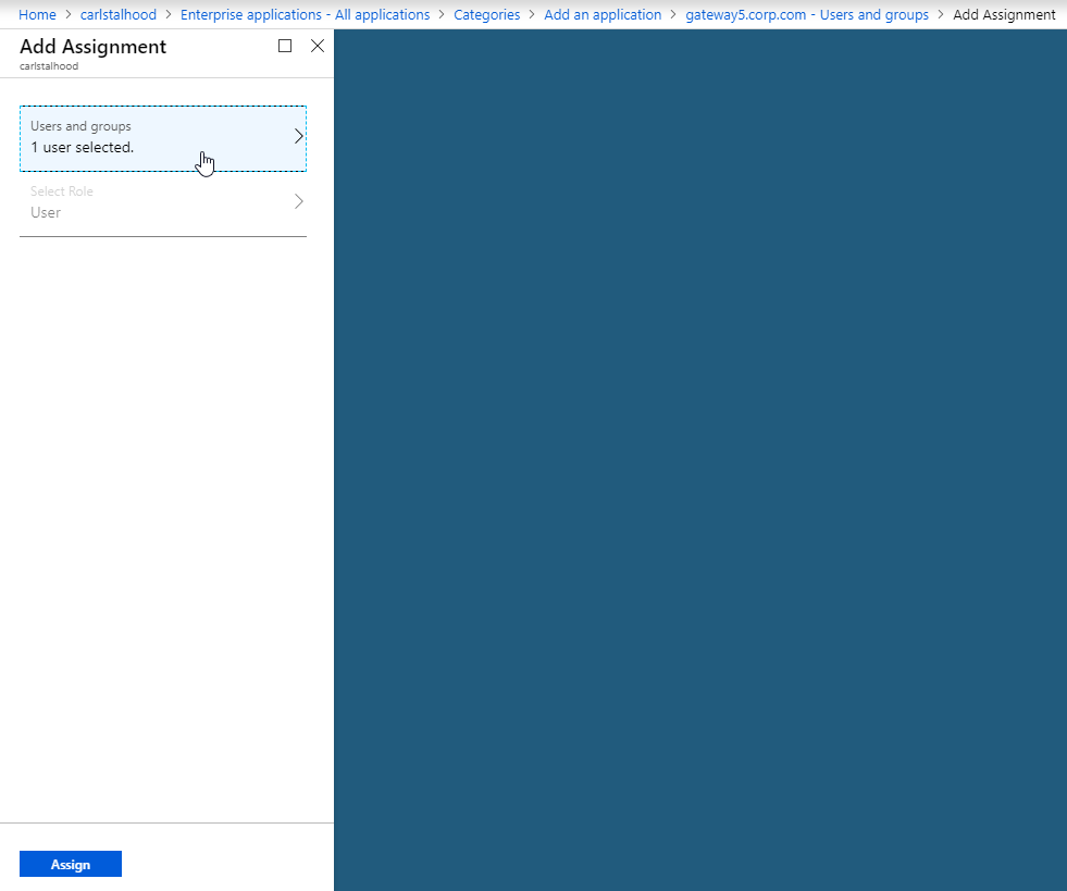
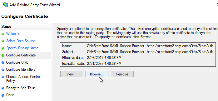
- SAML followed by LDAP or certificate authentication, based on attributes extracted during SAML.Read
- SAML in first factor, followed by group extraction, and then LDAP or certificate authentication, based on groups extracted. Read
- Prefilling user name from certificate. Read
- Certificate authentication followed by group extraction for 401 enabled traffic management virtual servers. Read
- Username and 2 passwords with group extraction in third factor.Read
- Certificate fallback to LDAP in same cascade; one virtual server for both certificate and LDAP authentication. Read
- LDAP in first factor and WebAuth in second factor.Read
- Domain drop down in first factor, then different policy evaluations based on group.Read
Certificate auth: If Successful, LDAP only. If Failure, LDAP+RADIUS
This scenario is described in Citrix Blog Post Configuration Notes on nFactor
The authentication process flows like this:
- User connects to NetScaler Gateway.
- NetScaler Gateway asks user for certificate.
- If user selects a certificate, NetScaler Gateway compares certificate signature to the CA certificate that is bound to the NetScaler Gateway. If it doesn’t match, then user certificate is ignored.
- Bound to the NetScaler Gateway Virtual Server is an Authentication Profile, which links NetScaler Gateway to AAA nFactor.
- Certificate authentication: The lowest priority number authentication policy on the AAA Virtual Server is Certificate. If there’s a valid user certificate:
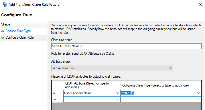
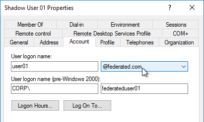
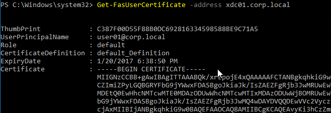
- Extract the user’s userPrincipalName from the certificate.
- Next Factor = policy label that displays a logon screen (Single-factor Login Schema)
- The username field is pre-populated with the userPrincipalName attribute extracted from the certificate.
- User is prompted to enter the LDAP password only.
- LDAP policy/server is configured to use userPrincipalName to login to LDAP.
- If successful, NetScaler Gateway authentication is complete. Next step is to Single Sign-on to StoreFront.
- If LDAP authentication fails, then NetScaler Gateway authentication fails, and the user is prompted to try LDAP-only authentication again.
- LDAP authentication: If certificate authentication fails, try next authentication policy bound to the AAA Virtual Server, which is a different LDAP Policy.
- Bound to the AAA Virtual Server is a Dual Factor Login Schema that asks for username, LDAP password, and RADIUS password.
- LDAP policy/server is configured to use sAMAccountName to login to LDAP. SAMAccountName means users don’t have to enter full userPrincipalName.
- If LDAP authentication is successful:
- Put username in Credential Index 1 and put password in Credential Index 2. These will later be used by a Traffic Policy to Single Sign-on to StoreFront.
- Proceed to next factor (Policy Label), which is RADIUS.
- If LDAP authentication fails, NetScaler Gateway login fails, and the user is prompted to try two-factor authentication again.
- RADIUS authentication: the second factor Policy Label is configured with Noschema. This means no additional logon form is displayed because the RADIUS password was already collected in the previous factor.
- When multiple passwords are collected, they are tried in order. The first password was used by the previous factor. The second password is tried by this factor (Policy Label).
- RADIUS policy/profile attempts authentication.
- If RADIUS authentication is successful, NetScaler Gateway authentication is complete. Next step is Single Sign-on to StoreFront.
- If RADIUS authentication fails, NetScaler Gateway login fails, and the user is prompted to try two-factor authentication again.
- Single Sign-on to StoreFront: NetScaler Gateway uses the last password collected by nFactor to Single Sign-on with StoreFront. If the last password is LDAP, then no additional configuration is needed. If the last password is not LDAP, then a Traffic Policy/Profile is needed.
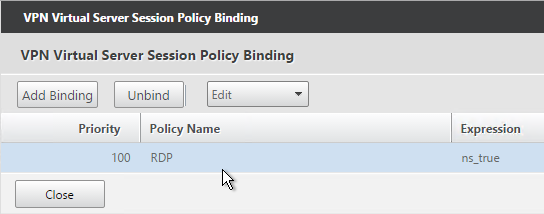
- Bound to the NetScaler Gateway Virtual Server is a Traffic Policy.
- The Traffic Policy/Profile users Credential Index 1 for username and Credential Index 2 for Password. These are the same indexes configured in the Dual Factor Login Schema.
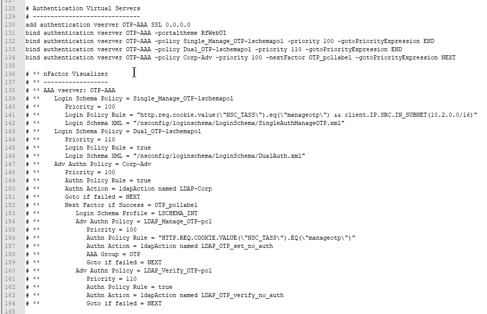
The order of configuration doesn’t match the authentication flow because some objects have to be created before others.
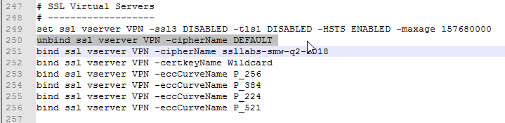
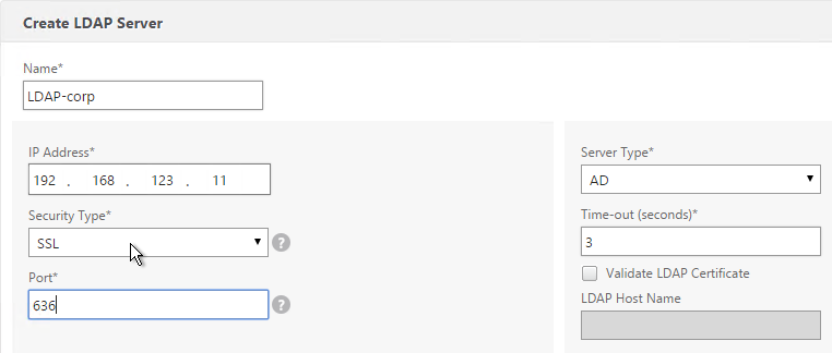
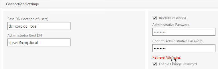
# Create Auth vServer, bind server cert, bind CA cert for client certificates
# Enable Optional client certificates
add authentication vserver nFactorAAA SSL 0.0.0.0 443 -AuthenticationDomain corp.com
bind ssl vserver nFactorAAA -certkeyName WildCorpCom
bind ssl vserver nFactorAAA -certkeyName CorpRoot -CA -ocspCheck Optional
set ssl vserver nFactorAAA -clientAuth ENABLED -clientCert Optional -ssl3 DISABLED

# Create auth policy for LDAP-UPN
add authentication ldapAction Corp-UserPrincipalName -serverIP 10.2.2.220 -serverPort 636 -ldapBase "dc=corp,dc=local" -ldapBindDn "corp\\ctxsvc" -ldapBindDnPassword "MyPassword" -ldapLoginName userPrincipalName -groupAttrName memberOf -subAttributeName CN -secType SSL -passwdChange ENABLED
add authentication Policy Corp-UserPrincipalName -rule true -action Corp-UserPrincipalName

# Create PolicyLabel LDAPPasswordOnly with Single-factor Login Schema
add authentication loginSchema SingleAuth -authenticationSchema "/nsconfig/loginschema/LoginSchema/SingleAuth-Corp.xml"
add authentication policylabel LDAPPasswordOnly -loginSchema SingleAuth
bind authentication policylabel LDAPPasswordOnly -policyName Corp-UserPrincipalName -priority 100 -gotoPriorityExpression NEXT

# Create Cert policy and bind to AAA vServer with LDAPPasswordOnly PolicyLabel as Next Factor
# Cert policy must have lower priority number than LDAP-SAM policy
add authentication certAction Cert_Auth_Profile -userNameField SubjectAltName:PrincipalName
add authentication Policy Cert_Auth_Policy -rule true -action Cert_Auth_Profile
bind authentication vserver nFactorAAA -policy Cert_Auth_Policy -priority 100 -nextFactor LDAPPasswordOnly -gotoPriorityExpression NEXT

# Create LDAP-SAM Auth Policy
add authentication ldapAction Corp-Gateway -serverIP 10.2.2.220 -serverPort 636 -ldapBase "dc=corp,dc=local" -ldapBindDn "corp\\ctxsvc" -ldapBindDnPassword "MyPassword" -ldapLoginName samaccountname -groupAttrName memberOf -subAttributeName CN -secType SSL -passwdChange ENABLED
add authentication Policy Corp-SAMAccountName -rule true -action Corp-Gateway

# Create RADIUS Auth Policy
add authentication radiusAction RADIUS-Action -serverIP 10.2.2.42 -serverPort 1812 -radKey MyKey
add authentication Policy RADIUS-Policy -rule true -action RADIUS-Action

# Create Dual-factor Login Schema and bind directly to AAA vServer
# This Login Schema is only shown if Cert auth fails
add authentication loginSchema DualAuth -authenticationSchema "/nsconfig/loginschema/LoginSchema/DualAuth.xml" -userCredentialIndex 1 -passwordCredentialIndex 2
add authentication loginSchemaPolicy DualAuth -rule true -action DualAuth
bind authentication vserver nFactorAAA -policy DualAuth -priority 100 -gotoPriorityExpression END

# Create RADIUS Policy Label with noschema and RADIUS Auth Policy
add authentication loginSchema Noschema -authenticationSchema noschema
add authentication policylabel NoSchema-RADIUS -loginSchema Noschema
bind authentication policylabel NoSchema-RADIUS -policyName RADIUS-Policy -priority 100 -gotoPriorityExpression NEXT

# Bind LDAP-SAM Auth Policy to AAA vServer with RADIUS as next factor
# LDAP-SAM Auth Policy must have higher priority number than Cert Policy
bind authentication vserver nFactorAAA -policy Corp-SAMAccountName -priority 110 -nextFactor NoSchema-RADIUS -gotoPriorityExpression NEXT

# Create Authentication Profile to link AAA with Gateway. Bind to Gateway.
add authentication authnProfile nFactor -authnVsName nFactorAAA -AuthenticationHost aaa.corp.com
add vpn vserver gateway.corp.com SSL 10.2.2.220 443 -icaOnly ON -dtls ON -Listenpolicy NONE -tcpProfileName nstcp_default_XA_XD_profile -appflowLog ENABLED -authnProfile nFactor

# Enable Optional Client certs on Gateway
set ssl vserver gateway.corp.com -clientAuth ENABLED -clientCert Optional -ssl3 DISABLED
bind ssl vserver gateway.corp.com -certkeyName CorpRoot -CA -ocspCheck Optional

# Create Traffic Policy to SSON to StoreFront. Bind to Gateway.
add vpn trafficAction nFactorSSO http -kcdAccount NONE -userExpression "http.req.user.attribute(1)" -passwdExpression "http.req.user.attribute(2)"
add vpn trafficPolicy nFactorSSO ns_true nFactorSSO
bind vpn vserver gateway.corp.com -policy nFactorSSO -priority 100