NetScaler Gateway 11.1 – LDAP Authentication

Last Modified: Nov 7, 2020 @ 6:34 am

Navigation

💡 = Recently Updated

LDAP Load Balancing

Before you create an LDAP authentication policy, load balance the Domain Controllers. If you don’t load balance your Domain Controllers, then when users enter an incorrect password, the user account will be prematurely locked out.

If you have multiple domains, create different Load Balancing Virtual Servers for each domain. These multiple Load Balancing Virtual Servers can share the same VIP if their port numbers are different. Or you can use a different VIP for each domain.

LDAP Authentication Server

To create the LDAP Authentication Server, do the following:

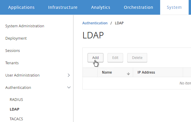
  1. On the left, expand Authentication and click Dashboard.
  2. On the right, click Add.
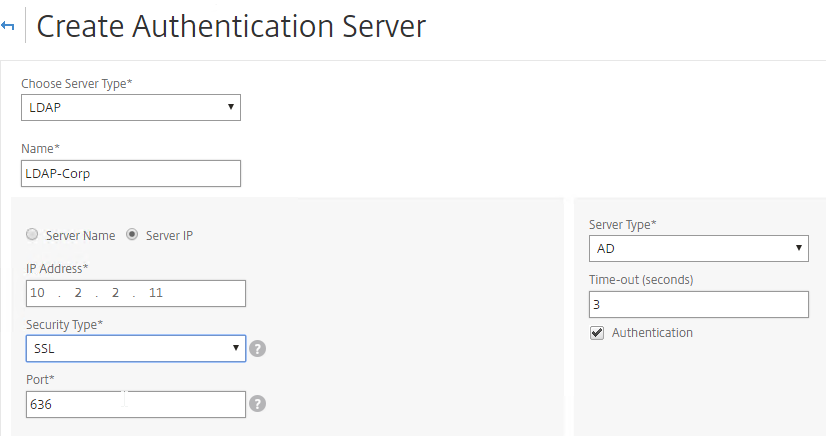
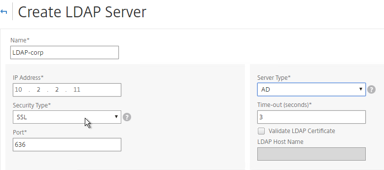
  3. In the Choose Server Type drop-down, select LDAP.
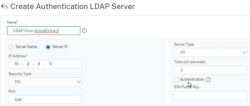
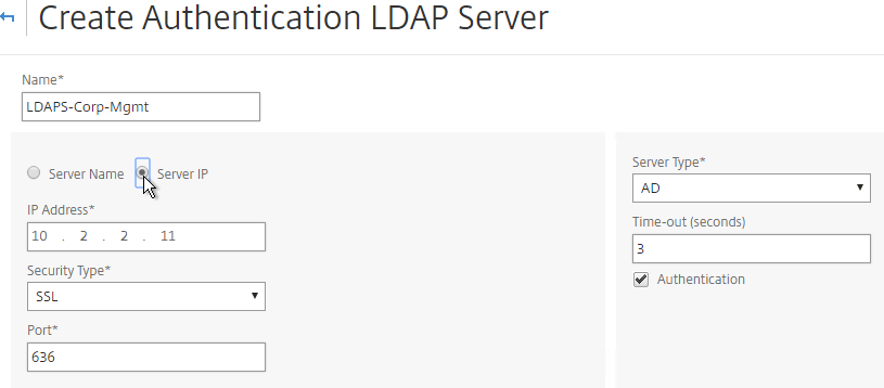
  4. Enter LDAP-Corp as the name. If you have multiple domains, you’ll need a separate LDAP Server per domain so make sure you include the domain name.
  5. Change the selection to Server IP. Enter the VIP of the load balancing vServer for LDAP.
  6. Change the Security Type to SSL.
  7. Enter 636 as the Port. Scroll down.
  8. Note: it’s also possible to point the LDAP Server IP to a Global Catalog. See Citrix CTX200506 How to Change Password through NetScaler in a Multi-Domain Active Directory Forest Using LDAP Referral for configuration details.  💡
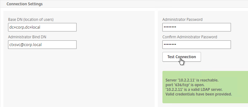
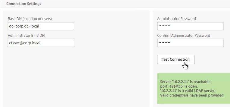
  9. In the Connection Settings section, in the Base DN field, enter your Active Directory DNS domain name in LDAP format.
  10. In the Administrator Bind DN field, enter the credentials of the LDAP bind account in userPrincipalName format. Domain\Username also works.
  11. Enter the Administrator password.
  12. Click Test Connection. NetScaler will attempt to login to the LDAP IP. Scroll down.
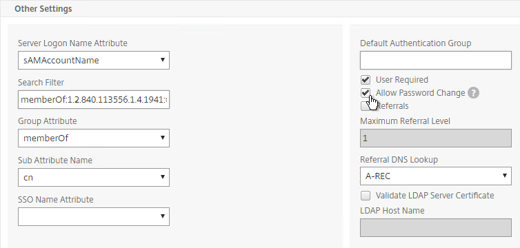
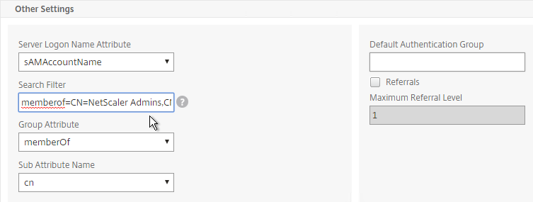
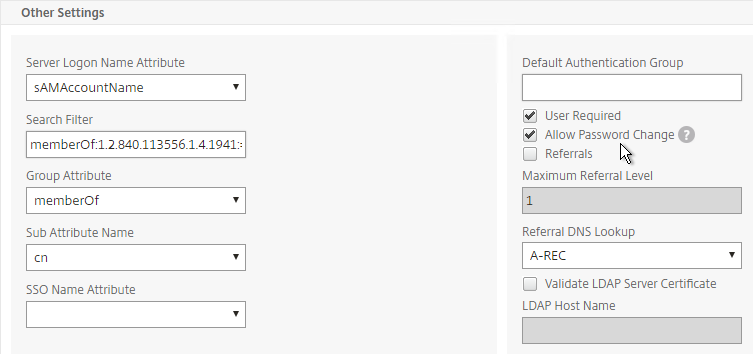
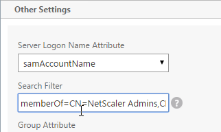
  13. In the Other Settings section, use the drop-down next to Server Logon Name Attribute, Group Attribute, and Sub Attribute Name to select the default fields for Active Directory.
  14. On the right, check the box next to Allow Password Change.
  15. Note: there is a checkbox for Validate LDAP Server Certificate. If you want to do this, see Citrix Discussions for instructions for loading the root certificate to /nsconfig/truststore.
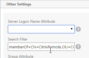
  16. If you want to restrict access to only members of a specific group, in the Search Filter field, enter memberOf=<GroupDN>. See the example below:
    memberOf=CN=CitrixRemote,OU=Citrix,DC=corp,DC=local
    You can add :1.2.840.113556.1.4.1941: to the query so it searches through nested groups. Without this users will need to be direct members of the filtered group.
    memberOf:1.2.840.113556.1.4.1941:=CN=CitrixRemote,OU=Citrix,DC=corp,DC=local

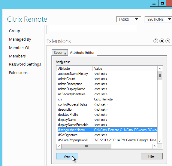
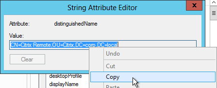
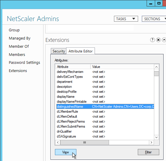
    1. An easy way to get the full distinguished name of the group is through Active Directory Administrative Center. Double-click the group object and switch to the Extensions page. On the right, switch to the Attribute Editor tab.
    2. Or in Active Directory Users & Computers, enable Advanced view, browse to the object (don’t use Find), double-click the object, and switch to the Attribute Editor tab.
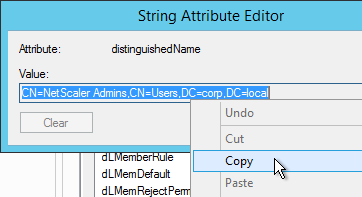
    3. Scroll down to distinguishedName, double-click it and then copy it to the clipboard.

    4. Back on the NetScaler, in the Search Filter field, type in memberOf= and then paste the Distinguished Name right after the equals sign. Don’t worry about spaces.
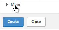
  17. Scroll down and click More.
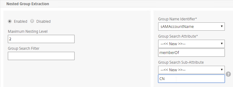
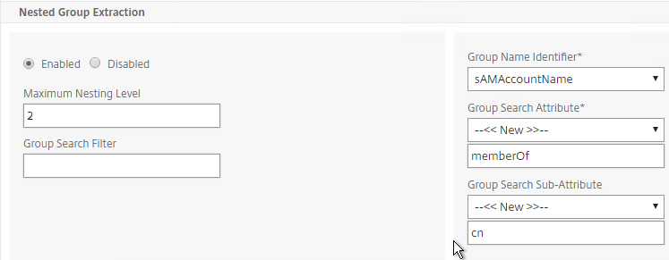
  18. For Nested Group Extraction, if desired, change the selection to Enabled.
  19. Set Group Name Identifier to samAccountName.
  20. Set Group Search Attribute to memberOf. Select << New >> first.
  21. Set Group Search Sub-Attribute to CN. Select << New >> first.
  22. For the Group Search Filter field, see CTX123795 Example of LDAP Nested Group Search Filter Syntax.
  23. Scroll down and click Create.

    add authentication ldapAction Corp-Gateway -serverIP 10.2.2.210 -serverPort 636 -ldapBase "dc=corp,dc=local" -ldapBindDn "corp\\ctxsvc" -ldapBindDnPassword Passw0rd -ldapLoginName samaccountname -searchFilter "memberOf=CN=Citrix Remote,CN=Users,DC=corp,DC=local" -groupAttrName memberOf -subAttributeName CN -secType SSL -passwdChange ENABLED
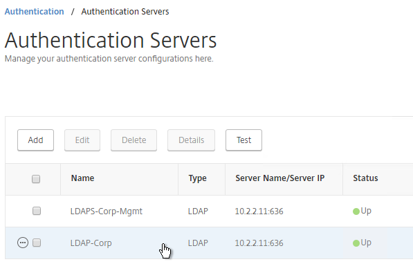
  24. The status of the LDAP Server should be Up.

LDAP Policy Expression

The Authentication Dashboard doesn’t allow you to create the LDAP Policy so you must create it elsewhere.

You can create the LDAP policy now. Or you can wait and create it later when you bind the LDAP Server to the NetScaler Gateway vServer.

To create it now:

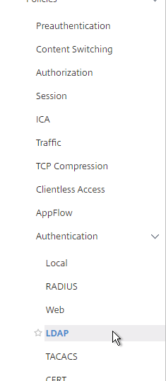
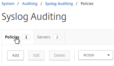
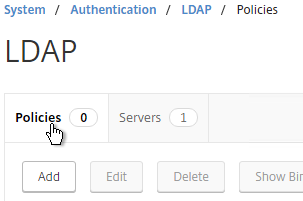
  1. Go to NetScaler Gateway > Policies > Authentication > LDAP.
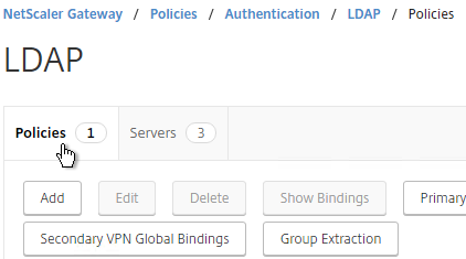
  2. On the right, in the Policies tab, click Add.
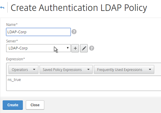
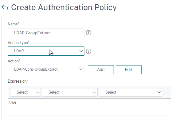
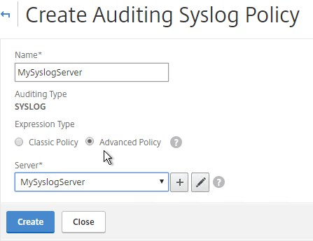
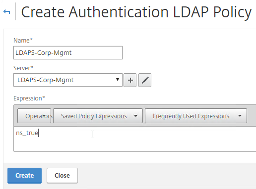
  3. Change the Server drop-down to the LDAP Server you created earlier.
  4. Give the LDAP Policy a name (one for each domain).
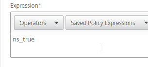
  5. In the Expression box, enter ns_true.
  6. Click Create.

     add authentication ldapPolicy LDAP-Corp ns_true LDAP-Corp

Gateway Authentication Feedback and Licenses

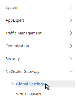
  1. On the left, under NetScaler Gateway, click Global Settings.
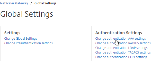
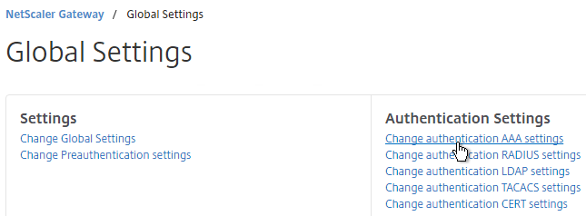
  2. On the right, in the right column, click Change authentication AAA settings.
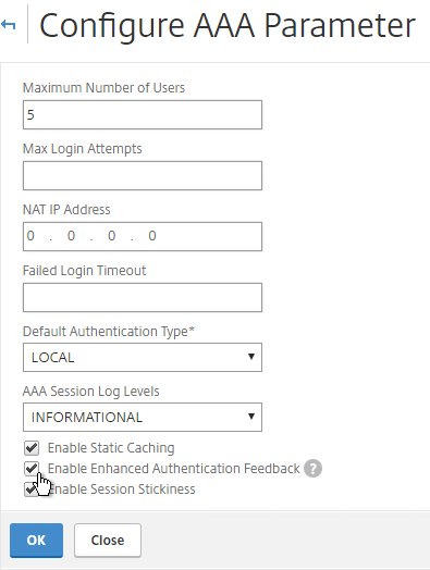
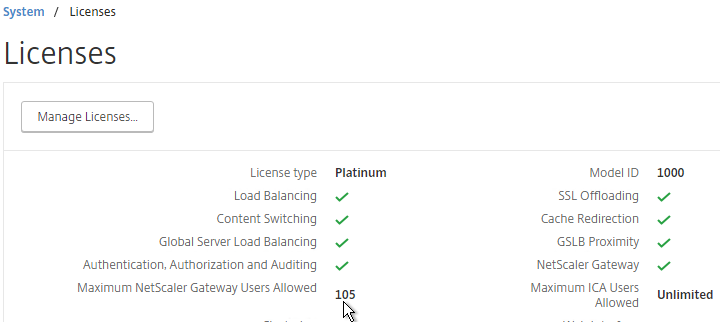
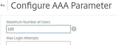
  3. If you are using Gateway features that require Gateway Universal licenses, then change the Maximum Number of Users to the number of Gateway Universal licenses you have installed on this appliance. This field has a default value of 5, and administrators frequently forget to change it, thus only allowing 5 users to connect.
  4. If desired, check the box for Enable Enhanced Authentication Feedback. This feature provides a message to users if authentication fails. The message users receive include password errors, account disabled or locked, or the user is not found, to name a few. Click OK.

    set aaa parameter -enableEnhancedAuthFeedback YES -maxAAAUsers 200

Next Step

Multiple Domains – UPN Method

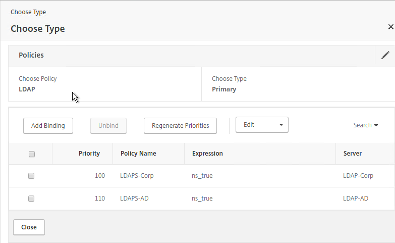
To support multiple Active Directory domains on a NetScaler Gateway, you create multiple LDAP authentication policies, one for each Active Directory domain, and bind all of the LDAP policies to the NetScaler Gateway Virtual Server. When the user logs into NetScaler Gateway, only the username and password are entered. The NetScaler will then loop through each of the LDAP policies in priority order until it finds one that contains the entered username/password.

What if the same username is present in multiple domains? As NetScaler loops through the LDAP policies, as soon as it finds one with the specified username, it will try to authenticate with that particular LDAP policy. If the password doesn’t match the user account for the attempted domain then a failed logon attempt will be logged in that domain and NetScaler will try the next domain.

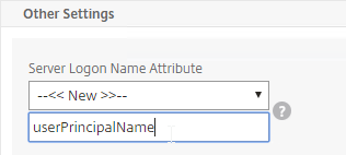
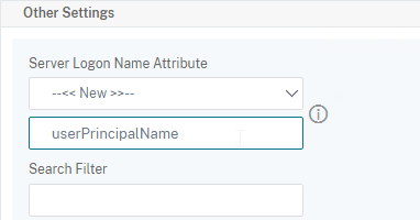
Unfortunately, the only way to enter a realm/domain name during user authentication is to require users to login using userPrincipalNames. To use userPrincipalName, set the LDAP Policy/Server with the Server Logon Name Attribute set to userPrincipalName.

You can even do a combination of policies: some with samAccountName and some with userPrincipalName. The samAccountName policies would be searched in priority order and the userPrincipalName policies can be used to override the search order. Bind the userPrincipalName policies higher (lower priority number) than the samAccountName policies.

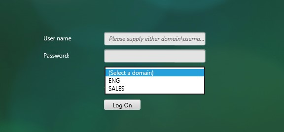
NetScaler 11.1 supports adding a domain name drop-down list to the logon page. Then use Cookie expressions in the auth policies and session policies. However, this probably doesn’t work for Receivers. See CTX203873 How to Add Drop-Down Menu with Domain Names on Logon Page for NetScaler Gateway 11.0 64.x and later releases for details.
User-added image

Another option for a domain drop-down is nFactor Authentication for Gateway. This also doesn’t work with Receiver Self-service.

After authentication is complete, a Session Policy will be applied that has the StoreFront URL. The NetScaler Gateway will attempt to log into StoreFront using Single Sign-on so the user doesn’t have to login again. When logging into NetScaler Gateway, only two fields are required: username and password. However, when logging in to StoreFront, a third field is required: domain name. So how does NetScaler specify the domain name while logging in to StoreFront?

There are two methods of specifying the domain:

  • AAA Group – Configure multiple session policies with unique Single Sign-on Domains.  Inside the Session Policy is a field called Single Sign-on Domain for specifying the domain name. If there is only one Active Directory domain, then you can use the same Session Policy for all users. However, if there are multiple domains, then you would need multiple Session Policies, one for each Active Directory domain. But as the NetScaler loops through the LDAP policies during authentication, once a successful LDAP policy is found, you need a method of linking an LDAP policy with a Session Policy that has the corresponding SSO Domain. This is typically done using AAA groups. To use this method, see Multiple Domains – AAA Group Method.
  • userPrincipalName – Alternatively, configure the LDAP policy/server to extract the user’s UPN, and then authenticate to StoreFront using UPN. This is the easiest method but some domains don’t have userPrincipalNames configured correctly.

The userPrincipalName method is detailed below:

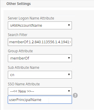
  1. In each of your NetScaler LDAP policies/servers, in the Other Settings section, in the SSO Name Attribute field, enter userPrincipalName (select –<< New >>– first). Make sure there are no spaces after this attribute name. NetScaler will use this pull this attribute from AD, and use it to Single Sign-on the user to StoreFront.
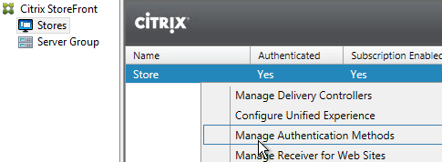
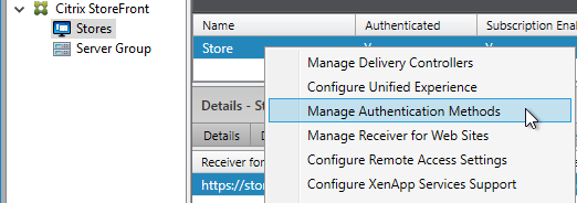
  2. In StoreFront Console, right-click  the Store, and click Manage Authentication Methods.
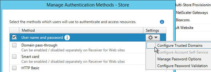
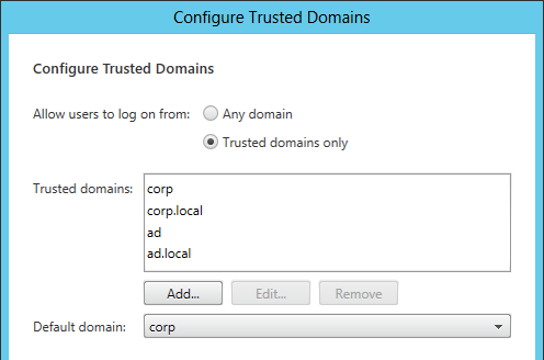
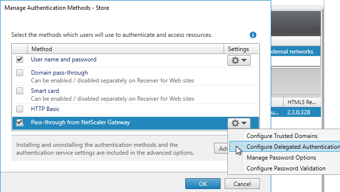
  3. On the right, click the gear icon, and then click Configure Trusted Domains.
  4. In the Trusted domains box, select Any domain.
  5. Or add your domains in DNS format. The advantage of entering domain names is that you can select a default domain if internal users forget to enter a domain name during login. The DNS format is required for UPN logins (e.g. SSO from NetScaler Gateway).
  6. On the NetScaler Gateway Virtual Server, bind LDAP authentication polices in priority order. It will search them in order until it finds a match.
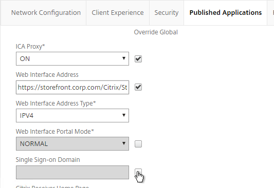
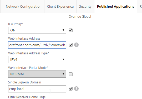
  7. In your Session Policies/Profiles, in the Published Applications tab, make sure Single Sign-on Domain is not configured. Since NetScaler is using the userPrincipalName there’s no need to specify a domain. If Single Sign-on Domain is configured then Single Sign-on authentication will fail.

Multiple Domains – AAA Groups Method

Another method of specifying the domain name when performing Single Sign-on to StoreFront is to use a unique session policy/profile for each domain. Use AAA Groups to distinguish one domain from another.

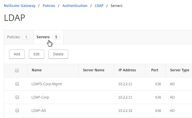
  1. Go to NetScaler Gateway > Policies > Authentication > LDAP.
  2. On the right, switch to the Servers tab. Make sure all domains are in the list. Edit one of the domains.
  3. Scroll down to the Other Settings section,
  4. In the Default Authentication Group field, enter a new, unique group name. Each domain has a different group name. Click OK.
  5. Edit another domain and specify a new unique group name. Each domain has a different group name.
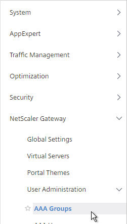
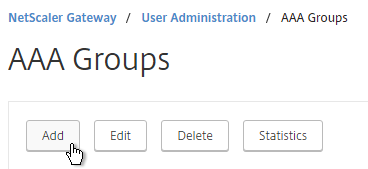
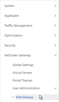
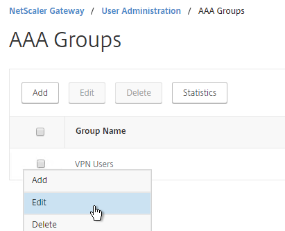
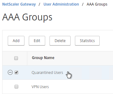
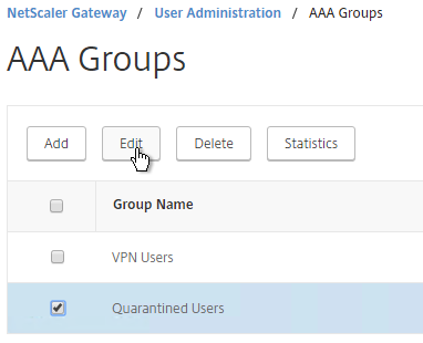
  6. Go to NetScaler Gateway > User Administration > AAA Groups.
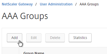
  7. On the right, click Add.
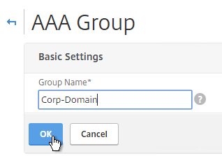
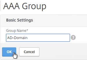
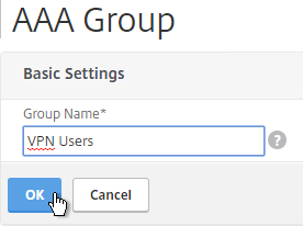
  8. Name the group so it exactly matches the group name you specified in the LDAP server. Click OK.
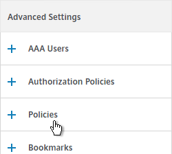
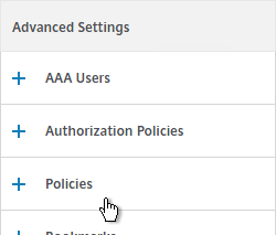
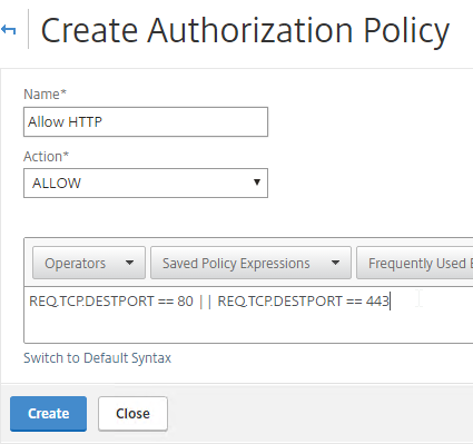
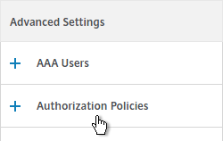
  9. On the right, in the Advanced Policies section, add the Policies section.
  10. On the left, in the Policies section, click the Plus icon.
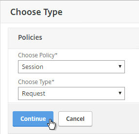
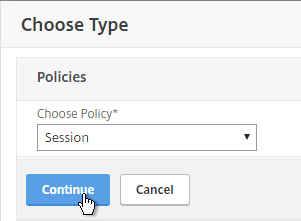
  11. Select Session, and click Continue.
  12. Click the plus icon to create a new policy.
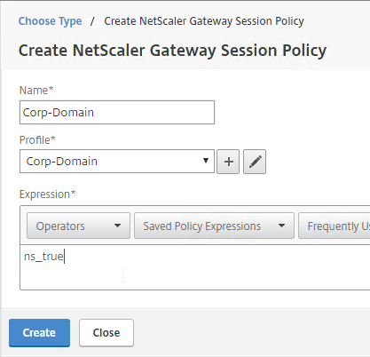
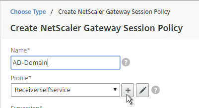
  13. Give it a name that indicates the domain. You will have a separate policy for each domain.
  14. Click the plus icon to create a new profile.
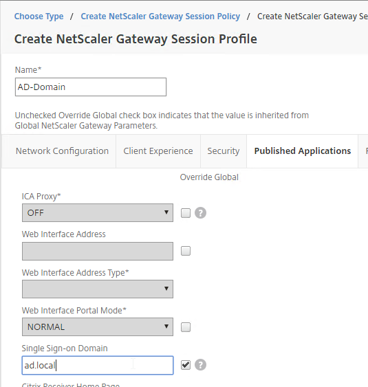
  15. Give the Profile a name that indicates the domain. You will have a separate profile for each domain.
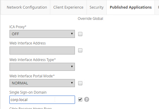
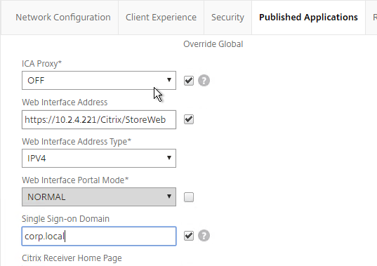
  16. Switch to the Published Applications tab.
  17. Check the Override Global box next to Single Sign-on Domain. Enter the domain name that StoreFront is expecting. Click Create.
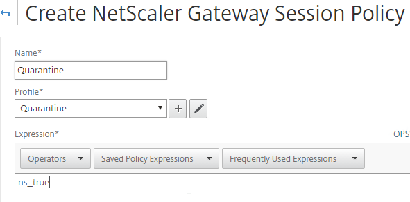
  18. Give the policy a ns_true expression, and click Create.
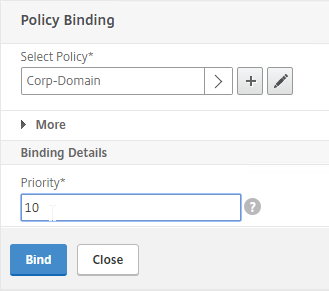
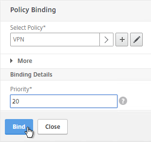
  19. In the Priority field, give it a number that is lower than any other Session Policy that has Single Sign-on Domain configured. Click OK.
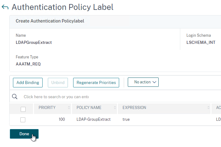
  20. Click Done.
  21. Create another AAA Group.
  22. Give it a name for the next domain.
  23. Create another Session Policy for the next domain.
  24. Create another profile for the next domain. On the Published Applications tab, specify the domain name of the next domain.
  25. Bind the new policy with a low Priority number.
  26. When a user logs in, NetScaler loops through LDAP policies until one of them works. NetScaler adds the user to the Default Authentication Group specified in the LDAP Server. NetScaler finds a matching AAA Group and applies the Session Policy that has SSON Domain configured. Since the policy is bound with a low priority number, it overrides any other policy that also has SSON Domain configured.

Domain Controller (LDAPS) Load Balancing – NetScaler 11.1

Last Modified: Nov 6, 2020 @ 7:26 am

Navigation

Overview

If you plan to use LDAP (Active Directory) for NetScaler Gateway or NetScaler management authentication, load balance the Domain Controllers that are used for authentication.

An alternative to load balancing is to configure NetScaler Gateway and NetScaler management authentication with multiple authentication policies, each pointing to a single Domain Controller. However, NetScaler will try each authentication policy until it finds one that works. If the user enters a wrong password and if you have three authentication policies pointing to different Domain Controllers in the same domain then three different failure attempts will be recorded thus causing premature account lockout. Use Load Balancing to avoid this behavior.

This page details LDAPS, aka Secure LDAP. This protocol requires certificates to be installed on the Domain Controllers. When a user’s password expires, Active Directory does not allow password changes over clear text LDAP so LDAPS must be used instead. Make sure you have certificates installed on your Domain Controllers. The easiest way to accomplish that is to deploy a Microsoft Certificate Authority. Once that’s done the Domain Controllers will request certificates automatically.

An ldaps monitor can be used to verify that the Domain Controller is functional. The ldaps monitor will login as an account, perform an LDAP query, and look for a successful response. The ldaps monitor uses a service account to login. Make sure the service account’s password does not expire. Domain User permissions are sufficient. Since this monitor is a Perl script, it uses NSIP as the source IP. You can use RNAT to override this as described in CTX217712 How to Force scriptable monitor to use SNIP in Netscaler in 10.5.

If you have Domain Controllers in multiple datacenters, you can create multiple load balancing Virtual Servers and cascade them so that the local Domain Controllers are used first, and if they’re not available, then the Virtual Server fails over to Domain Controllers in remote datacenters.

The Load Balancing Virtual Server for LDAPS can be TCP or SSL_TCP:

  • If the protocol is TCP, then SSL-encrypted LDAP traffic is not terminated on the NetScaler, and is simply forwarded to the LDAP servers. If your LDAP client needs to verify the LDAP server certificate, then this Load Balancing configuration will not work, since each back-end LDAP server will have a different certificate.
  • If your Load Balancing Virtual Server is protocol SSL_TCP, then a certificate must be installed on the NetScaler and bound to the Load Balancing Virtual Server. SSL is terminated at the NetScaler and re-encrypted before sending it to the destination Domain Controller. The primary benefit of NetScaler SSL termination is that your LDAP clients can verify the Virtual Server SSL certificate.

When NetScaler uses a local (same appliance) load balanced Virtual Server for LDAPS authentication, the traffic is sourced from the NetScaler SNIP (Subnet IP). When NetScaler uses a direct connection to a Domain Controller without going through a local Load Balancing Virtual Server, or if NetScaler uses a remote (different appliance) Load Balancing VIP, then the traffic is sourced from the NetScaler NSIP (NetScaler IP). Adjust firewall rules accordingly.

LDAPS Monitor

Note: Perl monitor uses NSIP as the source IP. You can use RNAT to override this as described in CTX217712 How to Force scriptable monitor to use SNIP in Netscaler in 10.5.

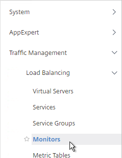
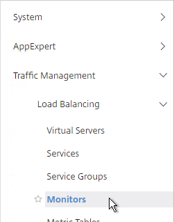
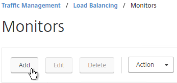
  1. In the NetScaler Configuration Utility, expand Traffic Management, expand Load Balancing, and click Monitors.
  2. On the right, click Add.
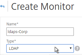
  3. Name the monitor ldaps-Corp or similar. The ldaps monitor logs into Active Directory, performs an LDAP query, and looks for a successful response. The monitor configuration has domain specific information so if you have multiple Active Directory domains, then you will need multiple ldaps monitors. Include the domain name in the monitor name.
  4. Change the Type to LDAP.
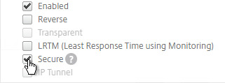
  5. Scroll down and check the box next to Secure.
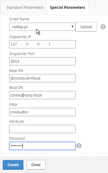
  6. Scroll back up and switch to the Special Parameters tab.
  7. On the Special Parameters tab, use the Script Name drop-down list to select the nsldap.pl file.
  8. In the Base DN field, enter your domain name in LDAP format (e.g. dc=company,dc=com)
  9. In the Bind DN field, enter the UPN login (e.g. ctxsvc@company.com) of a service account in the domain that can browse all objects. Any normal Domain User should be sufficient. Just make sure the password doesn’t expire.
  10. In the Filter field, enter cn=builtin. This limits the search results.
  11. In the Password field, enter the password for the service account. Make sure there is no semicolon in the password or the script will be unable to parse the parameters.
  12. Click Create.

    add lb monitor LDAP-Corp LDAP -scriptName nsldap.pl -dispatcherIP 127.0.0.1 -dispatcherPort 3013 -password Passw0rd -secure YES -baseDN "dc=corp,dc=local" -bindDN "corp\\ctxsvc" -filter cn=builtin
  13. If you have multiple domains then create additional monitors: one for each domain.

Servers

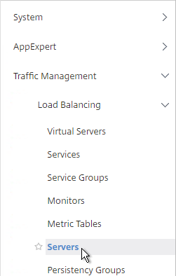
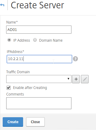
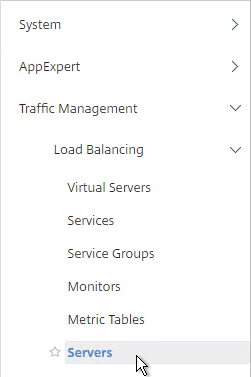
  1. On the left, expand Traffic Management, expand Load Balancing, and click Servers.
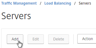
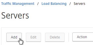
  2. On the right, click Add.
  3. Enter a descriptive server name, usually it matches the actual server name.
  4. Enter the IP address of the server.
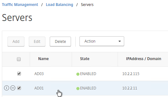
  5. Enter comments to describe the server. Click Create.

    add server AD01 10.2.2.11
    add server AD01 10.2.2.12
  6. Continue adding Domain Controllers.

Service Groups

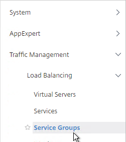
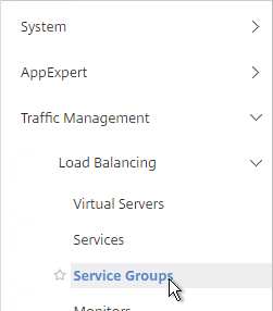
  1. On the left, expand Traffic Management, expand Load Balancing, and click Service Groups.
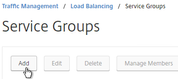
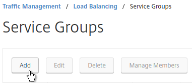
  2. On the right click Add
    .
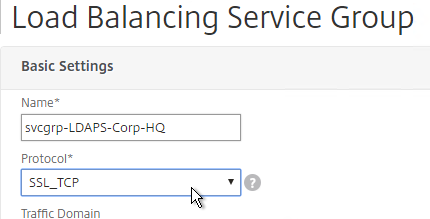
  3. You will create one Service Group per datacenter. Enter a name reflecting the name of the data center. Also, you will create a set of service groups per Active Directory domain so include the domain name.
  4. Change the Protocol to SSL_TCP. Scroll down and click OK.

  5. On the left, in the Service Group Members section, click where it says No Service Group Member.
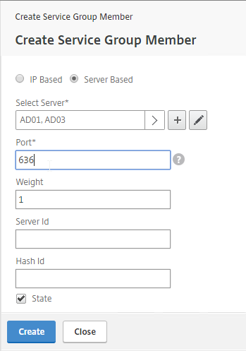
  6. If you did not create server objects, then enter the IP address of a Domain Controller in this datacenter. If you previously created a server object, then change the selection to Server Based, and select the server object. In the Port field, enter 636 (LDAPS).
    1. Note: Any Domain Controller you add to this list must have an SSL certificate installed. The easiest way to install SSL certificates on the Domain Controllers is with Active Directory Certificate Services since it installs the certificates automatically.
  7.  Click Create.
  8. Click OK.
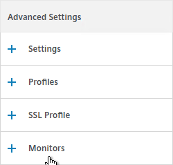
  9. On the right, in the Advanced Settings column, click Monitors.
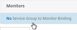
  10. On the left, in the Monitors section, click where it says No Service Group to Monitor Binding.
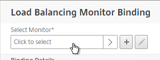
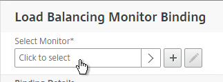
  11. Click the arrow next to Click to select.
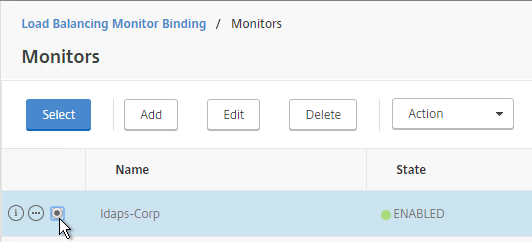
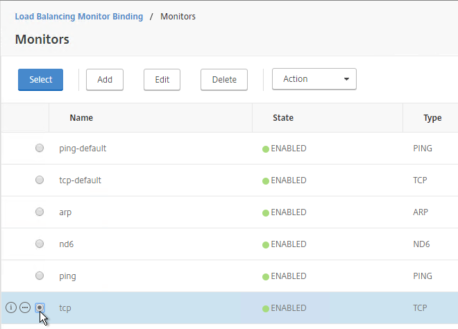
  12. Select your new LDAPS monitor and click Select.
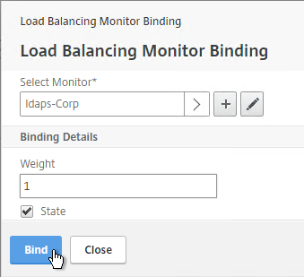
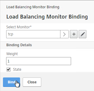
  13. Click Bind.
  14. To verify the member is up, click in the Service Group Members section.
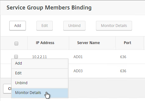
  15. Click the ellipsis next to a member and click Monitor Details.
  16. It should say Success – Probe succeeded. Click Close.
  17. If the monitor doesn’t work, use ldp.exe to verify the Domain Controller certificate.
  18. Click Close and Done to finish creating the Service Group.

    add serviceGroup svcgrp-LDAP-Corp SSL_TCP
    bind serviceGroup svcgrp-LDAP-Corp AD01 636
    bind serviceGroup svcgrp-LDAP-Corp AD02 636
    bind serviceGroup svcgrp-LDAP-Corp -monitorName LDAP-Corp
  19. Add additional service groups for Domain Controllers in each data center.

Virtual Server

  1. Create or import a certificate that matches the FQDN that resolves to the new Load Balancing VIP for LDAPS.
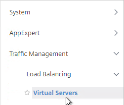
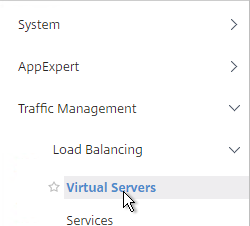
  2. On the left, expand Traffic Management, expand Load Balancing, and click Virtual Servers.

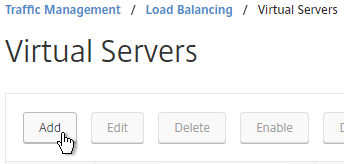
  3. On the right, click Add.
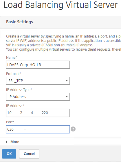
  4. Name it LDAPS-Corp-HQ-LB or similar. You will create one Virtual Server per datacenter so include the datacenter name. Also, each domain has a separate set of Virtual Servers so include the domain name.
  5. Change the Protocol drop-down to SSL_TCP.
  6. Enter a Virtual IP. This VIP cannot conflict with any other IP + Port already being used. You can use an existing VIP that is not already listening on TCP 636.
  7. Enter 636 as the Port. Click OK.
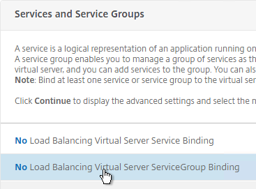
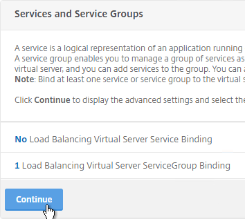
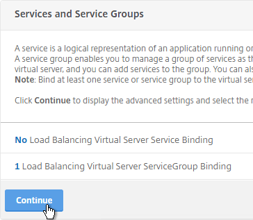
  8. On the left, in the Service Group section, click where it says No Load Balancing Virtual Server ServiceGroup Binding.
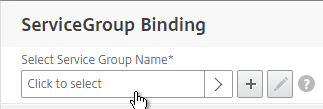
  9. Click the arrow next to Click to select.
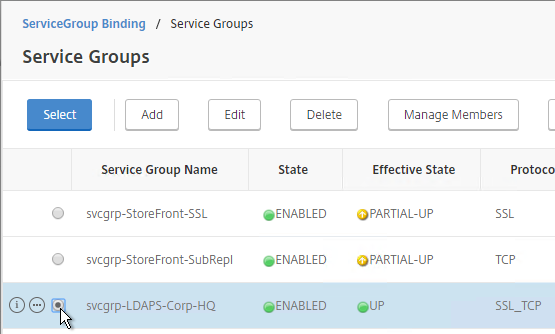
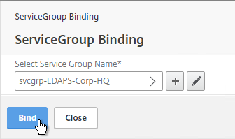
  10. Select the previously created Service Group and click Select.
  11. Click Bind.
  12. Click Continue.
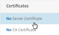
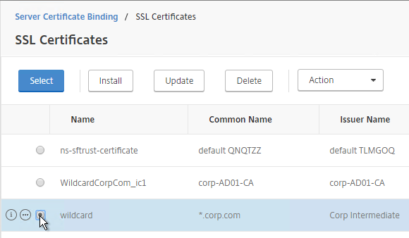
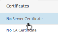
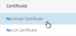
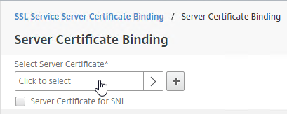
  13. On the left, in the Certificates section, click where it says No Server Certificate.
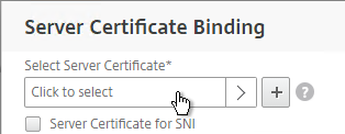
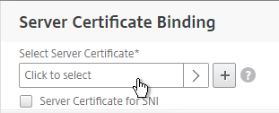
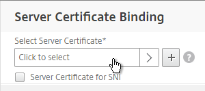
  14. Click the arrow next to Click to select.
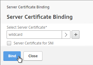
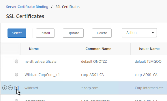
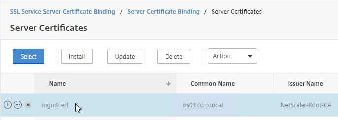
  15. Select a certificate that matches the FQDN that will resolve to this VIP. Click Select.
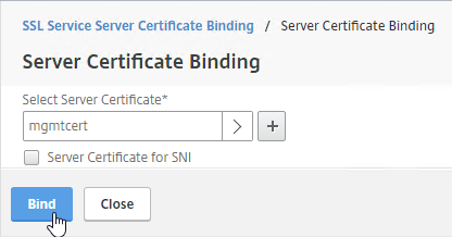
  16. Click Bind.
  17. Click Continue.

    add lb vserver lbvip-LDAP-Corp SSL_TCP 10.2.2.210 636 -persistenceType NONE -cltTimeout 9000
    
    bind lb vserver lbvip-LDAP-Corp svcgrp-LDAP-Corp
  18. If you haven’t enabled the Default SSL Profile, then perform other normal SSL configuration including: disable SSLv3, and bind a Modern Cipher Group.
    bind ssl vserver MyvServer -certkeyName MyCert
    
    set ssl vserver MyvServer -ssl3 DISABLED -tls11 ENABLED -tls12 ENABLED
    
    unbind ssl vserver MyvServer -cipherName ALL
    
    bind ssl vserver MyvServer -cipherName Modern
    
    bind ssl vserver MyvServer -eccCurveName ALL
  19. Click Done to finish creating the Virtual Server.
  20. The new Virtual Server should show as Up.
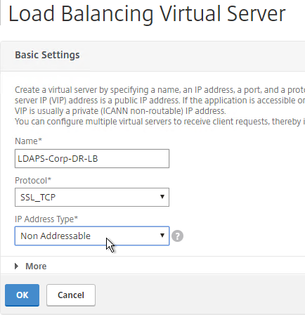
  21. Create additional Virtual Servers for each datacenter. These additional Virtual Servers do not need a VIP so change the IP Address Type to Non Addressable. Only the first Virtual Server will be directly accessible.

    add lb vserver lbvip-LDAP-Corp-Backup SSL_TCP 0.0.0.0 0
  22. Notice that the additional datacenter Virtual Servers show up with an IP Address of 0.0.0.0 and port of 0.
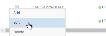
  23. After you are done creating a Virtual Server for each datacenter, click the ellipsis next to the primary datacenter’s Virtual Server and click Edit.
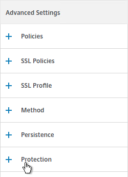
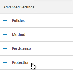
  24. On the right, in the Advanced Settings column, click Protection.
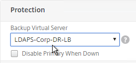
  25. On the left, in the Protection section, change the Backup Virtual Server to one of the other datacenter Virtual Servers. If all of the services in this datacenter are DOWN, the backup Virtual Server will be used instead. You can cascade multiple Virtual Servers using this method. Click OK and Done.

    set lb vserver lbvip-LDAP-Corp -backupVServer lbvip-LDAP-Corp-Backup

Next Steps

You may now use this Virtual IP in your LDAP authentication policies for NetScaler Gateway or NetScaler management login.

StoreFront Load Balancing – NetScaler 11.1

Last Modified: Nov 7, 2020 @ 6:35 am

Navigation

Monitor

Note: This is a Perl monitor, which uses the NSIP as the source IP. You can use RNAT to override this as described in CTX217712 How to Force scriptable monitor to use SNIP in Netscaler in 10.5.

  1. On the left, expand Traffic Management, expand Load Balancing, and click Monitors.
  2. On the right, click Add.
  3. Name it StoreFront or similar.
  4. Change the Type drop-down to STORERONT.
  5. If you will use SSL to communicate with the StoreFront servers, then scroll down, and check the box next to Secure.
  6. Scroll up, and switch to the Special Parameters tab.
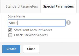
  7. In the Store Name field, enter the name of your store (e.g. MyStore) without spaces.
  8. Click Create.

    add lb monitor StoreFront STOREFRONT -scriptName nssf.pl -dispatcherIP 127.0.0.1 -dispatcherPort 3013 -secure YES -storename Store

Servers

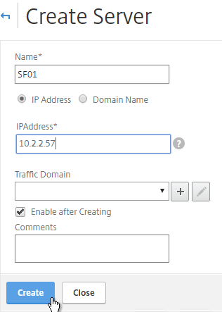
  1. On the left, expand Traffic Management, expand Load Balancing, and click Servers.
  2. On the right, click Add.
  3. Enter a descriptive server name, usually it matches the actual server name.
  4. Enter the IP address of the server.
  5. Enter comments to describe the server. Click Create.
  6. Continue adding StoreFront servers.

    add server SF01 10.2.2.57
    add server SF02 10.2.2.58

Service Group

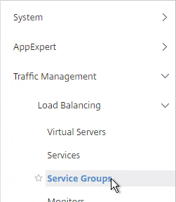
  1. On the left, expand Traffic Management, expand Load Balancing, and click Service Groups.

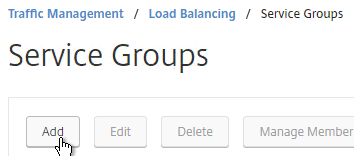
  2. On the right, click Add.
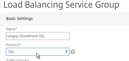
  3. Give the Service Group a descriptive name (e.g. svcgrp-StoreFront-SSL).
  4. Change the Protocol to HTTP or SSL. If the protocol is SSL, ensure that the StoreFront Monitor has Secure checked.
  5. Scroll down and click OK.

  6. Click where it says No Service Group Member.
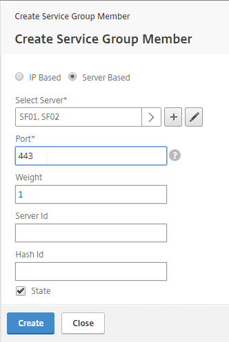
  7. If you did not create server objects then enter the IP address of a StoreFront Server. If you previously created a server object then change the selection to Server Based and select the server objects.
  8. Enter 80 or 443 as the port. Then click Create.
  9. Click OK.
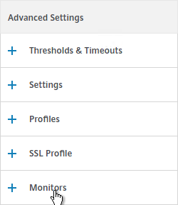
  10. On the right, under Advanced Settings , click Monitors.
  11. Click where it says says No Service Group to Monitor Binding.
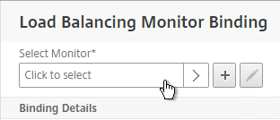
  12. Click the arrow next to Click to select.
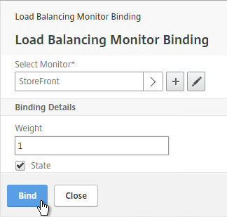
  13. Select your StoreFront monitor and click Select.
  14. Then click Bind.
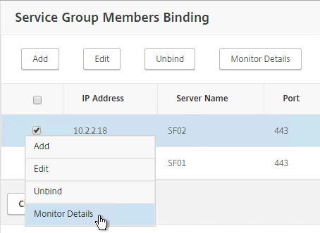
  15. To verify that the monitor is working, on the left, in the Service Group Members section, click the Service Group Members line.
  16. Click the ellipsis next to a member and click Monitor Details.
  17. The Last Response should be Success – Probe succeeded. Click Close twice.
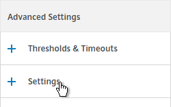
  18. On the right, under Advanced Settings, click Settings.
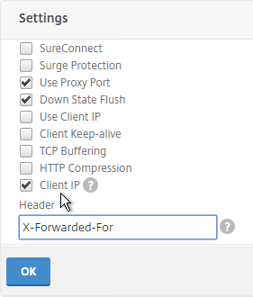
  19. On the left, in the Settings section, check the box for Client IP and enter X-Forwarded-For as the Header. Then click OK.
  20. Then click Done.

    add serviceGroup svcgrp-StoreFront-SSL SSL -maxClient 0 -maxReq 0 -cip ENABLED X-Forwarded-For
    
    bind serviceGroup svcgrp-StoreFront-SSL SF01 443
    bind serviceGroup svcgrp-StoreFront-SSL SF02 443
    bind serviceGroup svcgrp-StoreFront-SSL -monitorName StoreFront
  21. If the Service Group is http and you don’t have certificates installed on your StoreFront servers (aka SSL Offload) then you’ll need to enable loopback in StoreFront.
    1. In StoreFront 3.5 and newer, you enable it in the GUI console.
    2. In StoreFront 3.0, run the following commands on the StoreFront 3.0 servers as detailed at Citrix Blog Post What’s New in StoreFront 3.0.
      & "C:\Program Files\Citrix\Receiver StoreFront\Scripts\ImportModules.ps1"
      
      Set-DSLoopback -SiteId 1 -VirtualPath /Citrix/StoreWeb -Loopback OnUsingHttp

Load Balancing Virtual Server

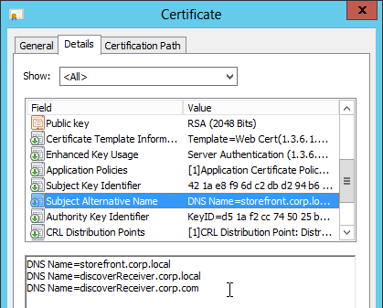
  1. Create or install a certificate that will be used by the SSL Offload Virtual Server. This certificate must match the DNS name for the load balanced StoreFront servers. For email discovery in Citrix Receiver, the certificate must either be a wildcard (*.corp.local) or have a subject alternative name for discoverReceiver.domain.com (domain.com = email address suffix)
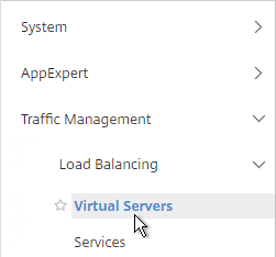
  2. On the left, under Traffic Management > Load Balancing, click Virtual Servers.

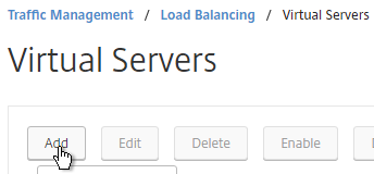
  3. On the right click Add.
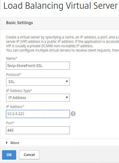
  4. Name it lbvip-StoreFront-SSL or similar.
  5. Change the Protocol to SSL.
  6. Specify a new internal VIP.
  7. Enter 443 as the Port.
  8. Click OK.

    add lb vserver lbvip-StoreFront-SSL SSL 10.2.2.221 443 -persistenceType SOURCEIP -timeout 60
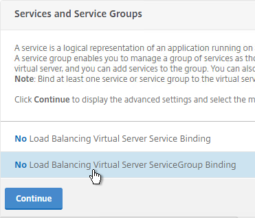
  9. On the left, in the Services and Service Groups section, click where it says No Load Balancing Virtual Server ServiceGroup Binding.
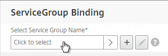
  10. Click the arrow next to Click to select.
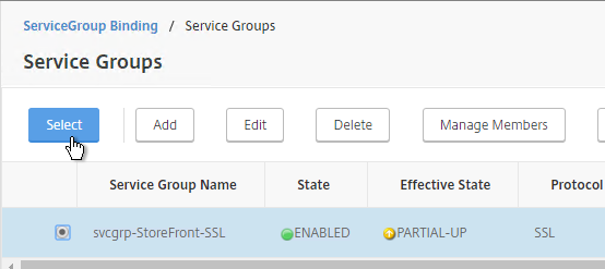
  11. Select your StoreFront Service Group and click Select.
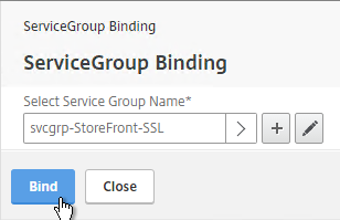
  12. Click Bind.

    bind lb vserver lbvip-StoreFront-SSL svcgrp-StoreFront-SSL
  13. Click Continue.
  14. Click where it says No Server Certificate.
  15. Click the arrow next to Click to select.
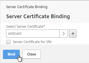
  16. Select the certificate for this StoreFront Load Balancing Virtual Server and click Select.
  17. Click Bind.

    bind ssl vserver lbvip-StoreFront-SSL -certkeyName WildCorpCom
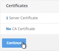
  18. Click Continue.
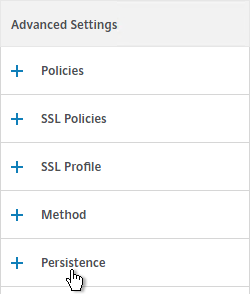
  19. On the right, in the Advanced Settings column, click Persistence.
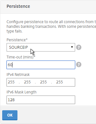
  20. On the left, in the Persistence section, select SOURCEIP. Do NOT use COOKIEINSERT persistence or Android devices will not function correctly.
  21. Set the timeout to match the timeout of Receiver for Web.
  22. The IPv4 Netmask should default to 32 bits.
  23. Click OK.
  24. If the NetScaler communicates with the StoreFront servers using HTTP (aka SSL Offload – 443 on client-side, 80 on server-side), and if you have enabled the Default SSL Profile, then you’ll either need to edit the Default SSL Profile to include the SSL Redirect option, or create a new custom SSL Profile with the SSL Redirect option enabled, and then bind the custom SSL Profile to this vServer.
  25. If the default SSL Profile is not enabled, then you’ll need to edit the SSL Parameters section on the vServer, and at the top right, check the box next to SSL Redirect. Otherwise the Receiver for Web page will never display.
  26. set ssl vserver lbvip-StoreFront-SSL -sslRedirect ENABLED -ssl3 DISABLED
  27. If you haven’t enabled the Default SSL Profile, then perform other normal SSL configuration including: disable SSLv3, bind a Modern Cipher Group, and enable Strict Transport Security.
    bind ssl vserver lbvip-StoreFront-SSL -certkeyName MyCert
    
    set ssl vserver lbvip-StoreFront-SSL -ssl3 DISABLED -tls11 ENABLED -tls12 ENABLED
    
    unbind ssl vserver lbvip-StoreFront-SSL -cipherName ALL
    
    bind ssl vserver lbvip-StoreFront-SSL -cipherName Modern
    
    bind ssl vserver lbvip-StoreFront-SSL -eccCurveName ALL
    
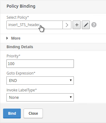
    bind lb vserver lbvip-StoreFront-SSL -policyName insert_STS_header -priority 100 -gotoPriorityExpression END -type RESPONSE

When connecting to StoreFront through load balancing, if you want to put the server name on the StoreFront webpage so you can identify the server, see Nicolas Ignoto Display server name with Citrix StoreFront 3.
Server name is displayed

SSL Redirect – SSL Load Balancing vServer Method

Users must enter https:// when navigating to the StoreFront website. To make it easier for the users, enable SSL Redirection.

This procedure details the SSL Load Balancing vServer method of performing an SSL redirect. An alternative is to use the Responder method.

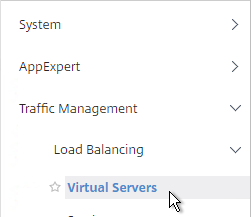
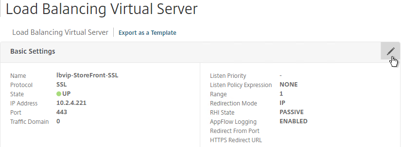
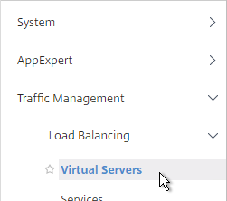
  1. On the left, under Traffic Management > Load Balancing, click Virtual Servers.

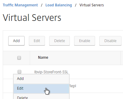
  2. On the right, find the SSL Virtual Server you’ve already created, click the ellipsis next to it and click Edit.
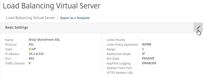
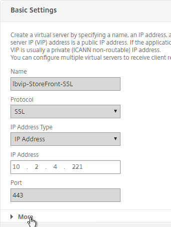
  3. In the Basic Settings section, click the pencil icon.
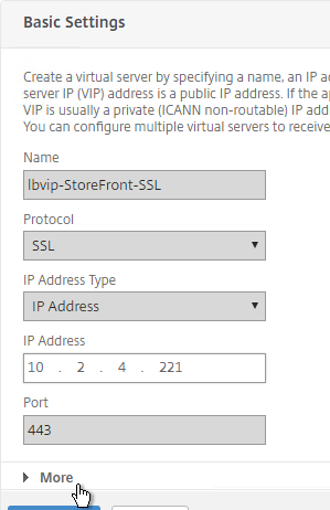
  4. Click the More link.
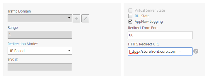
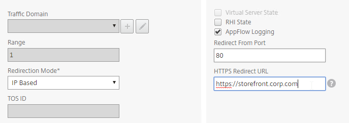
  5. In the Redirect from Port field, enter 80.
  6. In the HTTPS Redirect URL field, enter your StoreFront Load Balancing URL (e.g. https://storefront.corp.com).
  7. Scroll down and click Continue twice.

    set lb vserver lbvip-StoreFront-SSL -redirectFromPort 80 -httpsRedirectUrl https://storefront.corp.com
  8. This method does not add any new vServers to the list so it’s not easy to see if this is configured.

StoreFront Base URL

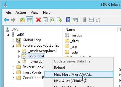
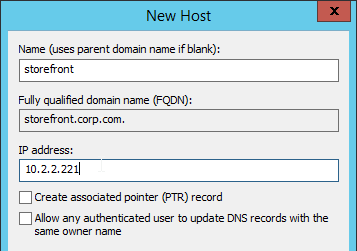
  1. Create a DNS Host record that resolves to the new VIP.
  2. The DNS name for StoreFront load balancing must be different than the DNS name for NetScaler Gateway. Unless you are following the Single FQDN procedure.

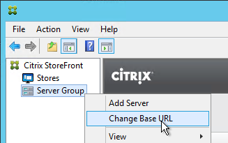
  3. In the Citrix StoreFront console, right-click Server Group and click Change Base URL.
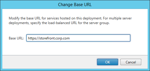
  4. Enter the new Base URL in https://storefront.corp.com format. This must match the certificate that is installed on the load balancer. Click OK.

Subscription Replication Load Balancing

If you have multiple StoreFront clusters (separate datacenters), you might want to replicate subscriptions between them. StoreFront subscription replication uses TCP port 808. To provide High Availability for this service, load balance TCP port 808 on the StoreFront servers. See Configure subscription synchronization at Citrix Docs for more information.

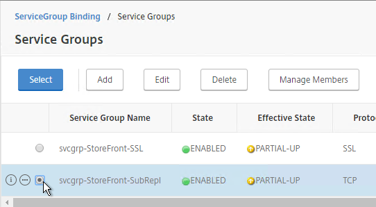
  1. On the left, expand Traffic Management, expand Load Balancing, and click Service Groups.

  2. On the right, click Add.
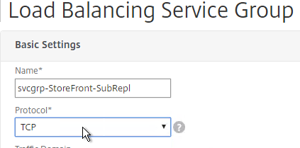
  3. Give the Service Group a descriptive name (e.g. svcgrp-StoreFront-SubRepl).
  4. Change the Protocol to TCP.
  5. Scroll down and click OK.
  6. Click where it says No Service Group Member.
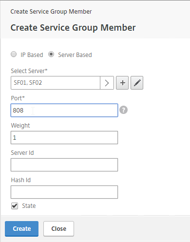
  7. Change the selection to Server Based and select the StoreFront servers.
  8. Enter 808 as the port. Then click Create.

  9. Click OK.
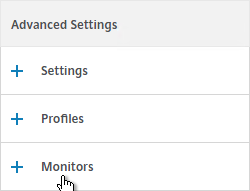
  10. On the right, under Advanced Settings, click Monitors.
  11. On the left, in the Monitors section, click where it says No Service Group to Monitor Binding.
  12. Click the arrow next to Click to select.
  13. Select the tcp monitor and click Select.
  14. Then click Bind and click Done.

    add serviceGroup svcgrp-StoreFront-FavRepl TCP
    bind serviceGroup svcgrp-StoreFront-FavRepl SF01 808
    bind serviceGroup svcgrp-StoreFront-FavRepl SF02 808
  15. On the left, under Traffic Management > Load Balancing, click Virtual Servers.

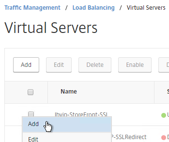
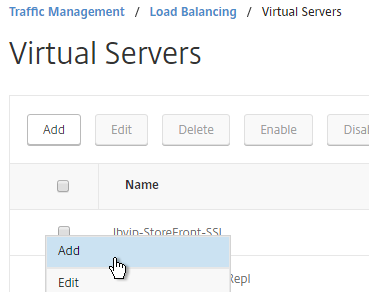
  16. On the right, click the ellipsis next to the existing StoreFront Load Balancing vServer, and click Add.
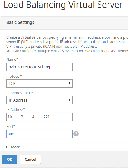
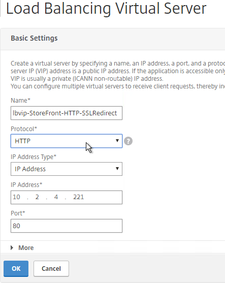
  17. Name it lbvip-StoreFront-SubRepl or similar.
  18. Change the Protocol to TCP.
  19. Specify the same VIP that you used for SSL Load Balancing of StoreFront.
  20. Enter 808 as the Port.
  21. Click OK.
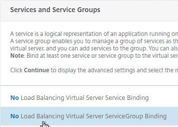
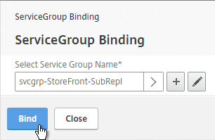
  22. Click where it says No Load Balancing Virtual Server ServiceGroup Binding.

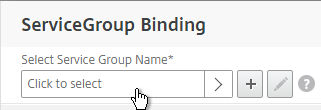
  23. Click the arrow next to Click to select.
  24. Select your StoreFront Subscription Replication Service Group and click Select.
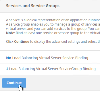
  25. Click Bind.
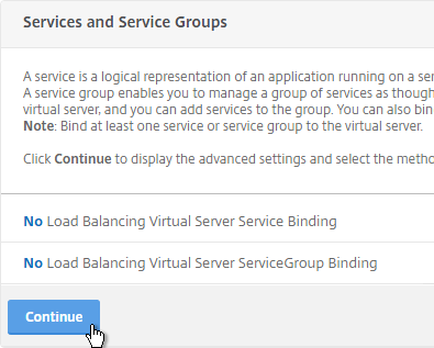
  26. Click Continue.
  27. Then click Done.

    add lb vserver lbvip-StoreFront-FavRepl TCP 10.2.2.201 808 -persistenceType NONE
    
    bind lb vserver lbvip-StoreFront-FavRepl svcgrp-SF-FavRepl

Related Posts

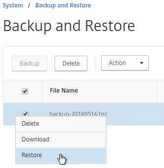
SSL Virtual Servers – NetScaler 11.1

Last Modified: Nov 7, 2020 @ 6:34 am

This page contains generic SSL instructions for all SSL Virtual Servers including: Load Balancing, NetScaler Gateway, Content Switching, and AAA.

Navigation

💡 = Recently Updated

Change Log

Cipher Group

References:

To create a custom secure cipher group:

  1. Ryan Butler has a PowerShell script at Github that can automate NetScaler SSL configuration to get an A+.
  2. The easiest way to create a cipher group is from the CLI. See Citrix Blogs Scoring an A+ at SSLlabs.com with Citrix NetScaler – 2016 update for cipher group CLI commands.
  3. The last cipher is only needed for Windows XP machines. It doesn’t actually require SSL3. If you don’t need to support Windows XP, then skip that command.
    add ssl cipher custom-ssllabs-cipher
    bind ssl cipher custom-ssllabs-cipher -cipherName TLS1.2-ECDHE-RSA-AES256-GCM-SHA384
    bind ssl cipher custom-ssllabs-cipher -cipherName TLS1.2-ECDHE-RSA-AES128-GCM-SHA256
    bind ssl cipher custom-ssllabs-cipher -cipherName TLS1.2-ECDHE-RSA-AES-256-SHA384
    bind ssl cipher custom-ssllabs-cipher -cipherName TLS1.2-ECDHE-RSA-AES-128-SHA256
    bind ssl cipher custom-ssllabs-cipher -cipherName TLS1-ECDHE-RSA-AES256-SHA
    bind ssl cipher custom-ssllabs-cipher -cipherName TLS1-ECDHE-RSA-AES128-SHA
    bind ssl cipher custom-ssllabs-cipher -cipherName TLS1.2-DHE-RSA-AES256-GCM-SHA384
    bind ssl cipher custom-ssllabs-cipher -cipherName TLS1.2-DHE-RSA-AES128-GCM-SHA256
    bind ssl cipher custom-ssllabs-cipher -cipherName TLS1-DHE-RSA-AES-256-CBC-SHA
    bind ssl cipher custom-ssllabs-cipher -cipherName TLS1-DHE-RSA-AES-128-CBC-SHA
    bind ssl cipher custom-ssllabs-cipher -cipherName TLS1-AES-256-CBC-SHA
    bind ssl cipher custom-ssllabs-cipher -cipherName TLS1-AES-128-CBC-SHA
    bind ssl cipher custom-ssllabs-cipher -cipherName SSL3-DES-CBC3-SHA
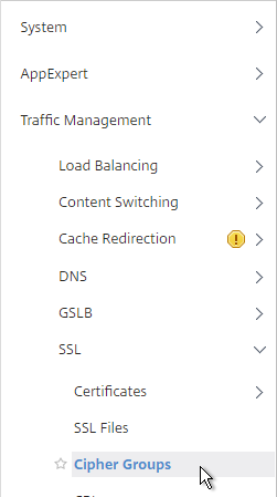
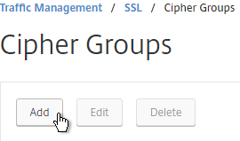
  4. Or you can create the cipher group using the GUI. Go to Traffic Management > SSL > Cipher Groups.
  5. On the right, click Add.
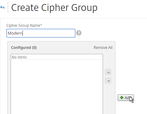
  6. Name it Modern or similar.
  7. In the middle, click Add.
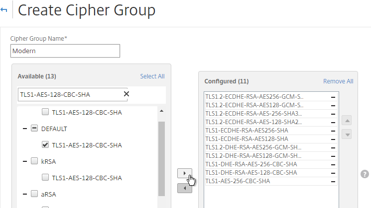
  8. Use the search box to find a particular cipher.
  9. Check the box next to one of the results and click the arrow to move it to the right. See Citrix Blogs Scoring an A+ at SSLlabs.com with Citrix NetScaler – 2016 update for recommended ciphers. The recommended ciphers vary based on the hardware platform and support for older clients.
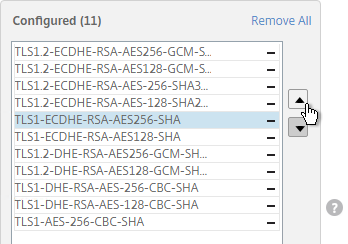
  10. Use the up and down arrows to order the ciphers. NetScaler prefers the ciphers on top of the list, so the ciphers at the top of the list should be the most secure ciphers.
  11. Click Create when done.

Strict Transport Security Rewrite Policy

To get an A+ at SSLLabs.com, you need to insert the Strict-Transport-Security HTTP header in the responses. NetScaler Rewrite Policy can do this.

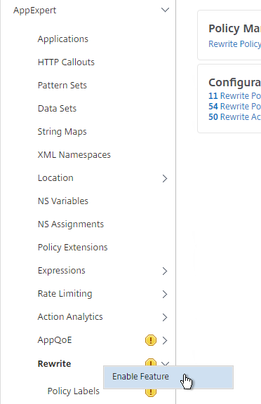
  1. Go to AppExpert > Rewrite, right-click Rewrite, and click Enable Feature.
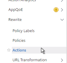
  2. Go to AppExpert > Rewrite > Actions.
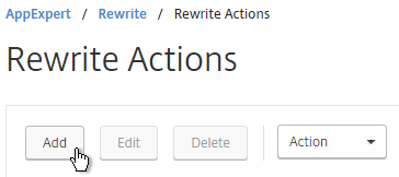
  3. On the right, click Add.
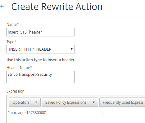
  4. Name the action insert_STS_header or similar.
  5. The Type should be INSERT_HTTP_HEADER.
  6. The Header Name should be Strict-Transport-Security.
  7. The Expression should be the following:
    "max-age=157680000"

  8. Click Create.
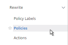
  9. On the left, go to AppExpert > Rewrite > Policies.
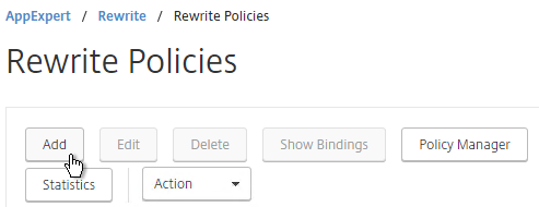
  10. On the right, click Add.
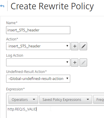
  11. Name it insert_STS_header or similar.
  12. Select the previously created Action.
  13. In the Expression box, enter HTTP.REQ.IS_VALID.
  14. Click Create.
  15. Now you can bind this Rewrite Response policy to HTTP-based SSL vServers.
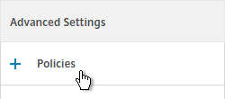
  16. When editing an SSL vServer, if the Policies section doesn’t exist on the left, then add it from the Advanced Settings column on the right.
  17. In the Policies section on the left, click the plus icon.
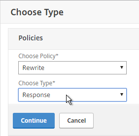
  18. Select Rewrite > Response and click Continue.
  19. Then select the STS Rewrite Policy and click Bind.
enable ns feature rewrite

add rewrite action insert_STS_header insert_http_header Strict-Transport-Security "\"max-age=157680000\""

add rewrite policy insert_STS_header true insert_STS_header

bind lb vserver MyvServer -policyName insert_STS_header -priority 100 -gotoPriorityExpression END -type RESPONSE

Default SSL Profile

You can use SSL Profiles to package several SSL settings together and apply the settings package (Profile) to SSL vServers and SSL Services. These settings include: disable SSLv3, bind ciphers, bind ECC curves, etc.

There are default SSL Profiles, and there are custom SSL Profiles. The default SSL Profiles are disabled by default. Once the default SSL Profiles are enabled, the default setttings apply to all SSL vServers and all SSL Services, unless you bind a custom SSL Profile. Also, once default is enabled, it’s not possible to disable it.

  • Some features of custom SSL Profiles require default SSL Profiles to be enabled. For example, you cannot configure ciphers in a custom SSL Profile unless the default SSL Profiles are enabled.

If you enable the default SSL Profiles, then it’s not possible to configure SNI for backend (services and service groups).

Default SSL Profiles are intended to provide a baseline SSL configuration for all newly created SSL Virtual Servers and SSL Services. You can still create Custom SSL Profiles to override the Default SSL Profiles.

Enabling the default SSL profile will wipe out any SSL configuration on SSL entities (e.g. SSL Virtual Servers) that do not have a custom SSL profile bound. Citrix offers a script that can read your existing SSL entity SSL configuration and convert them to custom SSL Profiles. See Enabling the Default Profiles at Citrix Docs. The default_profile_scriptcan be downloaded from an individual NetScaler ADC firmware download page under Additional Components. The commands output by the script won’t work until the default SSL Profile is enabled.  💡

To enable the Default SSL profiles:

  1. Make sure you are connected to the appliance using http and not https.
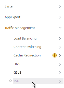
  2. Go to Traffic Management > SSL.
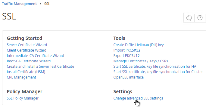
  3. On the right, in the right column, click Change advanced SSL settings.
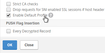
  4. Near the bottom, check the box next to Enable Default Profile. Note: this will change SSL settings on all SSL Virtual Servers to match the default SSL profile. You might want to do this during a maintenance window. Click OK when done.
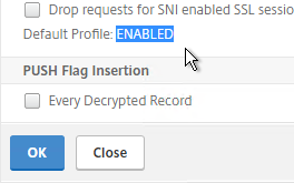
  5. If you go back into Advanced SSL Settings, notice that the Default Profile is enabled and there’s no way to disable it.
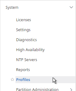
  6. To change the default SSL profile, on the left, go to System > Profiles.
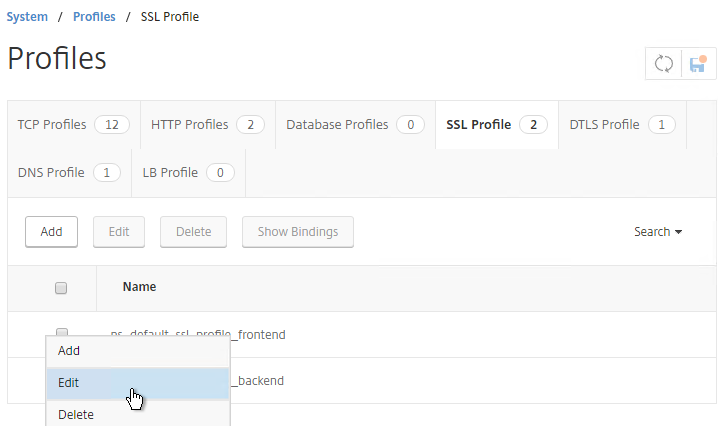
  7. On the right, switch to the SSL Profile tab.
  8. Click the ellipsis next to the frontend or backend default profile and click Edit. Frontend = client-side connections to SSL vServers. Backend = server-side connections (SSL Services and Service Groups).
  9. Or you can create a new custom SSL profile.
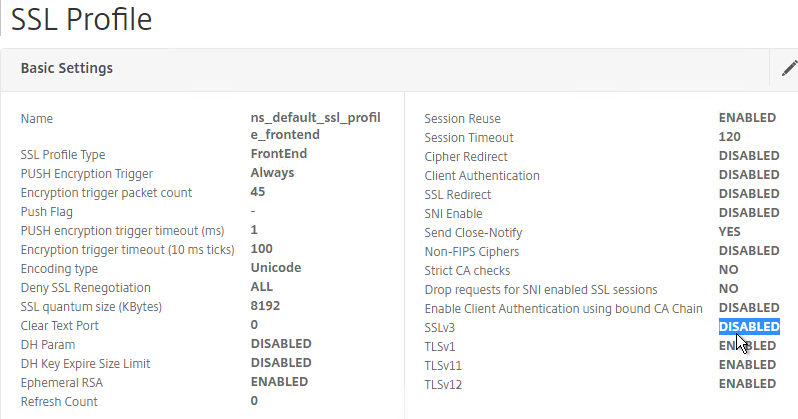
  10. Notice that SSLv3 is disabled by default.
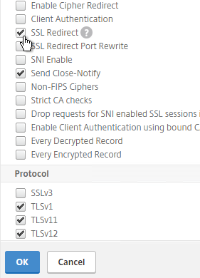
  11. If you do any SSL Offload (SSL on the client side, HTTP on the server side) then you’ll need to edit the Basic Settings section and enable SSL Redirect. Or you can create a new SSL Profile with this option enabled. It’s near the bottom of the section. With this option enabled, any 301/302 redirects from the server with HTTP locations are rewritten to HTTPS locations. You might need this option for StoreFront load balancing if doing SSL Offload.
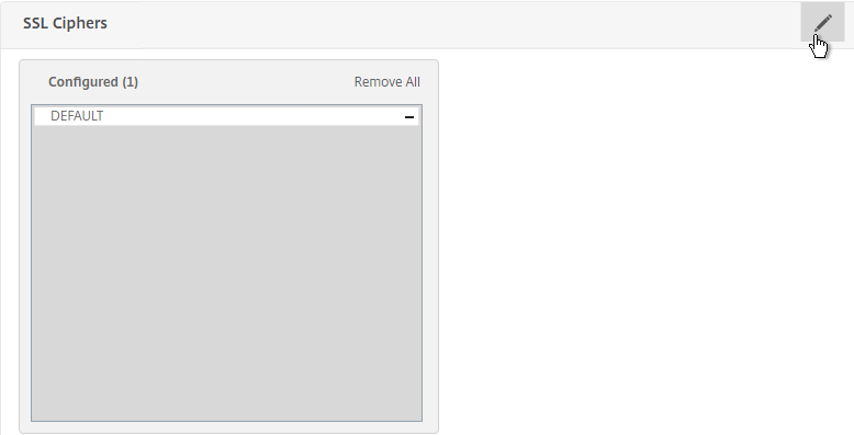
  12. Scroll down to the SSL Ciphers section and click the pencil icon.
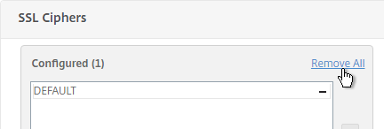
  13. Click Remove All and click OK. You must click OK before binding the custom cipher group.
  14. Click the pencil icon again.
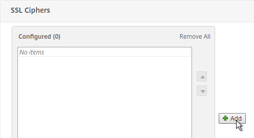
  15. Click Add.
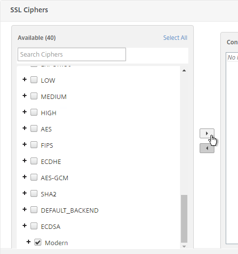
  16. Scroll down and select your custom cipher group. Then click the arrow to move it to the right. Then click OK.
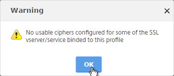
  17. Click OK when you see the No usable ciphers message. Then click Done to close the SSL Profile.
  18. If you edit one of your SSL Virtual Servers (e.g. Load Balancing vServer), there’s an SSL Profile section indicating that the default profile is being used. You can change the binding to a different SSL Profile.
  19. SSL Profiles do not include forcing Strict Transport Security. You’ll still need to create the STS Rewrite Policy and bind it to every SSL vServer as detailed in the next section.

Bind Certificate, Bind Cipher Group, Disable SSLv3, Enable STS

Whether you use SSL Profiles or not, you need to bind certificates and STS Rewrite Policy to every SSL vServer.

If you enabled the Default SSL Profiles feature, you can either leave it set to the Default SSL Profile; or you can change it to a Custom SSL Profile. Or you can bind an SSL Profile without enabling the Default SSL Profiles. If you don’t use the SSL Profiles feature, then you’ll need to manually configure ciphers and SSL settings on every SSL vServer.

Do the following on every SSL vServer:

  1. When creating an SSL Virtual Server (e.g. SSL Load Balancing vServer), on the left, in the Certificates section, click where it says No Server Certificate.
  2. Click where it says Click to select.
  3. Select a certificate and click Select.
  4. Click Bind.

    bind ssl vserver MyvServer -certkeyName MyCert
  5. If you want to bind a custom SSL Profile, if Default SSL Profile is enabled, in the SSL Profile section on the left, click the pencil icon.
  6. If the SSL Profile section isn’t on the left, then on the right, in the Advanced Settings section, click SSL Profile
  7. Select your custom SSL Profile and click OK.
  8. If you didn’t bind an SSL Profile, on the left, in the SSL Parameters section, click the pencil icon.
  9. Uncheck the box next to SSLv3. Make sure TLSv11 and TLSv12 are enabled. Click OK.

    set ssl vserver MyvServer -ssl3 DISABLED -tls11 ENABLED -tls12 ENABLED
  10. If you didn’t bind an SSL Profile, scroll down to the SSL Ciphers section and click the pencil icon.
  11. Click Remove All and click OK. You must click OK before binding the custom cipher group.
  12. Click the pencil icon again.
  13. Click Add.
  14. Scroll down and select your custom cipher group. Then click the arrow to move it to the right. Then click OK.
  15. Click OK when you see the No usable ciphers message.

    unbind ssl vserver MyvServer -cipherName ALL
    bind ssl vserver MyvServer -cipherName Modern
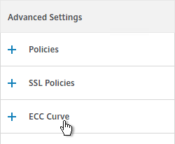
  16. SSL Virtual Servers created on newer versions of NetScaler will automatically have ECC Curves bound to them. However, if this appliance was upgraded from an older version then the ECC Curves might not be bound. If you are not using SSL Profile, then on the right, in the Advanced Settings section, click ECC Curve.
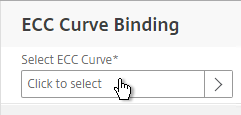
  17. On the left, in the ECC Curve section, click where it says No ECC Curve.
  18. Click to select.
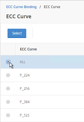
  19. Choose ALL and click Select.
  20. Click Bind.

    bind ssl vserver MyvServer -eccCurveName ALL
  21. If the Policies section doesn’t exist on the left, then add it from the Advanced Settings column on the right.
  22. In the Policies section on the left, click the plus icon.
  23. Select Rewrite > Response and click Continue.
  24. Select the STS Rewrite Policy and click Bind.

    bind lb vserver MyvServer -policyName insert_STS_header -priority 100 -gotoPriorityExpression END -type RESPONSE

If you experience SSL performance problems on a NetScaler MPX, Citrix CTX207005 Performance Issues with NetScaler MPX SSL recommends creating and binding the following TCP Profile:  💡

add ns tcpProfile tcp_test -WS ENABLED -SACK ENABLED -maxBurst 20 -initialCwnd 8 -bufferSize 4096000 -flavor BIC -dynamicReceiveBuffering DISABLED -sendBuffsize 4096000

SSL Tests

After you’ve created an SSL Virtual Server, run the following tests:

SSL Redirect – SSL Load Balancing vServer Method

New in NetScaler 11.1, you can configure SSL Redirect directly in an SSL Load Balancing vServer (port 443) instead of creating a separate HTTP (port 80) Load Balancing vServer.

Limitations:

  • This is only an option for SSL Load Balancing vServers; it’s not configurable in Gateway vServers or Content Switching vServers.
  • Only one Redirect URL can be specified. Alternatively, the Responder method can handle multiple FQDNs to one VIP (e.g. wildcard certificate) and/or IP address URLs.

To configure an SSL Load Balancing vServer to redirect from HTTP to HTTPS:

  1. Edit the SSL Load Balancing vServer (port 443).
  2. In the Basic Settings section, click the pencil icon.
  3. Click More.
  4. In the Redirect from Port field, enter 80.
  5. In the HTTPS Redirect URL field, enter https://MyFQDN. Click Continue twice.

SSL Redirect – Down vServer Method

If you created an SSL Virtual Server that only listens on SSL 443, then users must enter https:// when navigating to the website. To make it easier for the users, create another load balancing Virtual Server on the same VIP but listens on HTTP 80 and then redirects the user’s browser to reconnect on SSL 443.

The Down Virtual Server Method is easy, but the Redirect Virtual Server must be down in order for the redirect to take effect. Another option is to use Responder policies to perform the redirect.

To create the down Redirect Virtual Server:

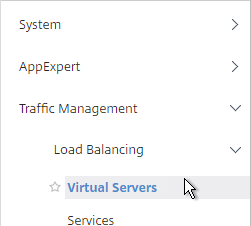
  1. On the left, under Traffic Management > Load Balancing, click Virtual Servers.

  2. On the right, find an SSL Virtual Server you’ve already created, click the ellipsis next to it, and click Add. Doing it this way copies some of the data from the already created Virtual Server.
  3. Or if you are redirecting NetScaler Gateway, create a new Load Balancing vServer with the same VIP as the Gateway.
  4. Change the name to indicate that this new Virtual Server is an SSL Redirect.
  5. Change the Protocol to HTTP on Port 80.
  6. The IP Address should already be filled in. It must match the original SSL Virtual Server (or Gateway vServer). Click OK.
  7. Don’t select any services. This vServer must intentionally be marked down so the redirect will take effect. Click Continue.
  8. On the right, in the Advanced Settings column, click Protection.
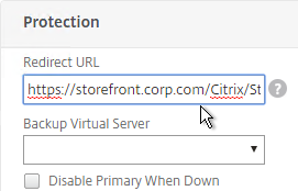
  9. In the Redirect URL field, enter the full URL including https://. For example: https://storefront.corp.com/Citrix/StoreWeb. Click OK.

  10. Click Done.
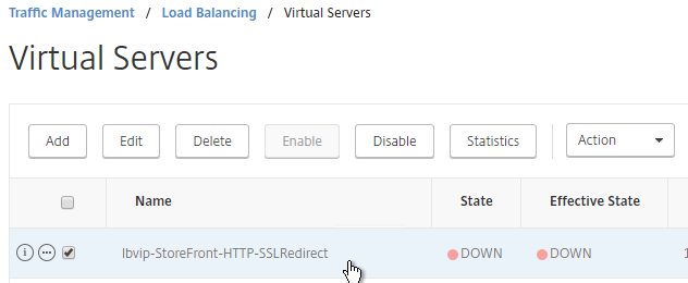
  11. When you view the SSL redirect Virtual Server in the list, it will have a state of DOWN. That’s OK. The Port 80 Virtual Server must be DOWN for this redirect method to work.

SSL Redirect – Responder Method

The Down Virtual Server Method is easy, but the Redirect Virtual Server must be down in order for the redirect to take effect. Another option is to use Responder policies to perform the redirect. This method requires the Redirect Virtual Server to be UP.

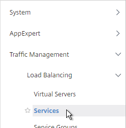
  1. Create a dummy Load Balancing service. This dummy service can be bound to multiple Redirect Virtual Servers. Go to Traffic Management > Load Balancing > Services.
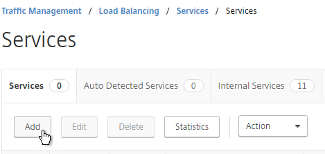
  2. On the right, click Add.
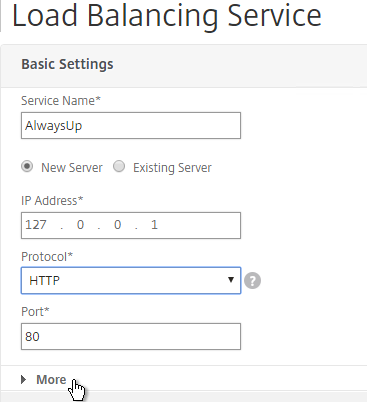
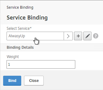
  3. Name it AlwaysUp or similar.
  4. Use a loopback IP address (e.g. 127.0.0.1). After the service is created, it changes to a NetScaler-owned IP.
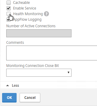
  5. Click the More link.
  6. This dummy service must always be UP so uncheck the box next to Health Monitoring. Click OK and then click Done.

    add server 127.0.0.1 127.0.0.1
    add service AlwaysUp 127.0.0.1 HTTP 80 -healthMonitor NO
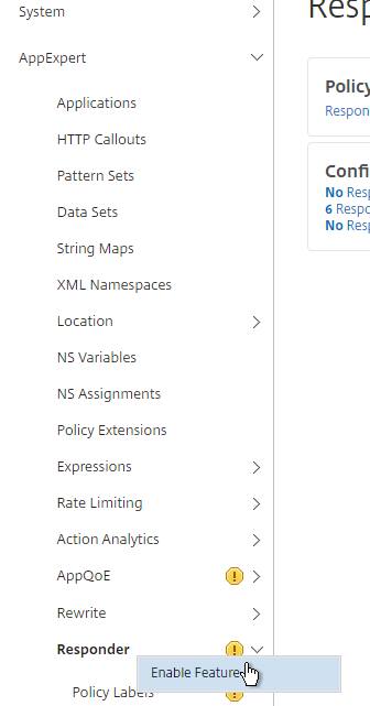
  7. On the left, expand AppExpert and click Responder.
  8. If Responder is not enabled, right-click Responder and click Enable Feature.

    enable ns feature RESPONDER
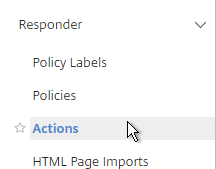
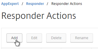
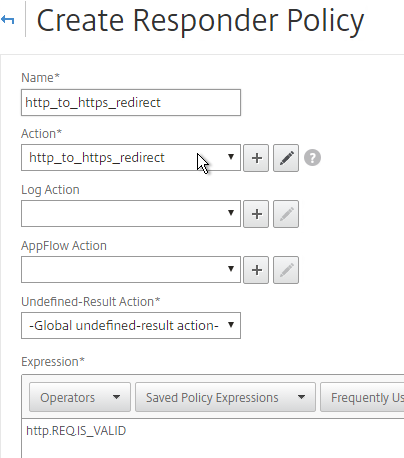
  9. Under Responder, click Actions.
  10. On the right, click Add.
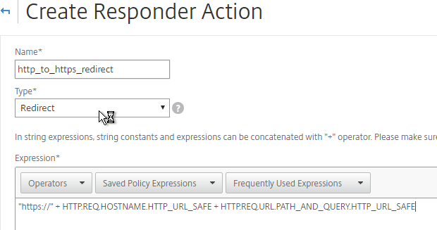
  11. Give the action a name.
  12. Change the Type to Redirect.
  13. Enter an expression. The following expression can be used by multiple Redirect Virtual Servers since it redirects to https on the same URL the user entered in the browser. Or you can create a Responder Action with a more specific Target. Click Create.
    "https://" + HTTP.REQ.HOSTNAME.HTTP_URL_SAFE + HTTP.REQ.URL.PATH_AND_QUERY.HTTP_URL_SAFE

    add responder action http_to_ssl_redirect_responderact redirect "\"https://\" + HTTP.REQ.HOSTNAME.HTTP_URL_SAFE + HTTP.REQ.URL.PATH_AND_QUERY.HTTP_URL_SAFE" -responseStatusCode 302
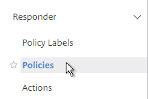
  14. On the left, under Responder, click Policies.
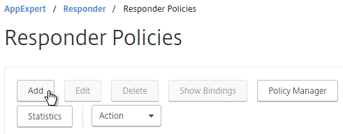
  15. On the right, click Add.
  16. Give the policy a name.
  17. Select the previously created Responder action.
  18. For the expression, enter the following. Then click Create.
    HTTP.REQ.IS_VALID

    add responder policy http_to_ssl_redirect_responderpol HTTP.REQ.IS_VALID http_to_ssl_redirect_responderact
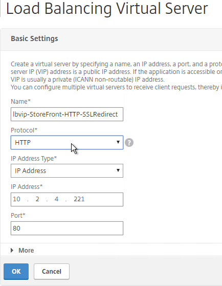
  19. Create a Load Balancing Virtual Server with Protocol HTTP and Port 80. The VIP should match an existing SSL Virtual Server or NetScaler Gateway Virtual Server.

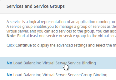
  20. Bind the AlwaysUp service and click Bind. Then click Continue.

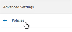
  21. On the right, in the Advanced Settings column, click Policies.
  22. Click the plus icon in the top right of the Policies box.
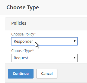
  23. Select Responder and click Continue.
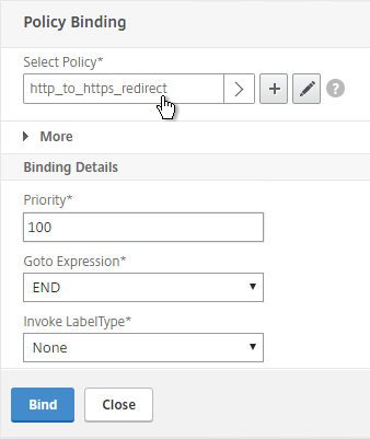
  24. Select the http_to_https Redirect Responder policy and click Bind. Then click Done.

    add lb vserver MyvServer-HTTP-SSLRedirect HTTP 10.2.2.201 80
    
    bind lb vserver storefront.corp.com-HTTP-SSLRedirect AlwaysUp
    
    bind lb vserver storefront.corp.com-HTTP-SSLRedirect -policyName http_to_ssl_redirect_responderpol -priority 100 -gotoPriorityExpression END -type REQUEST
  25. The primary advantage of this method is that the Redirect Virtual Server is UP.

NetScaler 11.1 Certificates

Last Modified: Nov 6, 2020 @ 7:23 am

Navigation

💡 = Recently Updated

Convert .PFX Certificate to PEM Format

You can export a certificate from Windows and import it to NetScaler.

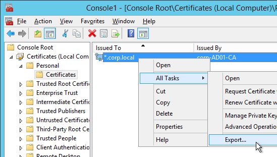
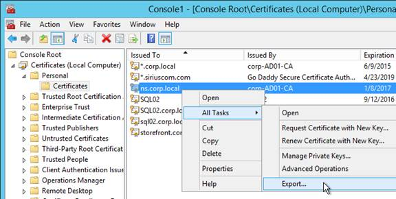
  1. On the Windows server that has the certificate, run mmc.exe and add the certificates snap-in.
  2. Right-click the certificate and click Export.
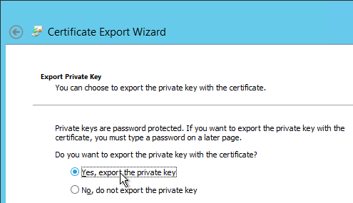
  3. On the Export Private Key page, select Yes, export the private key and click Next.
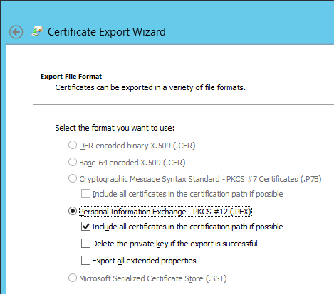
  4. On the Export File Format page, ensure Personal Information Exchange is selected and click Next.
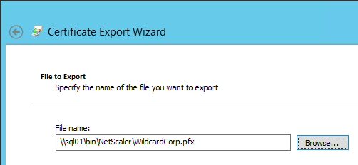
  5. Save it as a .pfx file. Don’t put any spaces in the filename.
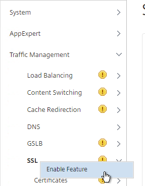
  6. Go to Traffic Management > SSL. If the SSL feature is disabled, right-click it and click Enable Feature.
  7. In NetScaler 11.1, it is no longer necessary to first convert the .PFX file to PEM format since NetScaler will convert it for you automatically. Note: when the PFX is automatically converted to PEM, the key is not encrypted.
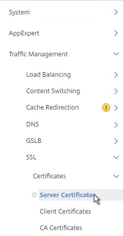
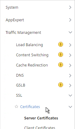
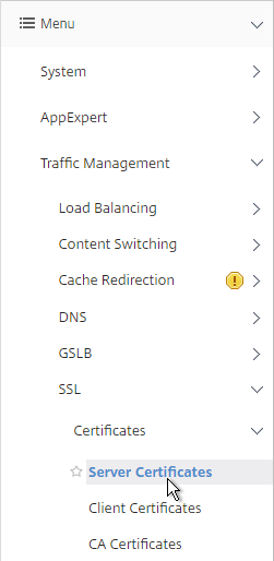
  8. Go to Traffic Management > SSL > Certificates.
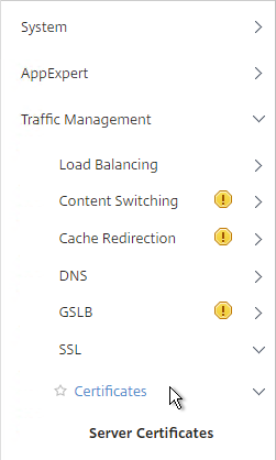
  9. There are now three different certificate nodes. Server Certificates have private keys. These certificates are intended to be bound to SSL vServers.
  10. Client Certificates also have private keys but they are intended to be bound to Services so NetScaler can perform client-certificate authentication against back-end web servers.
  11. CA Certificates don’t have private keys. These certificates can authenticate client certificates. Or you can link Server Certificates to CA Certificates to create a trust chain.
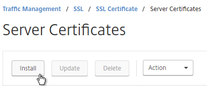
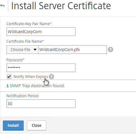
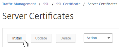
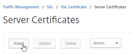
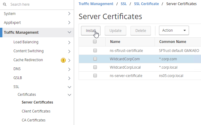
  12. On the left, click Server Certificates. On the right, click Install.
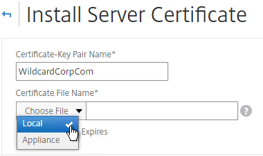
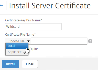
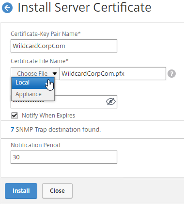
  13. Browse (Local) to the PFX file.
  14. Enter the PFX password, and then click Install.
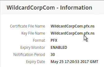
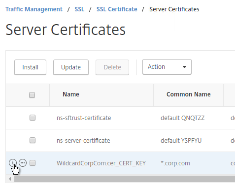
  15. If you click the information icon next to the certificate, you’ll see that NetScaler created a new file with a .ns extension.

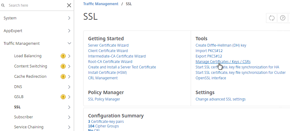
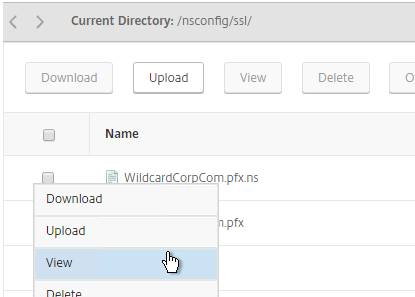
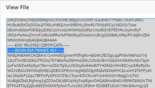
  16. If you look inside this file by going to Traffic Management > SSL > Manage Certificates / Keys / CSRs, notice that the RSA Private Key is not encrypted, encoded, or password protected.


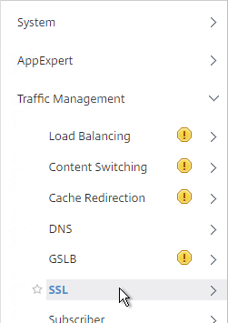
  17. If you want to encrypt your key file (recommended), use the older method of converting from PFX to PEM. In the NetScaler Configuration GUI, on the left expand Traffic Management and click SSL.
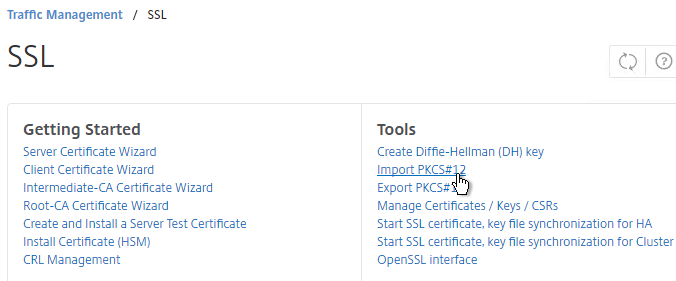
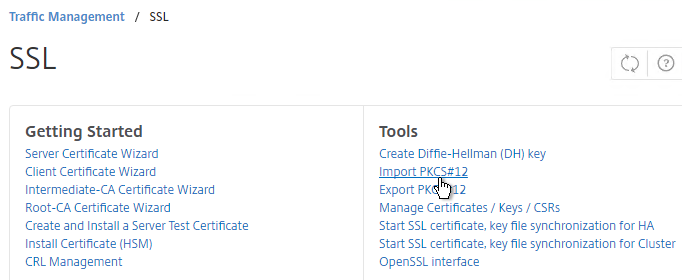
  18. In the right column of the right pane, click Import PKCS#12 in the Tools section.
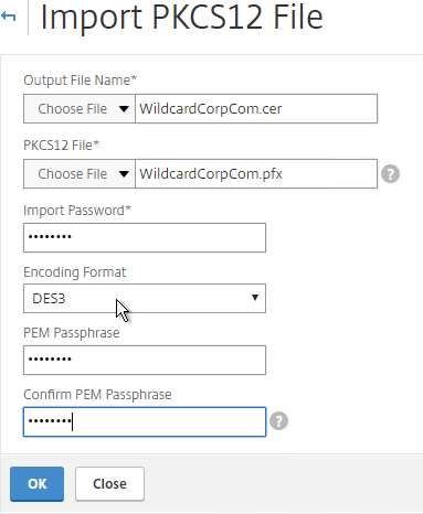
  19. In the Import PKCS12 File dialog box:
    1. In the Output File Name field, enter a name (e.g. Wildcard.cer) for a new file where the PEM certificate and key will be placed.
    2. In the PKCS12 File field, click Browse and select the previously exported .pfx file.
    3. In the Import Password field, enter the password you specified when you previously exported the .pfx file.
    4. Change the Encoding Format selection to DES3. This causes the new Output file to be encrypted.
    5. Enter a password for the Output file and click OK.
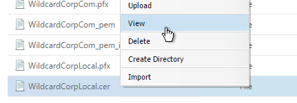
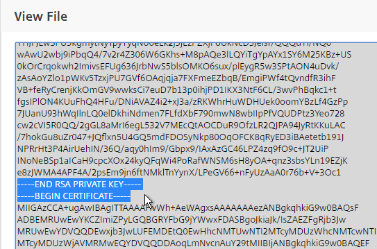
  20. If you browse to the /nsconfig/ssl directory on the NetScaler and view the new .cer file you just created, you’ll see both the certificate and the private key in the same file. You can use the Manage Certificates / Keys / CSRs link to view the files.

  21. Notice that the file contains both the certificate and the RSA Private key.
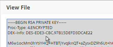
  22. Also, the Private Key is encrypted.
  23. On the left side of the NetScaler Configuration GUI, expand Traffic Management > SSL, and click Certificates.
  24. On the right, click Install.
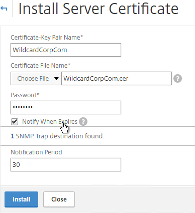
  25. In the Install Certificate dialog box:
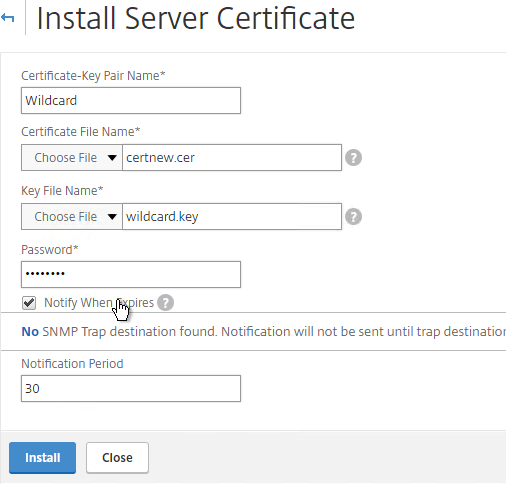
    1. In the Certificate-Key Pair Name field, enter a friendly name for this certificate.
    2. In the Certificate File Name field, browse the appliance and select the .cer file you just created.
    3. If the private key is encrypted, enter the password.
    4. If desired, check the box next to Notify When Expires.
    5. Click Install. You can now link an intermediate certificate to this SSL certificate and then bind this SSL certificate to SSL  and/or NetScaler Gateway Virtual Servers.
  26. To automatically backup SSL certificates and receive notification when the certificates are about the expire, deploy Citrix Command Center or NetScaler Management and Analytics System. Also see Citrix CTX213342 How to handle certificate expiry on NetScaler.
  27. You can also export the certificate files and use them on a different NetScaler.

Create Key and Certificate Request

If you want to create free Let’s Encrypt certificates, see John Billekens’ PowerShell script detailed at Let’s Encrypt Certificates on a NetScaler.  💡

You can create a key pair and Certificate Signing Request directly on the NetScaler appliance. The Certificate Signing Request can then be signed by an internal or public Certificate Authority.

Most Certificate Authorities let you add Subject Alternative Names when submitting the Certificate Signing Request to the Certificate Authority and thus there’s no reason to include Subject Alternative Names in the Certificate Signing Request. You typically create a Certificate Signing Request with a single DNS name. Then when submitting the Certificate Signing Request to the Certificate Authority you type in additional DNS names. For a Microsoft Certificate Authority, you can enter Subject Alternative Names in the Attributes box of the Web Enrollment wizard. For public Certificate Authorities, you purchase a UCC certificate or purchase a certificate option that lets you type in additional names.

If you instead want to create a Certificate Signing Request on NetScaler that has Subject Alternative Names embedded in it as request attributes, see Citrix Blog Post How to Create a CSR for a SAN Certificate Using OpenSSL on a NetScaler Appliance. These instructions are performed on the NetScaler command line using OpenSSL. Or you can instead create a Subject Alternative Name certificate on Windows.

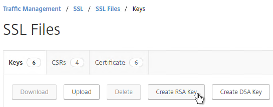
  1. On the left, expand Traffic Management, expand SSL, and click SSL Files.
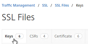
  2. On the right, switch to the Keys tab.
  3. Click Create RSA Key.
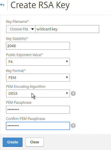
  4. Give the .key file a descriptive name.
  5. Set the Key Size to 2048 bits
  6. Set the PEM Encoding Algorithm to DES3 and enter a password. This encrypts the key file.
  7. Click OK. You will soon create a certificate using the keys in this file.
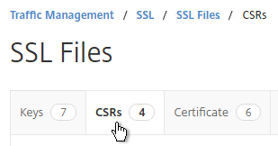
  8. On the right, switch to the CSRs tab.
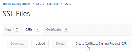
  9. Click Create Certificate Signing Request (CSR).
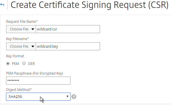
  10. In the Request File Name field, enter the name of a new file.
  11. In the Key Filename field, browse to the previously created .key file.
  12. If the key file is encrypted, enter the password.
  13. Feel free to change the Digest Method to SHA256.
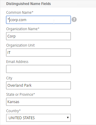
  14. In the Common Name field, enter the FQDN of the SSL enabled-website. If this is a wildcard certificate, enter * for the left part of the FQDN.
  15. In the Organization Name field, enter your official Organization Name.
  16. Enter IT or similar as the Organization Unit.
  17. Enter the City name.
  18. In the State field, enter your state name without abbreviating.
  19. Scroll down and click Create.
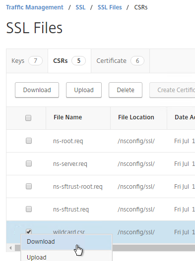
  20. Click the ellipsis next to the new .csr file and Download the file.

  21. You can then open the .csr file with Notepad and send the contents to your Certificate Authority. If the CA asks you for the type of web server, select Apache. Save the CA response as a Base64 file.
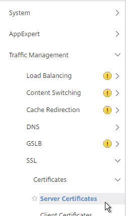
  22. After you get the signed certificate, on the left side of the NetScaler Configuration GUI, expand Traffic Management > SSL > Certificates and click Server Certificates.
  23. On the right, click Install.
  24. In the Certificate-Key Pair Name field, enter a friendly name for this certificate.
  25. In the Certificate File Name field, browse Local and select the Base64 (Apache) .cer file you received from the Certificate Authority.
  26. In the Private Key File Name field, browse the appliance and select the key file you created earlier.
  27. If the key file is encrypted, enter the password.
  28. If desired, check the box next to Notify When Expires.
  29. Click Install.
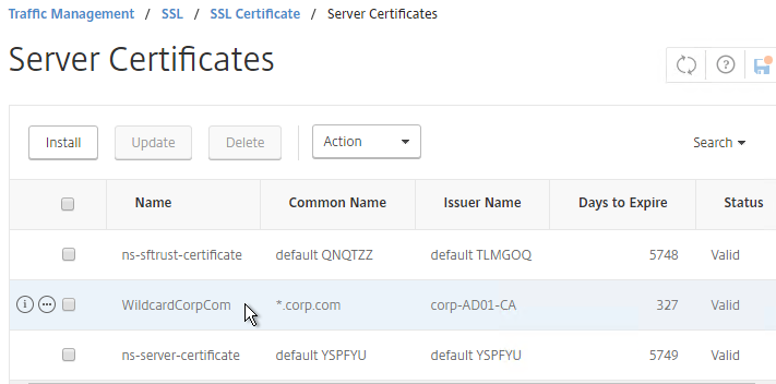
  30. The certificate is now added to the list. Notice the Days to Expire. You can now bind this certificate to any SSL Load Balancing, NetScaler Gateway, or SSL Content Switching Virtual Server.
  31. To automatically backup SSL certificates and receive notification when the certificates are about the expire, deploy Citrix Command Center or Citrix NetScaler Management and Analytics. Also see Citrix CTX213342 How to handle certificate expiry on NetScaler.
  32. You can also export the certificate files and use them on a different NetScaler.

Intermediate Certificate

If your Server Certificate is signed by an intermediate Certificate Authority, then you must install the intermediate Certificate Authority’s certificate on the NetScaler. This Intermediate Certificate then must be linked to the Server Certificate.

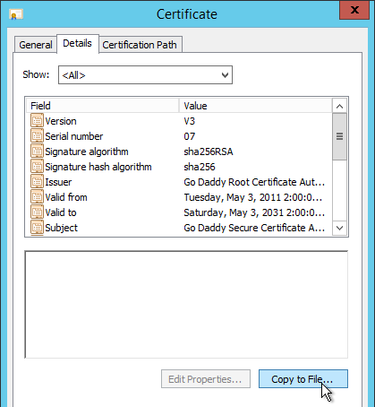
  1. Sometimes the public Certificate Authority will give you the Intermediate certificate as one of the files in a bundle. If not, log into Windows and double-click the signed certificate.
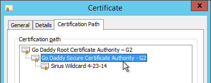
  2. On the Certification Path tab, double-click the intermediate certificate (e.g. Go Daddy Secure Certificate Authority. It’s the one in the middle).
  3. On the Details tab, click Copy to File.
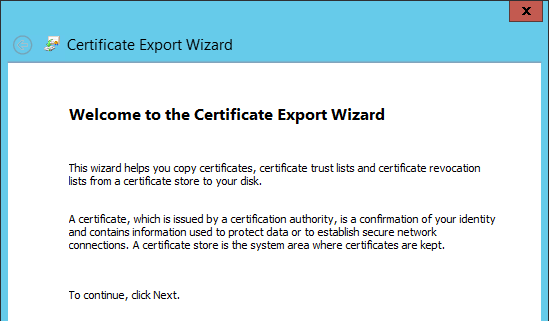
  4. In the Welcome to the Certificate Export Wizard page, click Next.
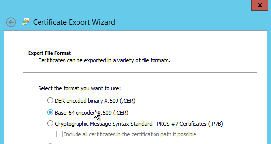
  5. In the Export File Format page, select Base-64 encoded and click Next.
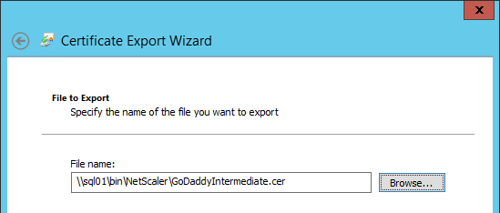
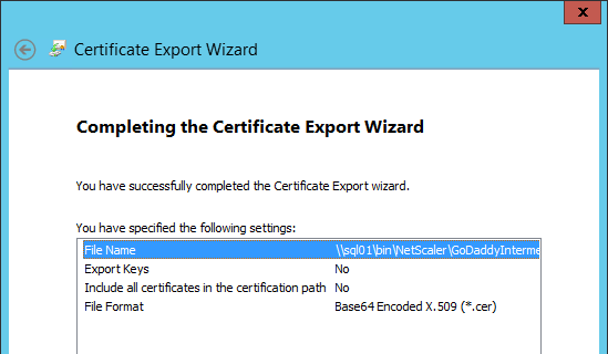
  6. Give it a file name and click Next.
  7. In the Completing the Certificate Export Wizard page, click Finish.
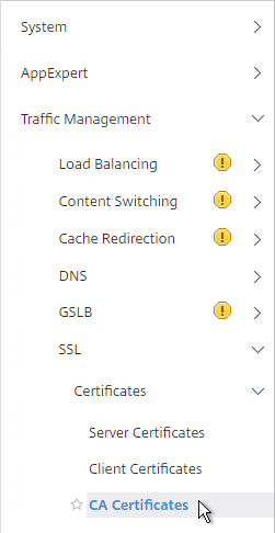
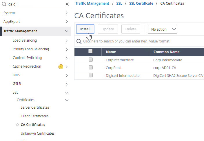
  8. In the NetScaler configuration GUI, expand Traffic Management, expand SSL, expand Certificates, and click CA Certificates.
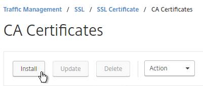
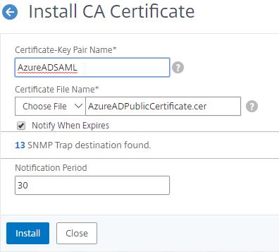
  9. On the right, click Install.
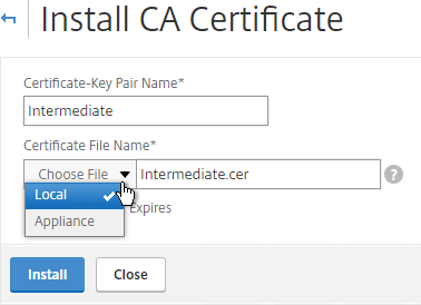
  10. Name it Intermediate or similar.
  11. Browse locally for the Intermediate certificate file.
  12. Click Install.
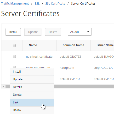
  13. Go back to Server Certificates.
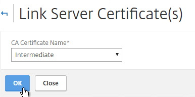
  14. Click the ellipsis next to the server certificate, and click Link.
  15. The previously imported Intermediate certificate should already be selected. Click OK.

Export Certificate Files from NetScaler

You can easily export certificate files from the NetScaler and import them to a different NetScaler.

  1. Go to Traffic Management > SSL > Certificates > Server Certificates.
  2. Move your mouse over the certificate you want to export, and then click the information icon on the far left.
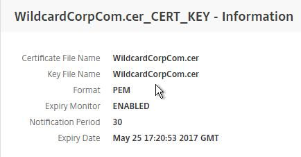
  3. Note the file names. There could be one or two file names.
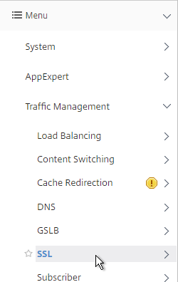
  4. Go to Traffic Management > SSL.
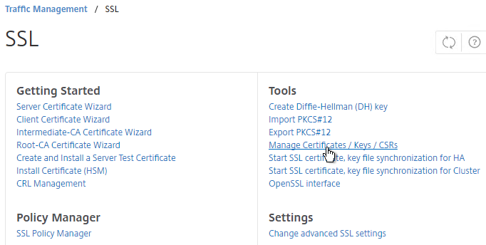
  5. On the right, in the right column, click Manage Certificates / Keys / CSRs.
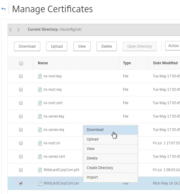
  6. Find the file(s) in the list, right-click it, and click Download.
  7. Also download the files for any linked intermediate certificate.
  8. You can now use the downloaded files to install certificates on a different NetScaler.

Create Certificate with NetScaler as Certificate Authority

If you don’t have an internal Certificate Authority, you can use NetScaler as a Certificate Authority. The NetScaler Certificate Authority can then be used to sign Server Certificates. This is a simple method for creating a new management certificate. The main problem with this method is that the NetScaler root certificate must be manually installed on any machine that connects to the NetScaler.

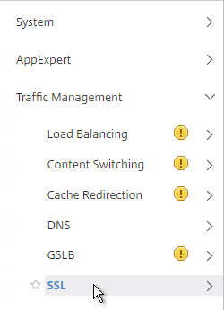
  1. On the left, expand Traffic Management, and click SSL.
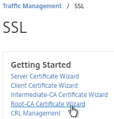
  2. On the right, in the left column, click Root-CA Certificate Wizard.
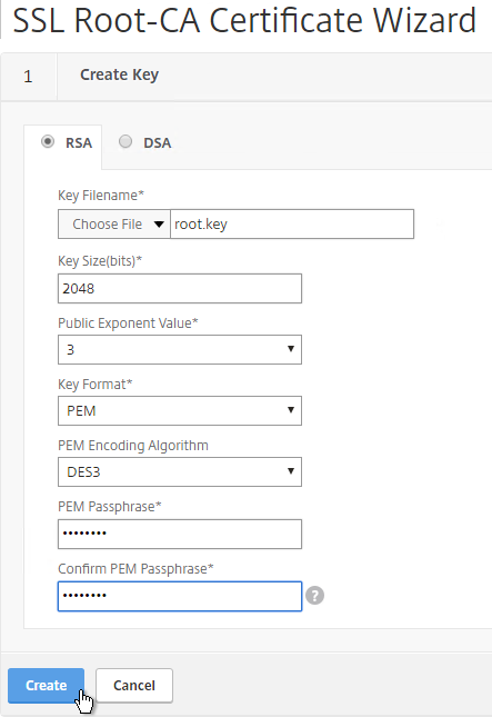
  3. In the Key Filename field, enter root.key or similar. This is a new file.
  4. In the Key Size field, enter at least 2048.
  5. Optionally, to encrypt the key file, change the PEM Encoding Algorithm to DES3, and enter a new password.
  6. Click Create.
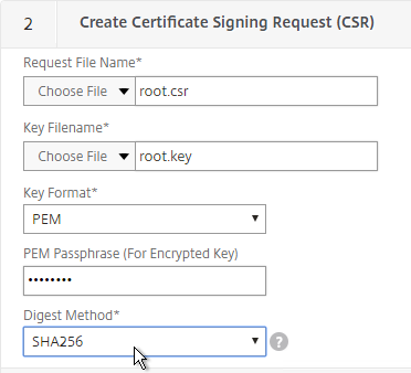
  7. In the Request File Name field, enter root.csr or similar. This is a new file.
  8. If the key file is encrypted, enter the password.
  9. Scroll down.
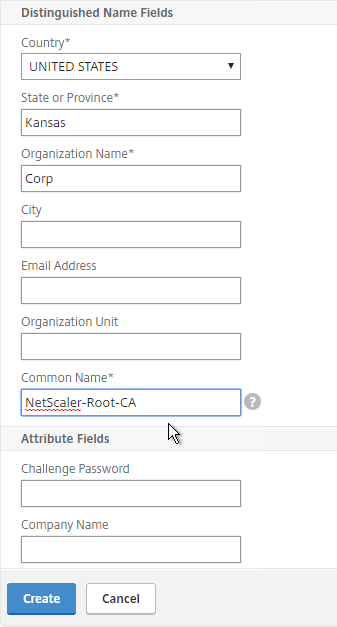
  10. In the State field, enter the non-abbreviated state name.
  11. In the Organization Name field, enter the name of your organization.
  12. Fill in other fields as desired.
  13. In the Common Name field, enter a descriptive name for this Certificate Authority.
  14. Click Create .
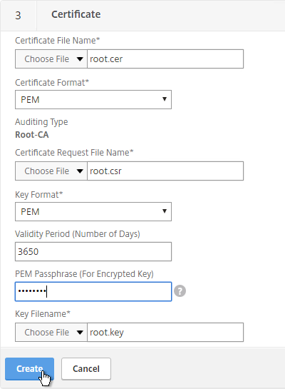
  15. In the Certificate File Name field, enter root.cer or similar. This is a new file.
  16. Change the Validity Period to 3650 (10 years) or similar.
  17. If the key file is encrypted, enter the password in the PEM Passphrase field.
  18. Click Create.
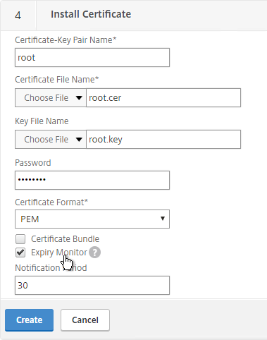
  19. In the Certificate-Key Pair Name field, enter a friendly name for this Certificate Authority certificate.
  20. If the key file is encrypted, enter the password in the Password field.
  21. Click Create.
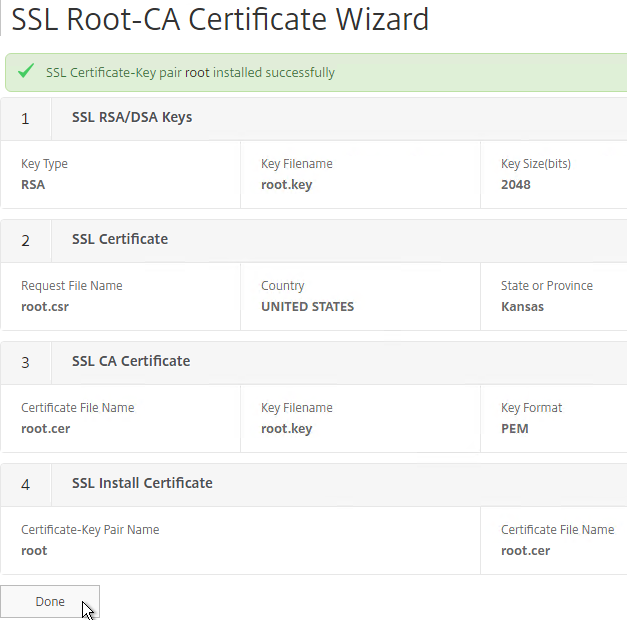
  22. Click Done.
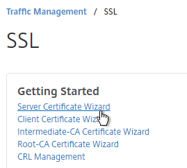
  23. In the right pane, in the left column, click Server Certificate Wizard.
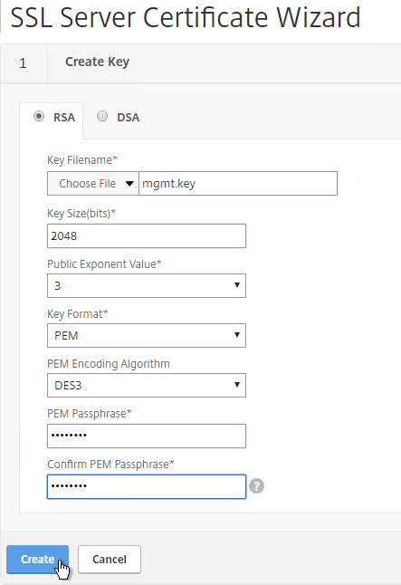
  24. In the Key Filename field, enter mgmt.key or similar. This is a new file.
  25. In the Key Size field, enter at least 2048.
  26. Optionally, to encrypt the key file, change the PEM Encoding Algorithm to DES3, and enter a new password.
  27. Click Create.
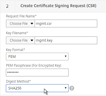
  28. In the Request File Name field, enter mgmt.csr or similar. This is a new file.
  29. If the key file is encrypted, enter the password.
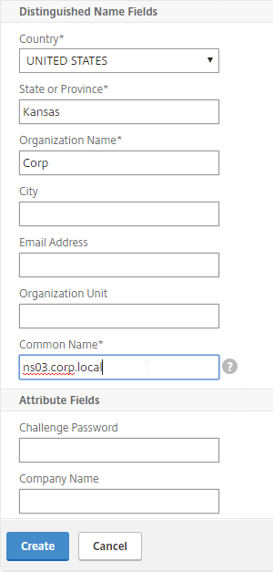
  30. Scroll down.
  31. In the State field, enter the non-abbreviated state name.
  32. In the Organization Name field, enter the name of your organization.
  33. Fill in other fields as desired.
  34. In the Common Name field, enter the hostname (FQDN) of the appliance.
  35. Click Create.
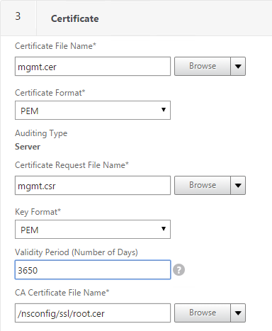
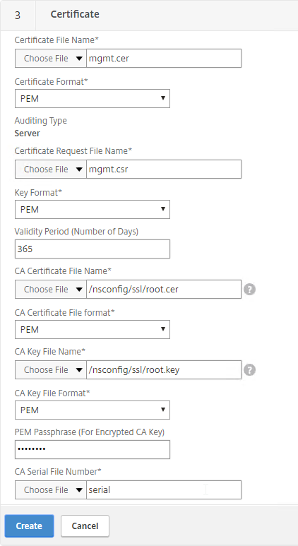
  36. In the Certificate File Name field, enter mgmt.cer or similar. This is a new file.
  37. Change the Validity Period to 3650 (10 years) or similar.
  38. Scroll down.
  39. In the CA Certificate File Name field, browse to the root.cer file.
  40. In the CA Key File Name field, browse to the root.key file.
  41. If the key file is encrypted, enter the password.
  42. In the CA Serial File Number field, enter the name of a new file that will contain serial numbers.
  43. Click Create.
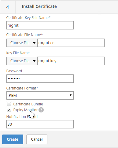
  44. In the Certificate-Key Pair Name field, enter a friendly name for this management certificate.
  45. If the key file is encrypted, enter the password in the Password field.
  46. Click Create.
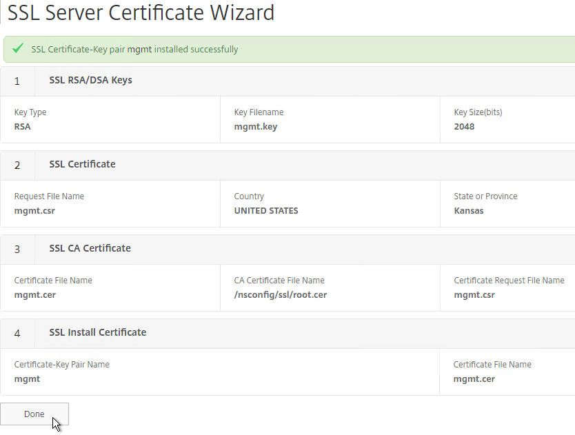
  47.  Click Done.

Default Management Certificate Key Length

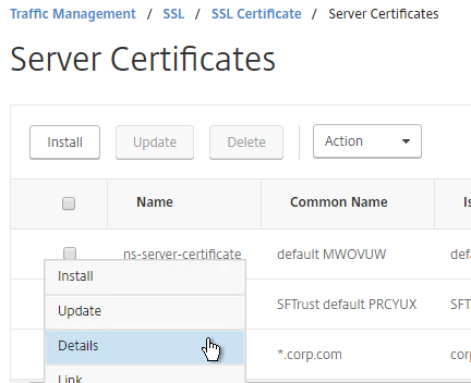
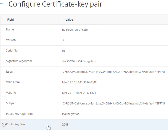
In older NetScaler builds, the default management certificate (ns-server-certificate) key size is only 512 bits. To see the key size, click the ellipsis next to ns-server-certificate and then click Details.


If you try to use Internet Explorer to connect to the NSIP using SSL, Internet Explorer will consider 512 bits to be unsafe and probably won’t let you connect. Notice there’s no option to proceed.

You can configure Internet Explorer to accept the 512-bit certificate by running Certutil ‑setreg chain\minRSAPubKeyBitLength 512 on the same machine where Internet Explorer is running.

When you upgrade to 11.1, the management certificate remains at whatever was installed previously. If it was never replaced, then the management certificate is still only 512 bits. To replace the certificate with a new 2048-bit self-signed certificate, simply delete the existing ns-server-certificate certificate files and reboot.

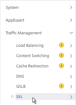
  1. Go to Traffic Management > SSL.
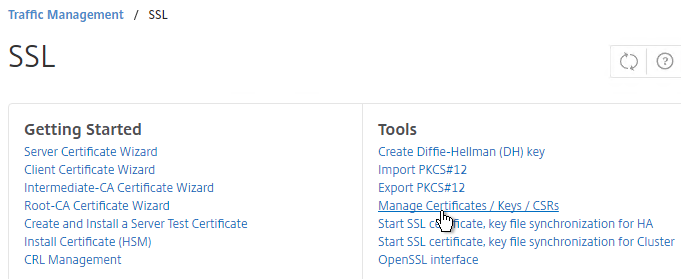
  2. On the right, in the right column, click Manage Certificates / Keys / CSRs.
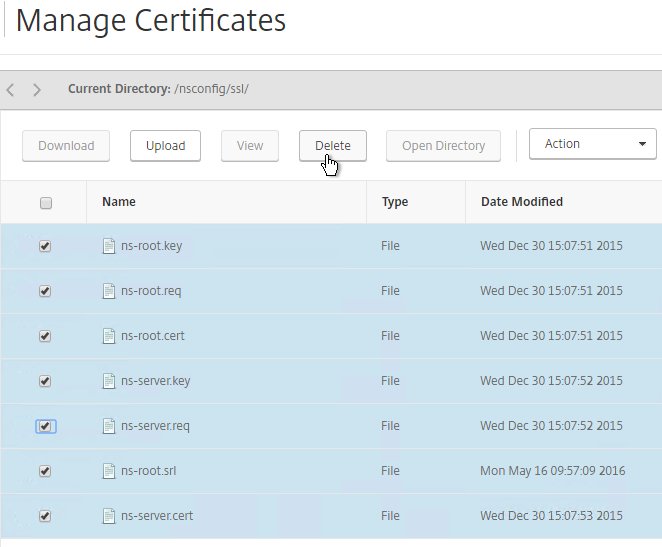
  3. Highlight any file named ns-* and delete them. This takes several seconds.
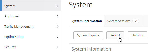
  4. Then go to System and reboot.
  5. After a reboot, if you view the Details on the ns-server-certificate, it will be recreated as self-signed with 2048-bit key size.

Replace Management Certificate

You can replace the default management certificate with a new trusted management certificate.

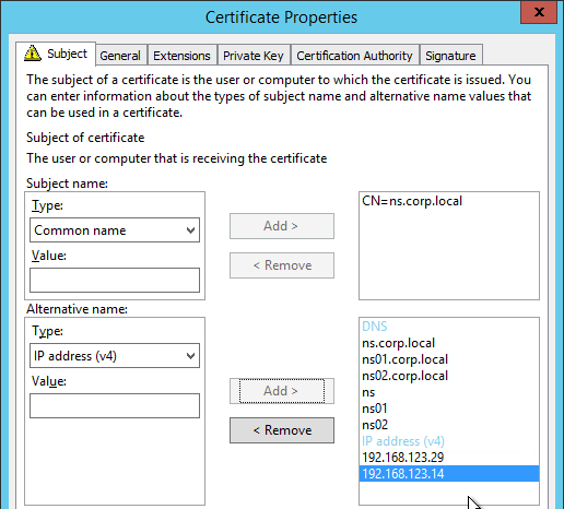
Only one certificate will be loaded on both nodes in a High Availability pair so make sure the management certificate matches the names of both nodes. This is easily doable using a Subject Alternative Name certificate. Here are some names the management certificate should match (note: a wildcard certificate won’t match all of these names):

  • The FQDN for each node NSIP in a High Availability pair. Example: ns01.corp.local and ns02.corp.local
  • The shortnames (left label) for each node NSIP in a High Availability pair. Example: ns01 and ns02
  • The NSIP IP address for each node in a High Availability pair. Example: 192.168.123.14 and 192.168.123.29
  • If you enabled management access on your SNIPs, add names for the SNIPs:
    • FQDN for the SNIP. Example: ns.corp.local
    • Shortname for the SNIP. Example: ns
    • SNIP IP address. Example: 192.168.123.30

If you are creating a Subject Alternative Name certificate, it’s probably easiest to do the following:

  1. Create the certificate using the Certificates snap-in on a Windows box. You can add the Subject Alternative Names in the certificate request wizard. The Subject Alternative Names for the IP addresses must be added as IP address (v4). The other Subject Alternative Names are added as DNS.
  2. Export the certificate and Private Key to a .pfx file.
  3. On the NetScaler, use the Import PKCS#12 tool to convert the .pfx to PEM format. Then follow one of the procedures below to replace the management certificate.

There are two methods of replacing the management certificate:

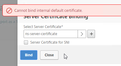
  • Use the Update Certificate button for ns-server-certificate in the NetScaler GUI. This automatically updates all of the Internal Services bindings too.
    • You cannot rename the certificate in the NetScaler GUI. It remains as ns-server-certificate.
    • ns-server-certificate cannot be bound to Virtual Servers. So make sure it is a dedicated management certificate.
  • Or manually Bind a new certificate to the Internal Services.

Update Certificate Method

The Update Certificate button method is detailed below:

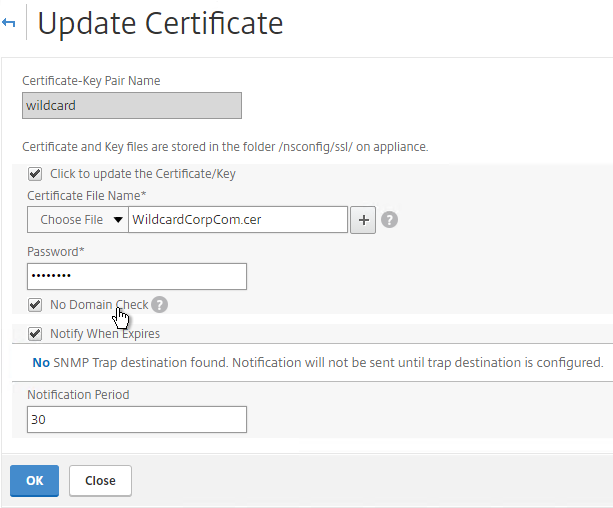
  1. You can’t update the certificate while connected to the NetScaler using https so make sure you connect using http.
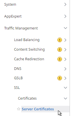
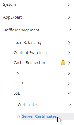
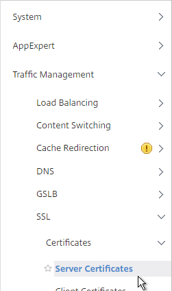
  2. On the left, expand Traffic Management, expand SSL expand Certificates, and click Server Certificates.
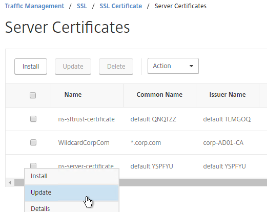
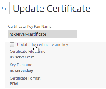
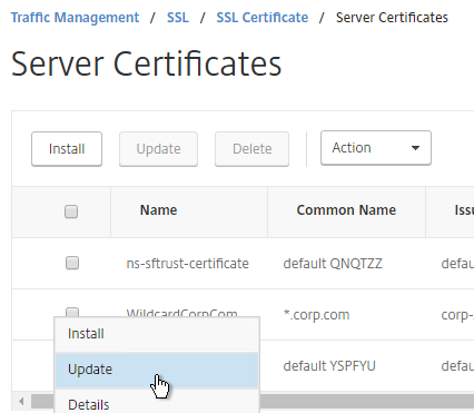
  3. On the right, click the ellipsis next to ns-server-certificate and click Update.
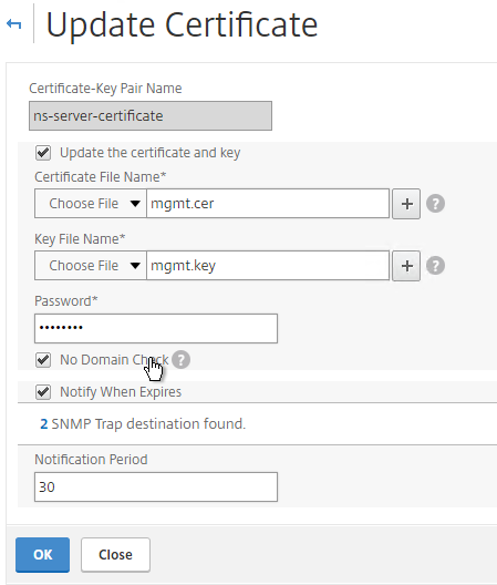
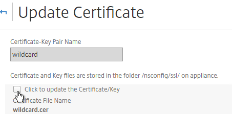
  4. Check the box next to Click to update the certificate and key.
  5. Browse to the new management certificate. It could be on the appliance or it could be on your local machine.
  6. If the PEM certificate is encrypted, enter the password.
  7. Check the box next to No Domain Check. Click OK.
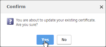
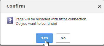
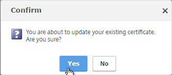
  8. Click Yes to update the certificate.
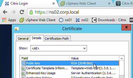
  9. You can now connect to the NetScaler using https protocol. The certificate should be valid and it should have a 2048 bit key.
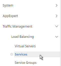
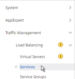
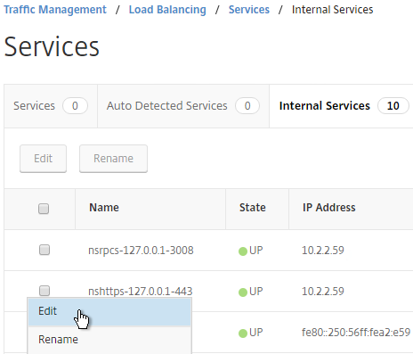
  10. Go to Traffic Management > Load Balancing > Services.
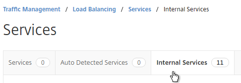
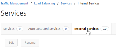
  11. On the right, switch to the Internal Services tab.
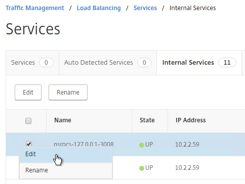
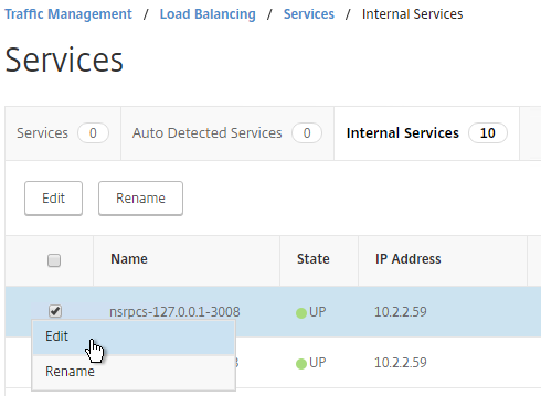
  12. Click the ellipsis next to one of the services and click Edit.
  13. Scroll down to the SSL Ciphers section. Feel free to change the ciphers to a more secure cipher group. NetScaler 11.1 no longer includes RC4 ciphers in the DEFAULT cipher group, but you might want to rearrange the ciphers.
  14. Repeat this for each of the Internal Services.

Manual Binding Method

The manual Binding to Internal Services method is detailed below:

  1. You can’t update the certificate while connected to the NetScaler using https so make sure you connect using http.
  2. On the left, expand Traffic Management, expand SSL, expand Certificates, and click Server Certificates.
  3. On the right, use the Install button to install the new management certificate.
  4. On the left, expand Traffic Management, expand Load Balancing, and click Services.
  5. On the right, switch to the Internal Services tab.
  6. You will see multiple services. Edit one of them.
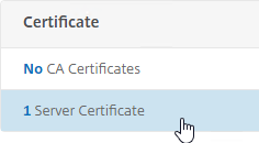
  7. Scroll down and click where it says 1 Server Certificate.
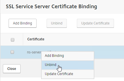
  8. Select the existing management certificate, and click Unbind.
  9. Click Yes to remove the selected entity.
  10. Click Add Binding.
  11. Click where it says Click to select.
  12. Select the new management certificate, and click Select.
  13. Click Bind, and click Close.
  14. Scroll to the SSL Parameters section, and click the pencil icon.
  15. Uncheck the box next to SSLv3. Make sure TLSv11 and TLSv12 are enabled. Click OK.
  16. On the left, in the SSL Ciphers section, click the pencil icon.
  17. Select a more secure Cipher Group. NetScaler 11.1 no longer includes RC4 in the DEFAULT cipher group, but the ciphers could be reordered in a more secure order.
  18. Repeat for the rest of the internal services.

Force Management SSL

By default, administrators can connect to the NSIP using HTTP or SSL. This section details how to disable HTTP.

  1. Connect to the NSIP using https.
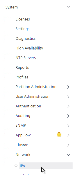
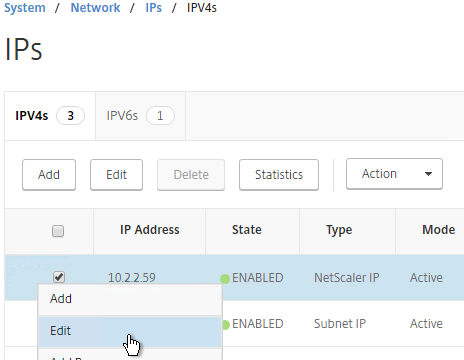
  2. On the left, expand System, expand Network, and click IPs.
  3. On the right, select your NetScaler IP, and click Edit.
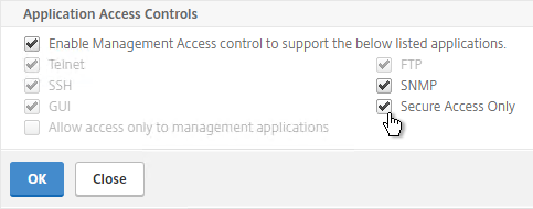
  4. Near the bottom, check the box next to Secure access only, and then click OK.
  5. If you are connected using http, the page will reload using https.

    set ns ip 10.2.2.126 -gui SECUREONLY
  6. Citrix CTX204217 How to redirect users from HTTP to HTTPS while accessing NSIP/Management IP. Requires a Responder policy, and a nsapimgr command.
  7. Repeat this on the secondary appliance.
  8. Repeat for any SNIPs that have management access enabled.

SSL Certificate – Update

If your certificate is about to expire, do the following:

  1. Create updated certificate files in PEM format. One option is to create a key file and Certificate Signing Request directly on the NetScaler. Another option is to convert a PFX file to a PEM file. Don’t install the certificate yet, but instead, simply have access to the key file and certificate file in PEM format.
  2. In NetScaler, navigate to Traffic Management > SSL > Certificates > Server Certificates.
  3. On the right, click the ellipsis next to the certificate you intend to update, and click Update.
  4. Check the box next to Click to update the Certificate/Key.
  5. Browse to the updated certificate and key files. If the private key is encrypted, specify the password.
  6. Click Yes to update the certificate.
  7. Click OK. This will automatically update every Virtual Server on which this certificate is bound.
  8. Certificates can also be updated in Citrix Command Center or NetScaler Management and Analytics System.

Global Server Load Balancing (GSLB) – NetScaler 11.1

Last Modified: Nov 7, 2020 @ 6:34 am

Navigation

💡 = Recently Updated

GSLB Planning

GSLB is nothing more than DNS. GSLB is not in the data path. GSLB receives a DNS query, and GSLB sends back an IP address, which is exactly how a DNS server works. The user then connects to the returned IP, which doesn’t even need to be on a NetScaler.

GSLB can do some things that DNS servers can’t do:

  • Don’t give out an IP address unless it is UP (monitoring)
    • If the active IP address is down, then give out the passive IP address (active/passive)
  • Give out the IP address that is closest to the user (proximity load balancing)
  • Give out different IPs for internal users vs external users (DNS View)

GSLB is only useful if you have a single DNS name that could resolve to two or more IP addresses. If there’s only one IP address, then use normal DNS instead.

Citrix Blog Post Global Server Load Balancing: Part 1 explains how DNS queries work and how GSLB fits in.

Citrix has a good DNS and GSLB Primer.

When configuring GSLB, don’t forget to ask “where is the data?”. For XenApp/XenDesktop, DFS multi-master replication of user profiles is not supported, so configure “home” sites for users. More information at Citrix Blog Post XenDesktop, GSLB & DR – Everything you think you know is probably wrong!

GSLB Configuration Overview

GSLB Configuration can be split between one-time steps for GSLB infrastructure, and repeatable steps for each GSLB-enabled DNS name.

One-time GSLB Infrastructure configuration

  1. Create ADNS listener on each NetScaler pair – DNS clients send DNS queries to the ADNS listeners. GSLB resolves a DNS query into an IP address, and returns the IP address in the DNS response.
  2. Create GSLB Sites (aka MEP Listener) – GSLB Sites usually correspond to different datacenters. GSLB Sites are also the IP address endpoints for NetScaler’s proprietary Metric Exchange Protocol (MEP), which is used by GSLB to transmit proximity, persistence, and monitoring information.
  3. Import Static Proximity Database – NetScaler includes a database that can be used to determine the geographical location of an IP address. Or you can subscribe to a geolocation service, and import its database.
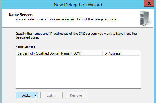
  4. Delegate DNS sub-zone to NetScaler ADNS – in the original DNS zone, create a new sub-zone (e.g. gslb.company.com), and delegate the sub-zone to all ADNS listeners.

Repeatable GSLB Configuration for each DNS name:

  1. Create one or more GSLB Services per DNS name, and per IP address response – each GSLB Service corresponds to a single IP address that can be returned in response to a DNS Query.
    • Optionally, bind a Monitor to each GSLB Service. Monitors determine if the GSLB Service is up or not.
  2. Create a GSLB Virtual Server per DNS name
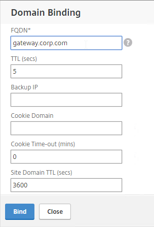
    • Bind a DNS name to the GSLB Virtual Server.
    • For active/active – bind multiple GSLB Services to the GSLB Virtual Server, configure a load balancing method (e.g. proximity), and configure site persistence.
    • For active/passive – bind the active GSLB Service. Create another GSLB Virtual Server with passive GSLB Service, and configure as Backup Virtual Server.
  3. Create CNAME records for each delegated DNS name – in the main DNS zone, create a CNAME that maps the original DNS name to the delegated sub-zone. For example, CNAME citrix.company.com to citrix.gslb.company.com.

You will create separate GSLB Services, separate GSLB Virtual Servers, and separate CNAMEs for each DNS name. If you have a bunch of DNS names that you want to GSLB-enable, then you’ll repeat these steps for each GSLB-enabled DNS name.

Each datacenter has a separate ADNS listener IP address. DNS is delegated to all GSLB ADNS Listener IPs, and any one of them can respond to the DNS query. Thus, all NetScaler pairs participating in GSLB should have the same Per-DNS name configuration.

One NetScaler appliance for both public DNS/GSLB and internal DNS/GSLB?

GSLB can be enabled both publically and internally. For public GSLB, configure it on DMZ NetScaler appliances, and expose the DNS listener to the Internet. For internal GSLB, configure it on separate internal NetScaler appliances/instances, and create an internal DNS listener.

Each NetScaler appliance only has one DNS table, so if you try to use the same NetScaler for both public DNS and internal DNS, then be aware that external users can query for internal GSLB-enabled DNS names. As described by Phil Bossman in the comments, you can use a Responder policy to prevent external users from reading internal DNS names.

add policy patset GSLB_INTERNAL
bind policy patset GSLB_INTERNAL internalHostname.gslb.domain.com -index 1
add responder action DNS_Empty_Response respondwith DNS.NEW_RESPONSE
add responder policy GSLB_DNS_Empty_Response "(!(CLIENT.IP.SRC.IN_SUBNET(10.0.0.0/8)||CLIENT.IP.SRC.IN_SUBNET(192.0.0.0/16)||CLIENT.IP.SRC.IN_SUBNET(172.0.0.0/12)) && DNS.REQ.QUESTION.DOMAIN.CONTAINS_ANY(\"GSLB_INTERNAL\"))" DNS_Empty_Response
bind responder global GSLB_DNS_Empty_Response 100 END -type DNS_REQ_DEFAULT

One appliance resolving a single DNS name differently for internal and public

Let’s say you have a single DNS name citrix.company.com. When somebody external resolves the name, it should resolve to a public IP. When somebody internal resolves the name, it should resolve to an internal IP.

For internal GSLB and external GSLB of the same DNS name on the same NetScaler appliance, you can use DNS Policies and DNS Views to return different IP addresses depending on where users are connecting from. See Citrix CTX130163 How to Configure a GSLB Setup for Internal and External Users Using the Same Host Name.

If the Internet circuit in the remote datacenter goes down, then this should affect public DNS, since you don’t want to give out a public IP that isn’t reachable. But do you also want an Internet outage to affect internal DNS? Probably not. In that case, you would need different GSLB monitoring configurations for internal DNS and external DNS. However, if you have only a single GSLB Virtual Server with DNS Views, then you can’t configure different monitoring configurations for each DNS View.

To work around this limitation, create two separate GSLB Virtual Servers with different monitoring configurations. Internal DNS uses a CNAME record to reach the GSLB Virtual Server configured for internal monitoring:

  • External citrix.company.com:
    • Configure NetScaler GSLB for citrix.company.com.
    • On public DNS, delegate citrix.company.com to the NetScaler DMZ ADNS services.
  • Internal citrix.company.com:
    • Configure NetScaler GSLB for citrixinternal.company.com or something like that.
    • On internal DNS, create CNAME for citrix.company.com to citrixinternal.company.com
    • On internal DNS, delegate citrixinternal.company.com to NetScaler internal ADNS services.

Remote Internet Monitoring

For public DNS/GSLB, you don’t want to give out a remote public IP address if that remote public IP address is not reachable. That means the local NetScaler will need to somehow determine if the remote datacenter has Internet connectivity or not. Here are some methods of verifying the remote Internet connection:

  • Route GSLB Metric Exchange Protocol (MEP) across the Internet. If MEP goes down, then all IP addresses associated with the remote GSLB Site are assumed to be down, and thus the local NetScaler will stop giving out those remote IP addresses.
  • Bind explicit monitors to each GSLB Service, and ensure the monitoring is routed across the Internet.

GSLB IP Addresses

GSLB is separate from data traffic. The GSLB IP addresses are separate from the IP addresses needed for data.
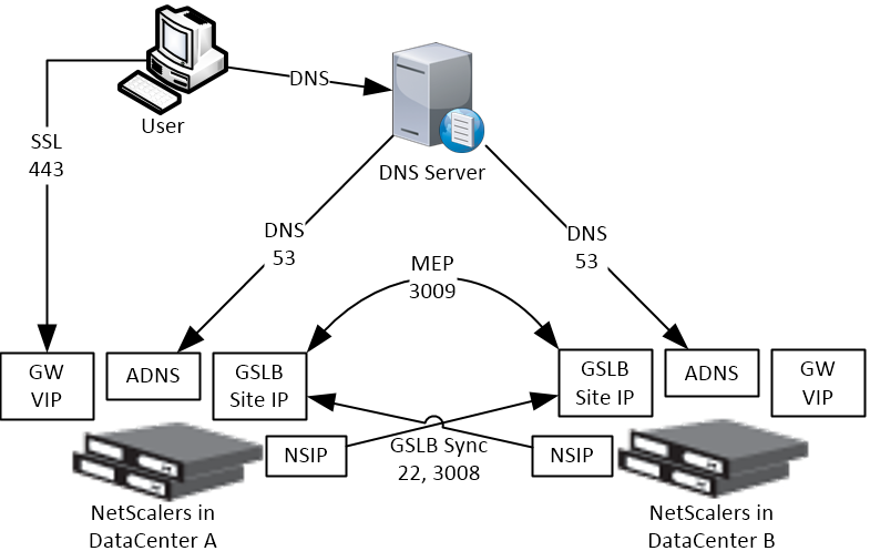
Some GSLB-specific IP Addresses are needed on each NetScaler pair:

  • ADNS Listener IP: A NetScaler IP that listens for DNS queries.
    • The ADNS listener IP is typically an existing SNIP on the appliance.
    • For external DNS, create a public IP for the ADNS Listener IP, and open UDP 53, so Internet-based DNS servers can access it.
    • A single NetScaler appliance can have multiple ADNS listeners – typically one ADNS listener for public, and another ADNS listener for internal.
  • GSLB Site IP / MEP listener IP: A NetScaler IP that will be used for NetScaler-to-NetScaler GSLB communication. This communication is called MEP or Metric Exchange Protocol. MEP transmits the following between GSLB-enabled NetScaler pairs: load balancing metrics, proximity, persistence, and monitoring.
    • GSLB Sites – On NetScaler, you create GSLB Sites. GSLB Sites are the endpoints for the MEP communication. Each NetScaler pair is configured with the MEP endpoints for the local appliance pair, and all remote appliance pairs.
    • TCP Ports – MEP uses port TCP 3009 or TCP 3011 between the NetScaler pairs. TCP 3009 is encrypted.
    • The ADNS IP address can be used as the MEP endpoint IP.
    • MEP endpoint can be any IP – The MEP endpoint IP address can be any IP address and does not need to be a SNIP or ADNS.
    • One MEP IP per appliance – there can only be one MEP endpoint IP address on each NetScaler pair.
    • Route MEP across Internet? – If you route MEP across the Internet, and if the MEP connection is interrupted, then Internet at one of the locations is probably not working. This is an easy way to determine if remote Internet is up or not. If you don’t route MEP across the Internet, then you’ll need to configure every remote-site GSLB Service with a monitor to ensure that the remote Internet is up.
      • Public IPs for MEP Enpoints – if you route MEP across the Internet, then you’ll need public IPs for each publically-accessible MEP endpoint IP address.
      • Public Port for MEP: Open port TCP 3009 between the MEP Public IPs. Make sure only the MEP IPs can access this port on the other NetScaler. Do not allow any other device on the Internet to access this port. Port 3009 is encrypted.
    • GSLB Sync Ports: To use GSLB Configuration Sync, open ports TCP 22 and TCP 3008 (secure) from the NSIP (management IP) to the remote public MEP IP. The GSLB Sync command runs a script in BSD shell and thus NSIP is always the Source IP.
  • Public IP Summary: In summary, for public GSLB, if MEP and ADNS are listening on the same IP, then you need one new public IP that is NAT’d to the DMZ IP that is used for ADNS and MEP (GSLB Site IP).
    • Each datacenter has a separate public IP.
    • DNS is delegated to all public ADNS IP listeners.

ADNS Listener

  1. At System > Network > IPs, identify a NetScaler-owned IP that you will use as the ADNS listener. This is typically a SNIP.
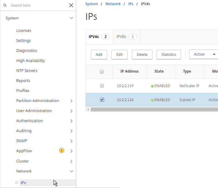
  2. Create a public IP for the ADNS Service IP, and configure firewall rules.
  3. On the left, expand Traffic Management > Load Balancing, and click Services.
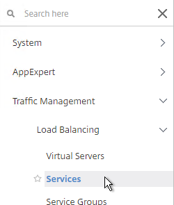
  4. On the right, click Add.
  5. In the Basic Settings section, do the following:
    1. Name the service ADNS or similar.
    2. In the IP Address field, enter an appliance SNIP.
    3. In the Protocol drop-down field, select ADNS.
  6. Click OK.
  7. Scroll down and click Done, to close the Load Balancing Service properties.
  8. On the left of the console, expand System, expand Network, and then click IPs.
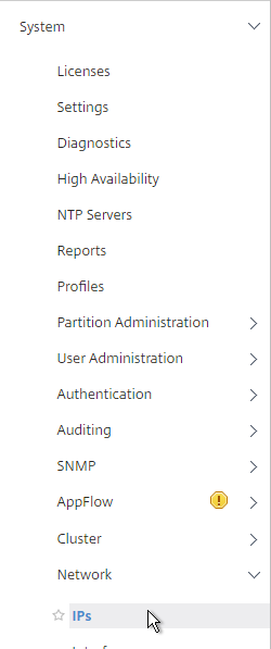
  9. On the right, you’ll see the SNIP is now marked as the ADNS svc IP.
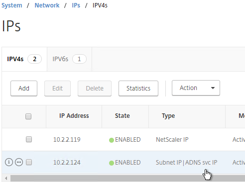
  10. Repeat ADNS configuration on the other appliance pair in the other datacenter.
  11. Your NetScaler appliances are now DNS servers.

DNS Security

  1. NetScaler 11.1 build 51 and newer includes DNS Security Options at Security > DNS Security, which can protect your ADNS service.
  2. To protect ADNS, set the Profile to All DNS Endpoints.

Metric Exchange Protocol

This section details MEP configuration between two GSLB Sites. See Citrix Docs for larger Parent-Child Topology Deployment using the MEP Protocol, including new features in NetScaler 11.1 build 51 and newer.

GSLB Sites

  1. The local GSLB Site IP can be any IP. Or you can use the same SNIP, and same public IP, used for ADNS.
  2. Open the firewall rules for Metric Exchange Protocol.
  3. On the left, expand Traffic Management, right-click GSLB, and enable the feature.
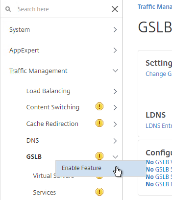
  4. Expand GSLB, and click Sites.
  5. On the right, click Add.
  6. In the Create GSLB Site page, do the following:
    1. We’re adding the local site first. Enter a descriptive name for the local site.
    2. In the Site Type drop-down, select LOCAL.
    3. In the Site IP Address field, enter an IP that this appliance will listen for MEP traffic. This is typically a DMZ SNIP.
    4. For Internet-routed GSLB MEP, in the Public IP Address field, enter the public IP that is NAT’d to the GSLB Site IP.
    5. For internal GSLB MEP, there is no need to enter anything in the Public IP field.
  7. Scroll down, and click Create, to close the Create GSLB Site page.
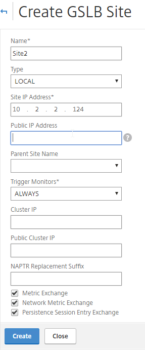
  8. Go back to System > Network > IPs, and verify that the IP is now marked as a GSLB site IP.
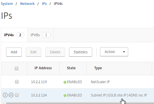
  9. If you want to use the GSLB Sync Config feature, then you’ll need to edit the GSLB site IP, and enable Management Access.

    1. Scroll down, and enable Management Access. SSH is all you need.
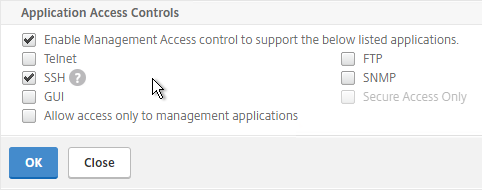
  10. Go to the other appliance pair,and also create the Local GSLB site using its GSLB site IP, and its public IP that is NAT’d to the GSLB site IP.
    1. In System > Network > IPs on the remote appliance, there should now be a GSLB site IP. This could be a SNIP. If GSLB Sync is desired, enable management access on that IP and ensure SSH is enabled.
  11. Now on each appliance add another GSLB Site, which will be the Remote GSLB site.
  12. In the Create GSLB Site page, do the following:
    1. Enter a descriptive name for the remote site.
    2. Select REMOTE as the Site Type.
    3. Enter the other appliance’s actual GSLB Site IP as configured on the appliance. This IP does not need to be reachable.
    4. In the Public IP Address field, enter the public IP that is NAT’d to the GSLB Site IP on the other appliance. For MEP, TCP 3009 must be open from the local GSLB Site IP, to the remote public Site IP. For GSLB sync, TCP 22, and TCP 3008, must be open from the local NSIP, to the remote public Site IP.
  13. Click Create.
  14. Repeat on the other appliance.

RPC

MEP defaults to unencrypted on TCP 3011. To fix that:

  1. On the left, expand System, expand Network, and click RPC.
  2. On the right, right-click the new RPC address (the other site’s GSLB Site IP), and click Edit.
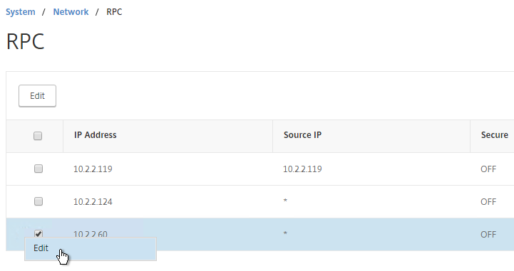
  3. On the bottom, check the box next to Secure.
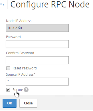
    1. If your local GSLB Site IP is not a SNIP, then you’ll need to change the RPC Node to use the local GSLB Site IP as the source IP. In the Source IP Address field, enter the local GSLB Site IP.
  4. Click OK when done.
  5. Do the same thing on the other appliance.
  6. If you go back to GSLB > Sites, you should see it as active.
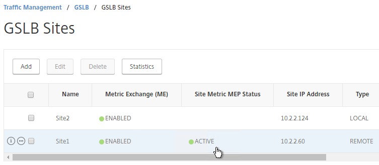
If your MEP connection between GSLB Sites flaps, it might be useful to introduce a delay before remote GSLB Services are marked as Down. In NetScaler 11.1 build 51 and newer:

  1. you can do this at Traffic Management > GSLB, on the right, in the left column, click Change GSLB settings.
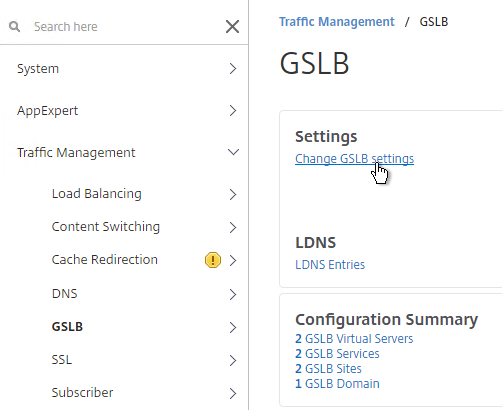
  2. In the GSLB Service State Delay Time (secs) field, enter a delay before the GSLB Services are marked as down when MEP goes down.
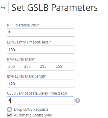
    set gslb parameter -GSLBSvcStateDelayTime 15

Static Proximity Geo Location Database

If you want to use DNS Policies or Static Proximity GSLB Load Balancing or Responders based on user’s location, import a geo location database.

NetScaler has a built-in database at /var/netscaler/inbuilt_db/ that you can use. Or you can download a database. Common free databases are:

For IP2Location, see the blog post Add IP2Location Database as NetScaler’s Location File for instructions on how to import.

Import Built-in Geo database

  1. In the NetScaler GUI, on the left, expand Traffic Management, expand GSLB, expand Location, and click Static Databases.
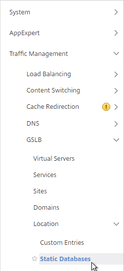
  2. On the right, click Add.
  3. Change the Import From selection to File.
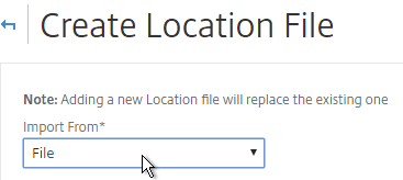
  4. Click Choose File.
  5. Browse to /var/netscaler/inbuilt_db/, and open Citrix_NetScaler_InBuilt_GeoIP_DB.csv. To browse to the directory, select var, and then click Open. Repeat for each directory until you reach /var/netscaler/inbuilt_db.
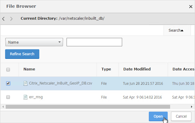
  6. In the Location Format field, if using the built-in database, select netscaler, and click Create.
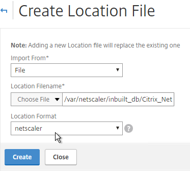
  7. When you open a GSLB Service, the public IP will be translated to a location.
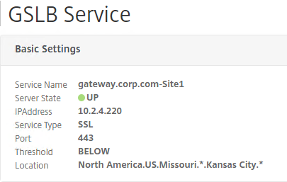
Private IP Blocks

Geo Location databases only contain entries for Public IPs. For Private IPs, do the following:

  1. On the left, expand Traffic Management, expand GSLB, expand Location, and click Custom Entries.
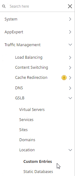
  2. On the right, click Add.
  3. Enter a range of IP addresses for a particular location.
  4. Enter a Location Name in Geo Location format, which is typically six location words separated by periods. You can look in the static proximity database for examples.
  5. Click Create.
  6. Continue creating Custom Entries for other private IP blocks.

Use Geo Locations

You can use the Geo locations in a DNS Policy, static proximity GSLB Load Balancing, or Responders:

GSLB Services

GSLB Services represent the IP addresses that are returned in DNS Responses. The IP addresses represented by GSLB Services do not need to be on a NetScaler, but NetScaler-owned IP addresses (e.g. load balancing VIPs) have additional GSLB Site Persistence options (e.g. cookie-based persistence).

  • Each potential IP address in a DNS response is a separate GSLB Service.
  • GSLB Services are associated with GSLB Sites.
  • GSLB Service configuration is identical for active/active and active/passive. GSLB Virtual Server define active/active or active/passive, not GSLB Services.

GSLB should be configured identically on all NetScaler pairs that are responding to DNS queries. Since you have no control over which NetScaler will receive the DNS query, you must ensure that both NetScaler pairs are giving out the same DNS responses.

To create a GSLB Service:

  1. On the left, expand Traffic Management > GSLB, and click Services.
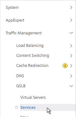
  2. On the right, click Add.
  3. The service name should be similar to the DNS name that you are trying to GSLB. Include the site name in the service name.
  4. Select one of the GSLB Sites. The IP address you’re configuring in this GSLB Service should be geographically located in the selected GSLB Site.
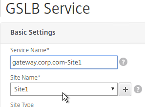
  5. On the bottom part, if the IP address is owned by this NetScaler (Local Site), then select Virtual Servers, and select a Virtual Server that is already defined on this appliance. It should automatically fill in the other fields. If you see a message asking if you wish to create a service object, click Yes. This option is only available when creating a GSLB Service in the Local GSLB Site.
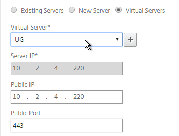
      1. If the IP address is not owned by this NetScaler, then change the selection to New Server, and enter the remote IP address in the Server IP field.
      2. The Server IP field is the IP address that NetScaler will monitor for reachability.
      3. If the remote IP is owned by a different NetScaler that is reachable by MEP, then enter the actual VIP configured on that remote NetScaler. The Server IP does not need to match what is returned to the DNS Query.
  6. In the Public IP field, enter the IP address that will be returned to the DNS Query. If you leave Public IP blank, then NetScaler will copy the Server IP to the Public IP field. For Public GSLB, the Public IP field is usually a Public IP address. For internal GSLB, the Public IP field is usually an internal IP, and probably matches the Server IP.
  7. Scroll up and make sure the Service Type is SSL. It’s annoying that NetScaler doesn’t set this drop-down correctly.
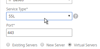
  8. Scroll down and click OK to close the Basic Settings section.
  9. GSLB Service Monitoring – on the right, in the Advanced Settings column, you can click Monitors to bind a monitor to this GSLB Service. Review the following notes before you bind a monitor.

    • Local NetScaler VIP – If the GSLB Service IP is a VIP on the local appliance, then GSLB will simply use the state of the local traffic Virtual Server (Load Balancing, Content Switching, or Gateway). There’s no need to bind a monitor to the GSLB Service.
    • Remote NetScaler VIP – If the GSLB Service IP is a VIP on a remote appliance, then GSLB will use MEP to ask the other appliance for the state of the remote traffic Virtual Server. In both cases. There’s no need to bind a monitor to the GSLB Service.
    • GSLB Monitor overrides other Monitoring methods – If you bind a monitor to the GSLB Service, then MEP and local Virtual Server state are ignored (overridden).
    • Here are some reasons for binding a monitor to the GSLB Service:
      • IP is not on a NetScaler – If the GSLB Service IP is not hosted on a NetScaler, then only GSLB Service monitors can determine if the Service IP is up or not.
      • Monitor remote Internet – For Public DNS, if MEP is not routed through the Internet, then you need some method of determining if the remote Internet circuit is up or not. In that case, you’ll need to bind monitors directly to the GSLB Service. The route of the Monitor should go across the Internet. Or you can ping the Internet router in the remote datacenter to make sure it’s reachable.
      • Traffic Domains – If the GSLB Service IP is in a non-default Traffic Domain, then you will need to attach a monitor, since GSLB cannot determine the state of Virtual Servers in non-default Traffic Domains.
  10. Active/Active Site Persistence – If you intend to do GSLB active/active, and if you need site persistence, then you can configure your GSLB Services to use Connection Proxy or HTTP Redirect. See Citrix Blog Post Troubleshooting GSLB Persistence with Fiddler for more details. This only works with GSLB Service IPs that match Virtual Server VIPs on NetScaler appliances reachable through MEP.
  11. Scroll down, and click Done, to finish creating the GSLB Service.
  12. Create additional GSLB Services for each IP address that will be returned to a DNS query.

Manually Synchronize GSLB Configuration

Copy the GSLB Service Configuration to the remote NetScaler pair. You can either repeat the GUI steps listed above. Or you can do the following:

  1. On the left, expand Traffic Management, and click GSLB.
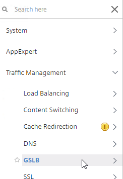
  2. On the right, click View GSLB Configuration.
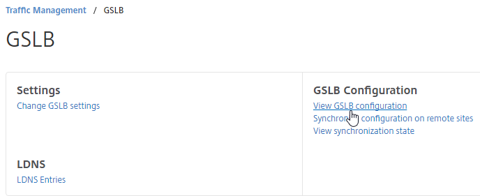
  3. This shows you all of the CLI commands for GSLB. Look for add gslb service commands. You can copy them, and run them (SSH) on other NetScaler pairs that are participating in GSLB.

GSLB Virtual Server

The GSLB Virtual Server is the entity that the DNS name is bound to. GSLB Virtual Server then gives out the IP address of one of the GSLB Services that is bound to it.

For Active/Passive GSLB:

  1. Create a GSLB Virtual Server for the Passive IP address.
    1. Bind the Passive GSLB Service to the Passive GSLB Virtual Server.
  2. Create another GSLB Virtual Server for the Active IP address.
    1. Bind the Active GSLB Service to the Active GSLB Virtual Server.
    2. Configure Backup Virtual Server pointing to the Passive GSLB Virtual Server.
    3. Bind a DNS name to the Active GSLB Virtual Server.
  3. Repeat the GSLB Virtual Server configuration on other NetScaler pairs participating in GSLB.
  4. Delegate the DNS name to NetScaler ADNS.

For Active/Active GSLB:

  1. Create one GSLB Virtual Server.
    1. Bind two or more GSLB Services to the Virtual Server.
    2. Configure the GSLB Virtual Server Load Balancing Method – e.g. Proximity
    3. Configure Site Persistence:
      1. Source IP persistence is configured on the GSLB Virtual Server.
      2. Cookie Persistence is configured on the GSLB Services.
    4. Bind a DNS name to the GSLB Virtual Server.
  2. Repeat the GSLB Virtual Server configuration on other NetScaler pairs participating in GSLB.
  3. Delegate the DNS name to NetScaler ADNS.

Configure the GSLB vServer identically on both appliances:

  1. On the left, expand Traffic Management > GLSB, and click Virtual Servers.
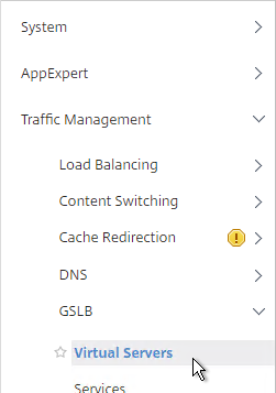
  2. On the right, click Add.
  3. Give the GSLB vServer a descriptive name. For active/active, you can name it the same as your DNS name. For active/passive, you will create two GSLB Virtual Servers, one for each datacenter, so include Active or Passive in the Virtual Server name.
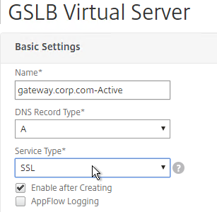
  4. If you intend to bind multiple GSLB Services to this GSLB vServer, then you can optionally check the box for Send all “active” service IPs. By default, GSLB only gives out one IP per DNS query. This checkbox always returns all IPs, but the IPs are ordered based on the GSLB Load Balancing Method and/or GSLB Persistence.
  5. If you configure GSLB to use Static Proximity Load Balancing Method, a new DNS feature called ECS will contain the actual DNS client IP. This dramatically improves the accuracy of determining a user’s location. Without this setting, GSLB can only see the IP address of the user’s configured DNS server instead of the real client IP.

    set gslb vserver <gslb_vserver> -ECS ENABLED -ecsAddrValidation ENABLED
  6. Click OK.
  7. On the left, click where it says No GSLB Virtual Server to GSLBService Binding.
  8. Click the arrow next to Click to select.
  9. Check the box next to an existing GSLB Service and click Select. If your GSLB is active/passive then only bind one service.
  10. If your GSLB is active/active then bind multiple GSLB Services. Also, you’d probably need to configure GSLB persistence (Source IP or cookies).
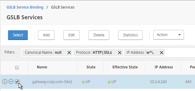
  11. Click Bind.
  12. Click OK.
  13. On the left, click where it says No GSLB Virtual Server Domain Binding.
  14. Enter the FQDN that GSLB will resolve.
  15. If this GSLB is active/passive, there are two options:
    • Use the Backup IP field to specify the IP address that will be handed out if the primary NetScaler is inaccessible or if the VIP on the primary appliance is marked down for any reason.
    • Or, create a second GSLB Virtual Server that has the passive GSLB service bound to it. Don’t bind a Domain to the second GSLB Virtual Server. Then edit the Active GSLB Virtual Server and use the Backup Virtual Server section to select the second GSLB Virtual Server.
  16. Click Bind.
  17. Click OK.
  18. In the ADNS Service section, click OK.
  19. If this is active/active GSLB, you can edit the Method section to enable Static Proximity. This assumes the Geo Location database has already been installed on the appliance.
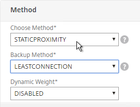
  20. Also for active/active, if you don’t want to use Cookie-based persistence, then you can use the Persistence section to configure Source IP persistence.
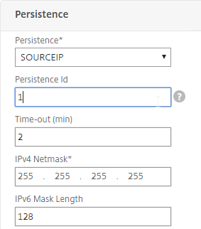
  21. Click Done when done.
  22. If you are configuring active/passive using the backup GSLB Virtual Server method, create a second GSLB Virtual Server that has the passive GSLB service bound to it. Don’t bind a Domain to the second GSLB Virtual Server.
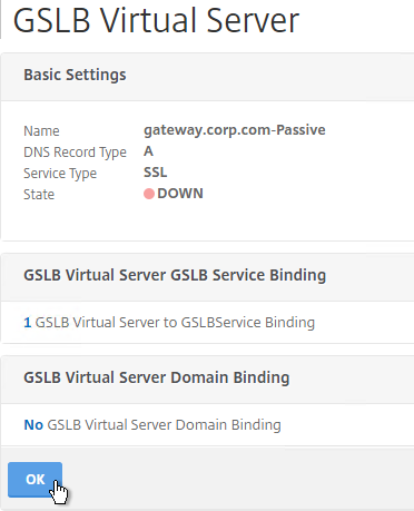
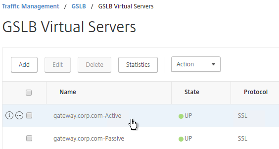
  23. Then edit the Active GSLB Virtual Server and use the Backup Virtual Server section to select the second GSLB Virtual Server.
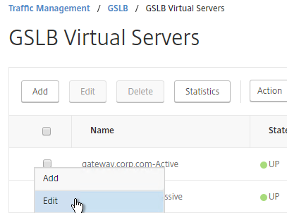
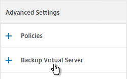
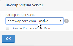
  24. On the left, if you expand Traffic Management > DNS, expand Records, and click Address Records, you’ll see a new DNS record for the GSLB domain you just configured. Notice it is marked as GSLB DOMAIN.
  25. Configure identical GSLB Virtual Servers on the other NetScaler appliance. Both NetScalers must be configured identically. You can also synchronize the GSLB configuration with the remote appliance as detailed in the next section.

GSLB Configuration Synchronization

  1. To manually sync the GSLB configuration from one GSLB Site to another, go to Traffic Management > GSLB.
  2. On the right, in the right column, click Synchronize configuration on remote sites.
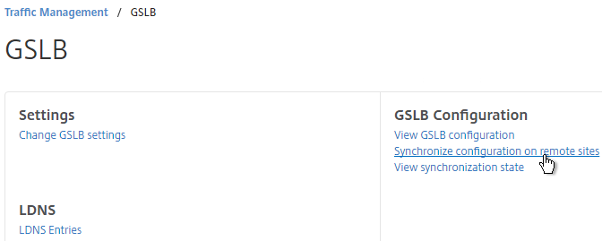
  3. Use the check boxes on the top, if desired. It’s usually a good idea to Preview the changes before applying them. Then click OK to begin synchronization.
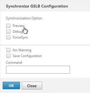
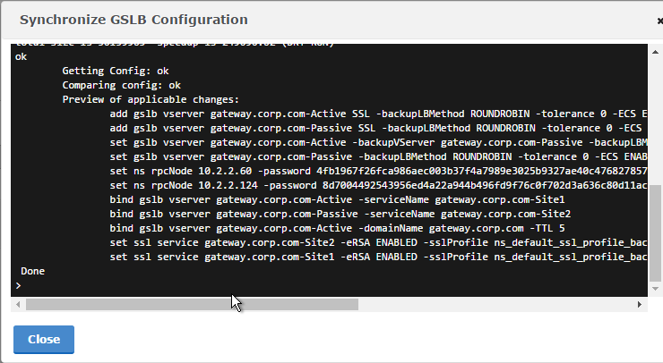
  4. NetScaler 11.1 build 51 and newer has an automatic GSLB Configuration Sync feature, which automatically syncs the GSLB config every 15 seconds. To enable it on the master appliance, go to Traffic Management > GSLB. On the right, in the left column, click Change GSLB settings.
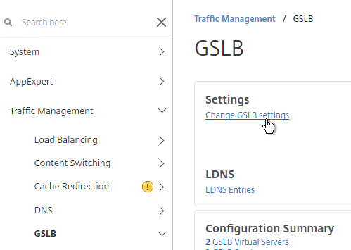
  5. Check the box next to Automatic Config Sync. Only enable this on the one appliance where you are configuring GSLB and want that GSLB config synced to other appliance.
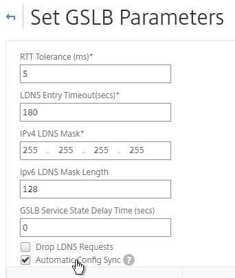
  6. The automatic sync log can be found at /var/netscaler/gslb/periodic_sync.log.
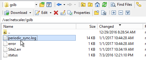
Some notes regarding GSLB Sync:

  • When syncing GSLB Services, it tries to create LB Server objects on the remote appliance. If the GSLB Service IP matches an existing LB Server object, then the GSLB sync will fail. Check the Sync logs for details. You’ll have to delete the conflicting LB Server object before GSLB Sync works correctly.
  • GSLB Sync runs as a script on the BSD shell and thus always uses the NSIP as the source IP.
  • GSLB Sync connects to the remote GSLB Site IP on TCP 3008 (if RPC is Secure) and TCP 22.

Test GSLB

  1. In NetScaler 11.1 build 51 and newer, you can test GSLB DNS name resolution from the GUI by going to Traffic Management > GSLB, and on the right, in the left column, click Test GSLB.
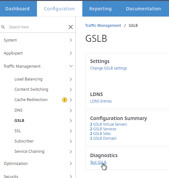
  2. Select a GSLB Domain Name.
  3. Select an ADNS Service IP, and click Test.
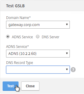
  4. The test performs a dig against the ADNS IP. Verify that the response contains the IP address you expected.
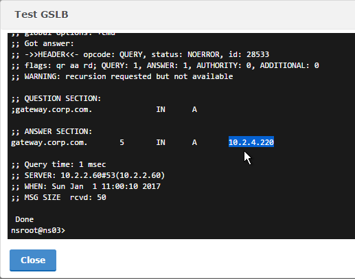
  5. Another method of testing GSLB is to simply point nslookup to the ADNS services, and submit a DNS query for one of the DNS names bound to a GSLB vServer. Run the query multiple times to make sure you’re getting the response you expect.
  6. The NetScaler ADNS services at both GSLB sites should be giving the same response.
  7. To simulate a failure, disable the traffic Virtual Server.
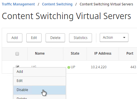
  8. Then the responses should change. Verify on both ADNS services.

  9. Re-enable the traffic Virtual Server, and the responses should return to normal.
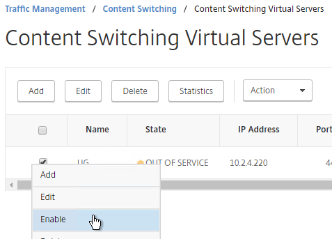

DNS Delegation

If you are enabling GSLB for the domain gateway.corp.com, you’ll need to create a delegation at the server that is hosting the corp.com DNS zone. For public GSLB, you need to edit the public DNS zone for corp.com.

DNS Delegation instructions will vary depending on what product host’s the public DNS zone. This section details Microsoft DNS, but it should be similar in BIND or web-based DNS products.

There are two ways to delegate GSLB-enabled DNS names to NetScaler ADNS:

  • Delegate the individual record. For example, delegate gateway.corp.com to the two NetScaler ADNS services (gslb1.corp.com and gslb2.corp.com).
  • Delegate an entire subzone. For example, delegate the subzone gslb.corp.com to the two NetScaler ADNS services. Then create a CNAME record in the parent DNS zone for gateway.corp.com that is aliased to gateway.gslb.corp.com. When DNS queries make it to NetScaler, they will be for gateway.gslb.corp.com and thus gateway.gslb.corp.com needs to be bound to the GSLB Virtual Server instead of gateway.corp.com. For additional delegations, simply create more CNAME records.

This section covers the first method – delegating an individual DNS record:

  1. Run DNS Manager.
  2. First, create Host Records pointing to the ADNS services running on the NetScalers in each data center. These host records for ADNS are used for all GSLB delegations no matter how many GSLB delegations you need to create.
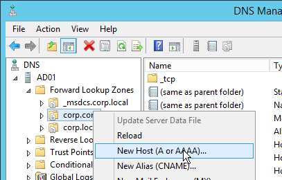
  3. The first Host record is gslb1 (or similar) and should point to the ADNS service (Public IP) on one of the NetScaler appliances.
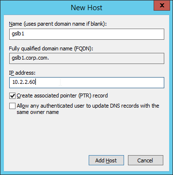
  4. The second Host record is gslb2 and should point to the ADNS Service (public IP) on the other NetScaler appliance.
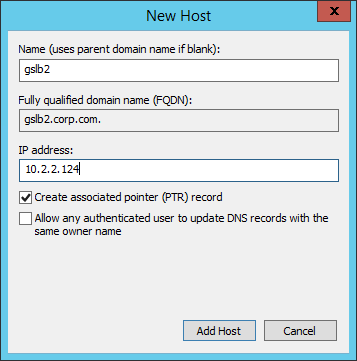
  5. If you currently have a host record for the service that you are delegating to GSLB (gateway.corp.com), delete it.
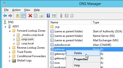
  6. Right-click the parent DNS zone and click New Delegation.
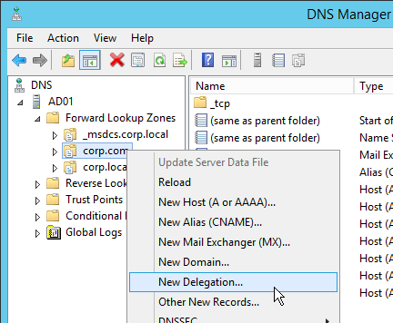
  7. In the Welcome to the New Delegation Wizard page, click Next.
  8. In the Delegated Domain Name page, enter the left part of the DNS record that you are delegating (e.g. gateway). Click Next.
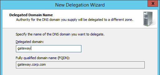
  9. In the Name Servers page, click Add.
  10. This is where you specify gslb1.corp.com and gslb2.corp.com. Enter gslb1.corp.com and click Resolve. Then click OK. If you see a message about the server not being authoritative for the zone, ignore the message.
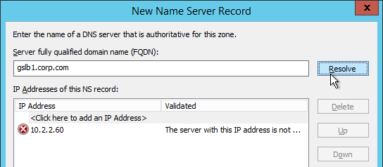
  11. Then click Add to add the other GSLB ADNS server.
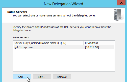
  12. Once both ADNS servers are added to the list, click Next.
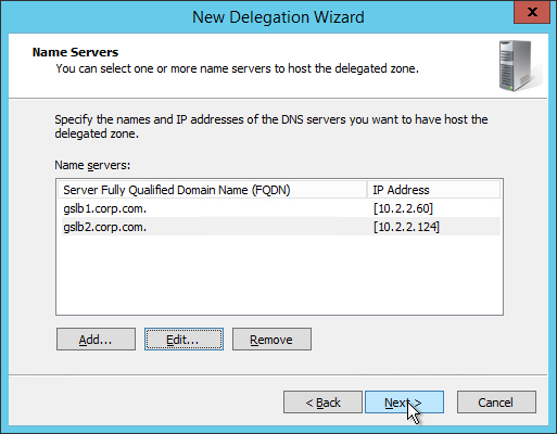
  13. In the Completing the New Delegation Wizard page, click Finish.
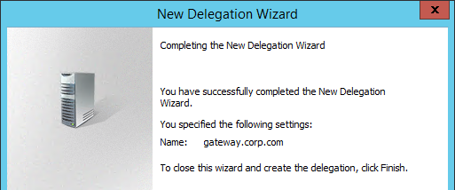
  14. If you run nslookup against your Microsoft DNS server, it will respond with Non-authoritative answer. That’s because it got the response from NetScaler and not from itself.

That’s all there is to it. Your NetScalers are now DNS servers. For active/passive, the NetScalers will hand out the public IP address of the primary data center. When the primary data center is not accessible, GSLB will hand out the GSLB Service IP bound to the Backup GSLB vServer.

Geo Location Database

If you want to use DNS Policies or Static Proximity GSLB Load Balancing or Responders based on user’s location, import a geo location database.

NetScaler has a built-in database at /var/netscaler/inbuilt_db/ that you can use. Or you can download a database. Common free databases are:

For IP2Location, see the blog post Add IP2Location Database as NetScaler’s Location File for instructions on how to import.

To Download GeoLite Legacy:

  1. Download the GeoLite Country database CSV from http://dev.maxmind.com/geoip/legacy/geolite/.
  2. Note: GeoLite City is actually two files that must be merged as detailed at Citrix Blog Post GeoLite City as NetScaler location database. GeoLite Country doesn’t need any preparation.
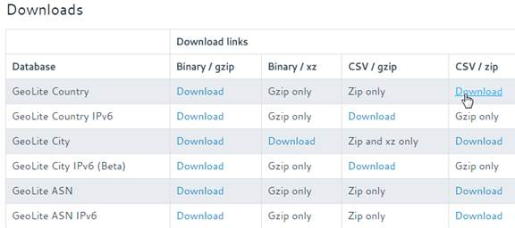
  3. Upload the extracted database (.csv file) to the NetScaler appliance at /var/netscaler/locdb.
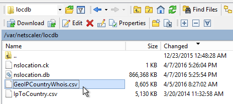
To import the Geo database (including the built-in database):

  1. In the NetScaler GUI, on the left, expand Traffic Management, expand GSLB, expand Location, and click Static Databases.
  2. On the right, click Add.
  3. Change the Import From selection to File.
  4. Click Choose File.
  5. For the built-in database, browse to /var/netscaler/inbuilt_db/ and open Citrix_NetScaler_InBuilt_GeoIP_DB.csv. To browse to the directory, select var and then click Open. Repeat for each directory until you reach /var/netscaler/inbuilt_db.
  6. Or browse to the Geo Location database file you uploaded and open it.
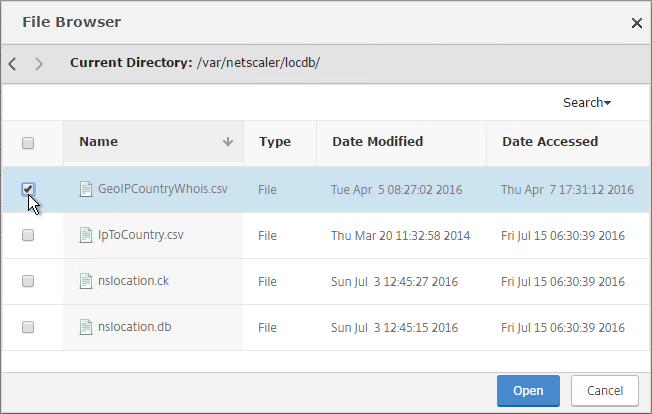
  7. In the Location Format field, if using the built-in database, select netscaler, and click Create.
  8. If using GeoLite Country, select geoip-country and click Create.
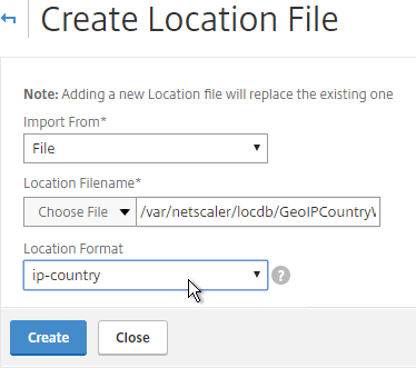
  9. When you open a GSLB Service, the public IP will be translated to a location.

You can use the Geo locations in a DNS Policy, static proximity GSLB Load Balancing, or Responders:
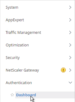
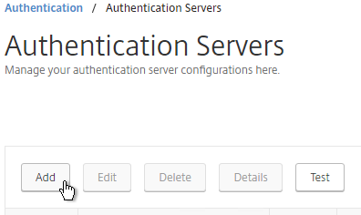
NetScaler Gateway 11.1 – SSL VPN

Last Modified: Nov 7, 2020 @ 6:35 am

Navigation

💡 = Recently Updated

Overview

Here’s an overview of the NetScaler Gateway connection process:

  1. Users use SSL/TLS to connect to a NetScaler Gateway Virtual Server (VIP).
  2. NetScaler Gateway prompts the user for authentication.
  3. Once the user is authenticated, NetScaler Gateway uses Session Policies/Profiles to determine what happens next.

NetScaler Gateway supports five different connection methods:

  • ICA Proxy to XenApp/XenDesktop – the client is built into Citrix Receiver
  • SSL VPN – requires installation of NetScaler Gateway plug-in
  • Clientless – browser only, no VPN client, uses rewrite
  • Secure Browse – from MDX-wrapped mobile applications (XenMobile), uses rewrite
  • RDP Proxy – only RDP client is needed

You can configure NetScaler Gateway Session Policies/Profiles to only use one of the connection methods. Or NetScaler Gateway can be configured to let users choose between ICA Proxy, Clientless, and SSL VPN connection methods. Here’s a sample Client Choices screen using the RfWebUI theme:

Session Policies/Profiles have several settings that control the behavior seen after authentication:

  • ICA Proxy – ON or OFF
    • If ON, then ICA Proxy is the only connection method allowed, overriding the other connection methods.
    • ICA Proxy does not launch the VPN client. It only needs Citrix Receiver.
    • ICA Proxy shows the Webpage that’s configured in the Web Interface Address field of the Session Profile. This is typically the StoreFront Receiver for Web page, but technically it can be any internal website.
    • If OFF, that doesn’t mean ICA Proxy doesn’t work. You can still send ICA traffic to the NetScaler Gateway Virtual Server, and the NetScaler Gateway Virtual Server will still proxy it to internal VDAs.
    • Setting it to OFF allows the other connection methods to function. For example, Clientless Access can show both NetScaler Gateway Bookmarks and StoreFront published apps. If VPN is launched, then the portal page shown to the user after the tunnel is established can contain the StoreFront published applications.
  • Clientless Access – On, Off, Allow
    • If On, then Clientless is the only connection method allowed, assuming ICA Proxy is not set to ON. After the user logs in, the user is presented with a portal page that contains a list of bookmarks and/or StoreFront published icons. The VPN Client is not launched.
    • The Home Page setting in the Session Profile allows you to display an internal website instead of displaying the NetScaler Gateway Portal Page.
    • Bookmarks are configured at NetScaler Gateway > Resources > Bookmarks. You can bind the Bookmarks (Urls) to the NetScaler Gateway Virtual Server, or to AAA Groups.
    • Only Bookmarks configured for Clientless Access will work. The internal websites are rewritten so they are proxied through NetScaler Gateway. For example, if the internal website is http://intranet.corp.local, then Gateway rewrites them to https://gateway.corp.com/cvpn/http/internal.corp.local. This causes the web browser to send the HTTP Request to NetScaler Gateway, which then forwards the HTTP Request to the internal web server. No VPN needed.
  • Plug-in Type – Windows/MAC OS X
    • If both Clientless and ICA Proxy are set to Off, then the VPN Client will be downloaded and launched.
    • Once the VPN tunnel is established, the webpage configured in the Home Page setting is displayed. Or the NetScaler Gateway Portal Page (Clientless Access) is displayed if no Home Page is configured. The Bookmarks in the Portal Page can link to internal websites that are only accessible through a VPN tunnel. Or Bookmarks can be configured for Clientless Access.
    • Additional Gateway objects control VPN behavior including: DNS Suffix, Intranet Applications, Intranet IPs, and Authorization Policies.
  • Client Choices – checked or unchecked
    • If Client Choices is checked, then it displays a page containing up to three buttons corresponding to the connection methods shown above. The Network Access with the NetScaler Gateway Plug-in (VPN)  button is always displayed. The Clientless Access button is displayed if Clientless Access is set to On or Allow. The Virtual App and Desktop Access button is displayed if a Web Interface Address is configured.

Here are some characteristics of Session Policies/Profiles:

  • Policy Expression – If the Session Policy Expression is true, then the settings contained in the Session Profile are applied.
    • The Session Profile is also sometimes called the Action. That’s because all NetScaler policies follow a standard structure – if the expression evaluates to True, then perform the Action. For Session Policies in particular, the policy Action = Session Profile.
    • Session Policy Expressions are typically ns_true, which is always true, or an Endpoint Analysis (EPA) Scan created using the OPSWAT EPA Editor. In the latter case, the Session Profile only applies if the EPA scan succeeded.
  • Policy Bind Points – Session Policies can be bound to three different bind points – NetScaler Gateway Virtual Server, AAA Groups, and AAA User.
    • When bound to a NetScaler Gateway Virtual Server, the Session policy/profile applies to all users that log into that Virtual Server.
    • When bound to a AAA Group, the Session policy/profile only applies to members of the AAA group (Active Directory group or local group)
    • When  bound to a AAA User, the Session policy/profile only applies to the AAA user (Active Directory user or local user)
  • Profile Conflicts – Multiple Session Policies/Profiles could apply to a single session. In this case, the Profile settings are merged. But if there’s a conflict (e.g. one Session Profile enables Clientless access, but another Session Profile disables Clientless access), then which one wins?
    • Priority number – When you bind a Session Policy to a bind point, you specify a priority number. This priority number usually defaults to 100.
    • Lowest priority number wins – The Session Policy bind point that has the lowest priority number, wins. Session Policies bound with a priority of 80 will win over Session Policies bound with a priority of 100. Remember, for settings that don’t conflict, the two Profiles merge, but for settings that do conflict, the lower priority number policy/profile settings win.
    • Bind point types – The type of bind point doesn’t matter. If you bind a Session Policy to a AAA Group with a priority of 100, and you also bind a Session Policy to the NetScaler Gateway Virtual Server with a priority of 80, then the conflicting settings in the Session Policy bound to the NetScaler Gateway Virtual Server will win. You might think that AAA-bound policies always override Virtual Server-bound policies, but that is not the case.

AAA Groups are a critical component of NetScaler Gateway VPN configuration:

  • Group extraction – Make sure the LDAP Policy/Server is configured to extract to the user’s Active Directory Groups.
  • Create AAA Groups on the NetScaler that match exactly (case sensitive) with the user’s Active Directory Group Name.
  • You can then bind policies and other Gateway objects to the AAA Group, and these bindings only affect that particular AAA Group. These bindings include:
  • If the user belongs to multiple AAA Groups, then policies are applied as follows:
    • Session Policies – the settings are merged, unless there’s a conflict. If a conflict, then the policy with the lowest priority number wins.
    • Bookmarks, Intranet Applications, and Authorization Policies are merged.
    • Intranet IPs (IP Pool) are probably random allocation. It’s probably best to make sure a user only belongs to one AAA Group that assigns Intranet IPs.
  • You can also create local AAA Groups that are unrelated to Active Directory groups. There are several ways of getting users into these local AAA groups:
    • Create local AAA Users and assign them to the AAA Group
    • Configure Session Policy/Profile with a Client Security Check String (EPA Scan). If the scan succeeds, users are placed into local Authorization AAA Groups. If the scan fails, then users are placed into a local Quarantine AAA Group and removed from all other AAA Groups.
    • When users are authenticated with a particular authentication server, the authentication server can be configured to place users into a Default Authentication Group. This lets you apply different Session Policy/Profiles (and other Gateway objects) depending on how the user authenticated.

NetScaler Gateway supports Client Security Expressions (Endpoint Analysis expressions) at three different locations:

  • Preauthentication Policy Expression
    • If the EPA Scan succeeds, then the user is allowed to login.
    • If the EPA Scan fails, then the user is not allowed to login.
    • Preauthentication Policies are bound to NetScaler Gateway Virtual Servers only, and thus applies to all users of that Virtual Server.
  • Session Policy Expression
    • This type of EPA Scan is configured in the Session Policy Expression, not the Profile.
    • If the EPA Scan succeeds, then the settings in the Session Profile are applied to the session.
    • If the EPA Scan fails, then the Session Profile is ignored. Other Session Policies expressions are still evaluated. Remember, Session Policy/Profiles merge, so all applicable Session Policies must be considered.
    • A limitation of this EPA method is that nothing negative happens. Instead, you typically design higher priority number (lower priority) Session Policies with restrictive settings so that if the EPA Scans fail, then users still get something. For example, youcan  configure your highest priority number Session Policy/Profile with StoreFront (ICA Proxy) only. In the lower priority number Session Policies/Profiles, VPN might be enabled, but only if the EPA scan succeeds. More restrictive Session Profiles usually uncheck Client Choices, and enable Clientless Access or ICA Proxy.
    • This method of EPA Scans is used in SmartAccess and SmartControl configurations.
  • Session Profile > Security > Advanced Settings > Client Security Check String
    • If the EPA Scan succeeds, add the user to the listed Authorization AAA Groups.
    • If the EPA Scan fails, add the user to the selected Quarantine Group, and remove the user from all other AAA Groups.
  • Assigning EPA scans to Session Policies and Session Profiles is also known as Post-Authentication EPA Scans.
  • If Endpoint Analysis is configured anywhere, then an Endpoint Analysis plug-in is downloaded to the Windows or Mac client.

Prerequisites

Except for ICA Proxy, all NetScaler Gateway connection methods require a NetScaler Gateway Universal License for each concurrent session. Go to System > Licenses and make sure NetScaler Gateway User licenses are installed.

Also make sure the maximum AAA users equals the number of licenses. Go to NetScaler Gateway > Global Settings > Change authentication AAA settings.

DNS usually needs to function across the VPN tunnel. Go to Traffic Management > DNS > Name Servers to add DNS servers.

Create Session Profile

To enable SSL VPN: first create the Session Profile. Then create a Session Policy.

You can create multiple session Policies/Profiles with different settings. Then you can bind these Session Policies to AAA groups and/or NetScaler Gateway Virtual Servers.

To enable SSL VPN in a Session Profile:

  1. On the left, expand NetScaler Gateway, expand Policies, and click Session.
  2. On the right, switch to the Session Profiles tab, and click Add.
  3. Name the profile VPN or similar.
  4. In Session Profiles, every line has an Override Global checkbox to the right of it. If you check this box next to a particular field, then the field in this session profile will override settings configured globally or in a lower priority session policy.
  5. Switch to the Network Configuration tab.
  6. You will find a setting that lets you select a DNS Virtual Server. Or if you don’t select anything, then the tunnel will use the DNS servers configured under Traffic Management > DNS > Name Servers.
  7. Switch to the Client Experience tab. This tab contains most of the NetScaler Gateway VPN settings.
  8. Override Plug-in Type and set it to Windows/Mac OS X.
  9. On the Client Experience tab, override Split Tunnel and make your choice. Setting it to OFF will force all traffic to use the tunnel. Setting it to ON will require you to create Intranet Applications so the NetScaler Gateway Plug-in will know which traffic goes through the tunnel, and which traffic goes directly out the client NIC (e.g. to the Internet). REVERSE means all traffic goes through the tunnel except for the addresses defined in Intranet Applications.
  10. On the Client Experience tab, there are timers that can be configured. Global Settings contains default timers, so you might want to configure this Session Profile to override the defaults and increase the timeouts. See Configuring Time-Out Settings at Citrix Docs for details.
    1. Client Idle Time-out is a NetScaler Gateway Plug-in timer that disconnects the session if there is no user activity (mouse, keyboard) on the client machine.
    2. Session Time-out is a NetScaler timer that disconnects the session if there is no network activity for this duration.
    3. In addition to these two timers, on the Network Configuration tab, under Advanced Settings, there’s a Forced Timeout setting.

  11. By default, once the VPN tunnel is established, a portal page appears containing bookmarks, and StoreFront published icons. An example of the portal page in the RfWebUI theme is shown below:
  12. The X1 theme is shown below:
  13. On the Client Experience tab, the Home Page field lets you override the the default portal page, and instead display a different webpage (e.g. Intranet). This homepage is displayed after the VPN tunnel is established (or immediately if connecting using Clientless Access).
  14. NetScaler Gateway 11.1 can now automatically start the VPN tunnel whenever the user is remote. Click the plus icon next to AlwaysON Profile Name.
  15. Give the profile name. Hover over the question marks to see what each of them does. Then click Create. More info at AlwaysON at Citrix Docs.
  16. Additional VPN settings can be found by clicking Advanced Settings near the bottom of the Client Experience tab.
  17. Under Client Experience > Advanced Settings, on the General tab, there are settings to run a login script at login, enable/disable Split DNS, and enable Local LAN Access. Use the question marks to see what they do. Reliable DNS occurs when Split DNS is set to Remote.
  18. Note: if Split Tunnel is OFF, and if Split DNS is set to REMOTE, NetScaler only returns one IP address to DNS queries. This behavior can be changed by following Citrix CTX200243 DNS Query Responds with Only One IP to Client PC When Connected Through NetScaler Gateway Full VPN.  💡
  19. Under Client Experience > Advanced Settings, on the General tab, is a checkbox for Client Choices. This lets the user decide if they want VPN, Clientless, or ICA Proxy (StoreFront). Without Client Choices, one of the connection methods will occur automatically, depending on what’s enabled.
  20. On the main Client Experience tab, if you enabled Client Choices, you can set Clientless Access to Allow to add Clientless to the list of available connection methods.
  21. An example of Client Choices is shown below:
  22. The Client Experience > Advanced Settings section has additional tabs. A commonly configured tab is Proxy, which allows you to enable a proxy server for VPN users.
  23. Back in the main Session Profile, switch to the Security tab.
  24. Set the default authorization to Allow or Deny. If Deny (recommended), you will need to create authorization policies to allow traffic across the tunnel. You can later create different authorization policies for different groups of users.
  25. On the Published Applications tab, set ICA Proxy to Off. This ensures VPN is used instead of ICA Proxy.
  26. Configure the Web Interface Address, to embed StoreFront into the default portal page. Note: for X1 theme, additional iFrame configuration is required on the StoreFront side as detailed below. RfWebUI theme does not need any StoreFront changes.
  27. From Michael Krasnove: if you configured the Session Policy to direct users to StoreFront, but aren’t using RfWebUI, then placing the following code in c:\inetpub\wwwroot\Citrix\StoreWeb\custom\script.js will cause StoreFront to end the VPN tunnel when the user logs off of StoreFront.
    var LOGOFF_REDIRECT_URL = 'https://YourGatewayFQDN.com/cgi/logout';
     
    // Prevent the default "logoff" screen from being displayed
    CTXS.Controllers.LogoffController.prototype._handleLogoffResult = $.noop;
     
    CTXS.Extensions.afterWebLogoffComplete = function () {
     window.location.href = LOGOFF_REDIRECT_URL;
    };
  28. Click Create when you’re done creating the Session Profile.

Create Session Policy

Once the Session Profile is created, you need a Session Policy linked to it. The Session Policy contains an expression, where if true, then the Session Profile is applied.

If multiple Session Policies apply to a particular connection, then the settings in the policies are merged. For conflicting settings, the Session Policy with the highest priority (lowest priority number) wins. Session Policies bound to AAA groups only override Session Policies bound to NetScaler Gateway Virtual Servers if the AAA group bind point has a lower priority number. In other words, priority numbers are evaluated globally no matter where the Session Policy is bound. You can run the command nsconmsg –d current –g pol_hits to see which Session Policies are applying to a particular connection. See CTX214588 Understanding Session Policy Priority on Different Bind Points.

You can also bind Endpoint Analysis expressions to a Session Policy so that the Session Policy only applies to machines that pass the Endpoint Analysis scan.

To create a Session Policy that is linked to a Session Profile:

  1. In the right pane, switch to the Session Policies, tab and click Add.
  2. Give the policy a descriptive name.
  3. Change the Profile drop-down to the VPN Profile you just created.
  4. Add a policy expression. You can enter ns_true, which applies to all connections. This box uses classic expression syntax.
  5. Or you can add Endpoint Analysis scans. If the Endpoint Analysis scan succeeds, then the session policy is applied. If the Endpoint Analysis scan fails, then this session policy is skipped, and the next one is evaluated. This is how you can allow VPN if EPA scan succeeds, but all failed EPA scans will get a different session policy that only has ICA Proxy enabled.
  6. To add an Endpoint Analysis scan, use one of the Editor links on the right.
  7. Configure OPSWAT scans in the OPSWAT EPA Editor.
  8. Configure Client Security Expressions in the Expression Editor.
  9. You can combine multiple Endpoint Analysis scan expressions using Booleans (&&, ||, !). Click Create when done.

Bind Session Policy

Most of the NetScaler Gateway configuration objects can be bound to NetScaler Gateway Virtual Server, AAA Group, or both. This section details binding of Session Policies, but the other NetScaler Gateway objects (e.g. Authorization Policies) can be bound using similar instructions.

If you bind the Session Policy to a AAA group, only members of that Active Directory group will evaluate the policy expression and potentially receive the Session Profile settings.

Bind the new Session Policy to a NetScaler Gateway Virtual Server, or a AAA group.

  1. To bind to a NetScaler Gateway Virtual Server, edit a NetScaler Gateway Virtual Server (or create a new one).
  2. Click the pencil icon for the Basic Settings section.
  3. Click More.
  4. Make sure ICA Only is unchecked and click OK. If this box is checked then VPN, Clientless, and other features won’t work.
  5. Note: with this box unchecked, Gateway Universal licenses are now required for all users connecting through this Gateway vServer.
  6. Scroll down to the Policies section, and click the Plus icon.
  7. In the Choose Type page, select Session, Request and click Continue.
  8. Click to select.
  9. Select the policy, and click Select.
  10. Click Bind.
  11. If you bind multiple session policies, the policies are merged based on priority number. This is where you specify a priority for each bound policy. See CTX214588 Understanding Session Policy Priority on Different Bind Points.
  12. You can also edit the policy or profile from this screen by clicking the ellipsis icon next to each bound policy.
  13. While editing the Gateway vServer, consider changing the Portal Theme to RfWebUI. This changes the default portal page to look identical to StoreFront. RfWebUI requires StoreFront to be 3.6 or newer.
  14. To bind to a AAA Group, go to NetScaler Gateway > User Administration > AAA Groups.
  15. Add a group with the same name (case sensitive) as the Active Directory group name. This assumes your LDAP policies/server are configured for group extraction (Group Attribute, and Sub Attribute).
  16. Edit the AAA Group.
  17. On the right, in the Advanced Settings column, add the Policies section.
  18. Click the plus icon to bind one or more Session Policies.
  19. If you want these Session Policies to override the Session Policies bound to the NetScaler Gateway Virtual Server, then make sure the Session Policies bound to the AAA Group have lower priority numbers. See CTX214588 Understanding Session Policy Priority on Different Bind Points.


NetScaler Gateway Plug-in Installation

Here is what the user sees when launching the VPN session for the first time. This assumes the user is an administrator of the local machine.


And then the default portal page is displayed. If using the RfWebUI theme, it might prompt you to install Receiver.

Only administrators can install the NetScaler Gateway Plug-in. You can download the Gateway plug-in from the NetScaler appliance at /var/netscaler/gui/vpns/scripts/vista and push it to corporate-managed machines. Or you can download VPN clients from Citrix.com. The VPN client version must match the NetScaler firmware version.

While a VPN tunnel is established, you can open the Gateway Plug-in to see status. If the Gateway Plug-in is merged with Receiver, right-click Receiver, click Advanced Preferences, click NetScaler Gateway Settings and click Open.

Or, right-click the Gateway Plug-in icon, and click Open.

The hamburger menu on the left lets you see more info about the VPN tunnel.

If the Gateway VPN session isn’t established, you can open the Gateway plug-in, and login. No browser needed.

The Configuration page lets you enable Logging. Then the Logging page lets you collect the logs. See Citrix CTX138155 How to Collect Client VPN Logs for NetScaler Gateway.  💡

VPN Client (NetScaler Gateway Plug-in) Session Profile Settings

  1. By default, if Receiver and NetScaler Gateway Plug-in are installed on the same machine, then the icons are merged. To see the NetScaler Gateway Plug-in Settings, you right-click Receiver, open Advanced Preferences, and then click NetScaler Gateway Settings. This makes it difficult to log off.

  2. You can configure the Session Policy/Profile to prevent the NetScaler Gateway Plug-in from merging with Receiver. Edit your VPN Session Policy/Profile. On the Client Experience tab, scroll down, and check the box next to Advanced Settings.
  3. Check the box next to Show VPN Plugin-in icon with Receiver. This causes the two icons to be displayed separately thus making it easier to access the NetScaler Gateway Plug-in settings, including Logoff.


  4. When the user logs off of VPN, a Cleanup page is displayed. This can be enabled or disabled in a Session Profile on the Client Experience tab.

  5. The cleanup options can be forced in a Session Profile on the Client Experience tab, under Advanced Settings > Client Cleanup.
  6. Whenever NetScaler firmware is upgraded, all users will be prompted to upgrade their VPN clients. You can edit a Session Policy/Profile, and use the Upgrade drop-downs to disable the automatic upgrade.
  7. The Plugin Upgrade settings are also configurable in the Gateway vServer, in the Basic Settings section.

Authorization Policies

If your Session Profile has Security tab > Default Authorization set to Deny (recommended), then create Authorization Policies to allow access across the tunnel.

  1. On the left, under NetScaler Gateway, expand Policies, and click Authorization.
  2. On the right, click Add.
  3. Name the Authorization Policy.
  4. Select Allow or Deny.
  5. NetScaler Gateway requires you to Switch to Classic Syntax. The other syntax option is for AAA.
  6. Enter an expression. Use the Expression Editor link to build an expression. You can specify destination IP subnets, destination port numbers, etc.
  7. Click Create when done.
  8. Authorization Policies are usually bound to AAA groups. This allows different groups to have different access across the tunnel.
  9. On the right, in the Advanced Settings column, add the Authorization Policies section.
  10. Then click where it says No Authorization Policy to bind policies.

Intranet Applications

If you enabled Split Tunnel, then you’ll need to create Intranet Applications to specify which traffic goes through the tunnel.

  1. On the left, under NetScaler Gateway, expand Resources, and click Intranet Applications.
  2. On the right, click Add.
  3. Enter a name for the Internal subnet.
  4. Change the Interception Mode to TRANSPARENT.
  5. Enter an IP subnet. Only packets destined for this network go across the tunnel.
  6. Then click Create.
  7. Create additional Intranet applications for each internal subnet.
  8. Intranet Applications are usually bound to the Gateway Virtual Server, but you can also bind them to AAA Groups.
  9. On the right, in the Advanced Settings column, add the Intranet Applications section.
  10. On the left, click No Intranet Application to bind Intranet Applications.

DNS Suffix

Specify a DNS Suffix for Split DNS to function with single label DNS names.

  1. On the left, under NetScaler Gateway, expand Resources, and click DNS Suffix.
  2. On the right, click Add.
  3. Enter the DNS Suffix, and click Create. You can add multiple suffixes.

Bookmarks

Bookmarks are the links that are displayed in the default portal interface. They can point to websites, or RDP addresses.

  1. Under NetScaler Gateway, expand Resources, and click Bookmarks.
  2. On the right, click Add.
  3. Give the bookmark a name and display text.
  4. Enter a website or RDP address.
  5. The other fields are for Single Sign-on through Unified Gateway. Click Create.
  6. Bookmarks (aka Published Applications > Url) are usually bound to AAA groups so different groups can have different bookmarks. But it’s also possible to bind Bookmarks to NetScaler Gateway Virtual Servers.
  7. If NetScaler Gateway Virtual Server, add the Published Applications section to bind Bookmarks (Url).
  8. For AAA Group, it’s the Bookmarks section.
  9. On the left, find the Published Applications section and click No Url to bind Bookmarks.

VPN Client IP Pools (Intranet IPs)

By default, NetScaler Gateway VPN clients use NetScaler SNIP as their source IP when communicating with internal resources. To support IP Phones or endpoint management, you must instead assign IP addresses to VPN clients.

Any IP pool you add to NetScaler must be reachable from the internal network. Configure a static route on the upstream router. The reply traffic should be routed through a NetScaler SNIP. Or the NetScaler can participate in OSPF.

When a client is assigned a client IP, this IP address persists across multiple sessions until the appliance reboots, or until the appliance runs out of IPs in the pool.

  1. Edit a NetScaler Gateway Virtual Server or a AAA group.
  2. On the right, in the Advanced Settings section, click the plus icon next to Intranet IP Addresses.
  3. On the left, click where it says No Intranet IP.
  4. Enter a subnet and netmask. Click Bind.
  5. In a Session Policy/Profile, on the Network Configuration tab, check the box next to Advanced Settings.
  6. Use the Intranet IP drop-down to configure the behavior when there are more VPN clients than available IPs in the address pool.
  7. If you set it to NOSPILLOVER, then users can only have one VPN session, as described in CTX218066 How to Limit One Session Per User on NetScaler Gateway?.  💡


  8. To see the Client IP address, on the client side, after the tunnel is established, right-click the NetScaler Gateway Plug-in, and click Open.
  9. See the Internal network address.
  10. To see the client IP on the NetScaler, go to NetScaler Gateway, and on the right is Active user sessions.
  11. Select one of the views, and click Continue.
  12. The right column contains the Intranet IP.

StoreFront in Gateway X1 Portal

If you enabled the RfWebUI theme, then no StoreFront configuration is necessary.

But if you want to embed StoreFront in the other Gateway themes (X1, Default, Green Bubble), then follow these instructions.

  1. On StoreFront, edit the file C:\Inetpub\wwwroot\Citrix\StoreWeb\web.config.
  2. On the bottom, there are three sections containing X-Frame-Options. Change all three of them from deny to allow.
  3. Also change frame-ancestors from none to self.
  4. In NetScaler, go to NetScaler Gateway > Global Settings and click Configure Domains for Clientless Access.
  5. Change the selection to Allow Domains, enter your StoreFront FQDN and click the plus icon.
  6. Click OK.
  7. In a Session Policy/Profile, on the Client Experience tab, make sure Single Sign-on to Web Applications is enabled.
  8. On the Published Applications tab, configure the Web Interface Address to point to the StoreFront Receiver for Web page.
  9. Configure the Single Sign-on domain to match what’s configured in StoreFront.
  10. The Applications page of the 3-page portal (e.g. X1 theme) should automatically show the StoreFront published icons.

Quarantine Group

NetScaler Gateway can be configured so that if Endpoint Analysis scans fail, then the user is placed into a Quarantine Group. You can bind session policies, authorization policies, etc. to this quarantine group. Policies bound to other AAA groups are ignored.

  1. Go to NetScaler Gateway > User Administration > AAA Groups.
  2. Add a new local group for your Quarantined Users. This group is local, and does not need to exist in Active Directory.
  3. Create a new Session Profile.
  4. On the Security tab, check the box next to Advanced Settings.
  5. Check the box to the right of Client Security Check String.
  6. Use the Editor links to add an Endpoint Analysis expression.
  7. Just below the Client Security Check String, select the previously created Quarantine Group.
  8. Click Create when done.
  9. Create a Session Policy and select the Session Profile you just created.
  10. Enter ns_true as the expression. Then click Create.
  11. Edit your Gateway Virtual Server and bind the new session policy.
  12. Bind session policies, authorization policies, etc. to your quarantine AAA group. These policies typically limit access to the internal network so users can remediate. Or, it might simply display a webpage telling users how to become compliant.
  13. To troubleshoot Quarantine policies, use the command nsconmsg –d current –g pol_hits.
  14. Another option is to use the session policy bound to the Quarantine Group for SmartAccess configuration.
  15. Gateway Insight shows users that failed EPA scans and their quarantine status.

Related Pages

NetScaler Management and Analytics System (MAS) 11.1

Last Modified: Nov 6, 2020 @ 6:51 am

Navigation

The newer 12.0 version of NetScaler MAS is detailed in a different post.

💡 = Recently Updated

Planning

NetScaler MAS is a replacement for NetScaler Insight Center, Command Center, and Control Center. It’s a combination of these three different tools.

NetScaler MAS is a licensed product. It’s free for 30 vServers. Beyond that, licenses can be purchased in 100 vServer packs. Alternatively, you can continue to use Insight Center and/or Command Center.

Requirements for HDX Insight (AppFlow):

  • Your NetScaler appliance must be running Enterprise Edition or Platinum Edition.
  • NetScaler must be 10.1 or newer.
  • HDX Insight works with the following Receivers:
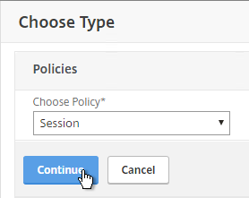
    • Receiver for Windows must be 3.4 or newer.
    • Receiver for Mac must be 11.8 or newer.
    • Receiver for Linux must be 13 or newer.
    • Notice no mobile Receivers. See the Citrix Receiver Feature Matrix for the latest details.
  • For Session Reliability, NetScaler 10.5 build 54 and newer.
  • ICA traffic must flow through a NetScaler appliance:


For ICA round trip time calculations, in a Citrix Policy, enable the following settings:
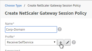
  • ICA > End User Monitoring > ICA Round Trip Calculation
  • ICA > End User Monitoring > ICA Round Trip Calculation Interval
  • ICA > End User Monitoring > ICA Round Trip Calculation for Idle Connections

Citrix CTX204274 How ICA RTT is calculated on NetScaler Insight: ICA RTT constitutes the actual application delay. ICA_RTT = 1 + 2 + 3 + 4 +5 +6:
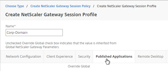
  1. Client OS introduced delay
  2. Client to NS introduced network delay (Wan Latency)
  3. NS introduced delay in processing client to NS traffic (Client Side Device Latency)
  4. NS introduced delay in processing NS to Server (XA/XD) traffic (Server Side Device Latency)
  5. NS to Server network delay (DC Latency)
  6. Server (XA/XD) OS introduced delay (Host Delay)


The version/build of NetScaler MAS must be the same or newer than the version/build of the NetScaler appliances.

Import Appliance

You can use either the vSphere Client, or the vSphere Web Client, to import the appliance. In vSphere Client, open the File menu, and click Deploy OVF Template. vSphere Web Client instructions are shown below.

You might see this operating system error when not using the vSphere Web Client. Click Yes to proceed. It seems to work.

  1. Download NetScaler MAS for ESX, and then extract the .zip file.
  2. In vSphere Web Client, right-click a cluster, and click Deploy OVF Template.
  3. In the Select source page, select Local file, and browse to the NetScaler MAS .ovf files. Click Next.
  4. In the Review details page, click Next.
  5. In the Select name and folder page, enter a name for the virtual machine, and select an inventory folder. Then click Next.
  6. In the Select a resource page, select a cluster or resource pool, and click Next.
  7. In the Select storage page, select a datastore. If a single appliance, or if a database appliance, due to high IOPS, SSD or Flash is recommended.
  8. Change the virtual disk format to Thin Provision. Click Next.
  9. In the Setup networks page, choose a valid port group, and click Finish.
  10. In the Ready to Complete page, check the box next to Power on after deployment, and click Finish.
  11. If you try to power on the VM, and you see a message about freeBSD not being supported, then you might have to upgrade the VM Hardware Compatibility Level. VM hardware version 4 seems to be too old.  💡


  12. CTX219344 How to Increase Storage space for NetScaler MAS: power off appliance, add a second disk that’s larger than the first, then power on the appliance.  💡

IP Configuration and High Availability

  1. Open the console of the virtual machine, and configure an IP address.
  2. Enter 7 when done.
  3. When prompted for Deployment Type, enter 1 for NetScaler MAS Server. The first appliance must always be NetScaler MAS Server. Notice the new option for Remote Backup Node.  💡
  4. If you want to deploy two NMAS appliances and HA pair them, enter no for Standalone and yes for First Server Node.
  5. Note: HA is only for database redundancy. All other traffic (SNMP, AppFlow) only goes to one node.
  6. Enter Yes to reboot.
  7. Deploy another appliance.
  8. This time, when asked if First Server Node, enter no. You will then be asked for the IP address of the first node. Enter the nsroot password.
  9. From CTX220000 How to reboot or shutdown Netscaler MAS using CLI: when using the MAS CLI, do not use the reboot command since it will cause data corruption. Instead, run shutdown -r now.
  10. If you need to add a static route to NetScaler MAS, then see CTX223282 How to Add a Static Route on NetScaler MAS.  💡
  11. Once you’ve built all of the nodes, point your browser to the primary NetScaler MAS IP address and login as nsroot/nsroot.
  12. If you see CUXIP, either Skip or Enable the Customer User Experience Improvement Program.
  13. Click Get Started
  14. Select Two servers deployed in High Availability Mode, and click Next.
  15. It should show both nodes. Click Deploy on the top right.
  16. Click Yes to reboot the appliances.
  17. If you login to one of the appliances, at System > Deployment, you’ll see the performance of each node. Notice the Break HA icon on the top right.

  18. You can manage the pair by logging in to either node.
  19. Or you can load balance the pair. Load Balancing is only useful for administration. All other communications (e.g.  SNMP, AppFlow) go directly to one of the nodes. See High Availability Deployment at Citrix Docs for load balancing instructions.

Add Instances

NetScaler MAS must discover NetScaler instances before they can be managed. Citrix Docs How NetScaler MAS Communicates with Managed Instances.

  1. Login to one of the NetScaler MAS appliances.
  2. If you see the Get Started page, click Get Started.
  3. In the Select Deployment Type page, click Next.
  4. On the Add New Instances page, click + New near the top right.

  5. Enter the NSIP address of a NetScaler appliance.
  6. Click the pencil next to ns_nsroot_profile.
  7. Enter the password for the nsroot account.
  8. Enter an SNMP community string that NetScaler MAS will configure on the appliance.
  9. The NetScaler Profile defaults to using https for instance communication. Click OK.
  10. Then click OK to add the instance.
  11. A progress window will appear.
  12. You can add more instances, or just click Finish.
  13. To add more instances later, go to Infrastructure > Dashboard, and on the top right, click All Instances.
  14. Then click New.

Licenses

Virtual Server License Packs

Without licenses, NetScaler MAS only shows 30 Virtual Servers. You can install additional licenses in 100 Virtual Server packs.

  1. Go to Infrastructure > Licenses > Settings.
  2. On the right, notice the Host ID. Allocate your NetScaler MAS licenses to this Host ID. Then use the Browse button to upload the allocated license file.
  3. You can use the Notification Settings section to email you when licenses are almost fully consumed or about to expire.


Allocate licenses to Virtual Servers 

If you have fewer Virtual Servers than the number of installed licenses, then licenses are automatically assigned to all Virtual Servers. You can manually unassign a license and reassign it to a different Virtual Server.

  1. Go to Infrastructure > Licenses > System Licenses.
  2. On the top right, click Modify licensed Virtual Servers.
  3. In the top row, select the type of Virtual Server you want to unlicense or license.
  4. Select one or more Virtual Servers, and click the Mark Unlicensed button.
  5. Click Yes when asked to mark unlicensed.
  6. To allocate a license to a Virtual Server, click the Add Virtual Servers button.
  7. Select the Virtual Server(s) you want to allocate and click Select.
  8. Click Finish now when done.

Enable AppFlow / Insight

  1. Go to Infrastructure > Instances > Instance type (e.g. NetScaler VPX).
  2. Click the ellipsis next to an instance, and then click Enable/Disable Insight.
  3. At the top of the page are boxes you can check.
  4. With Load Balancing selected in the View list, click the ellipsis next to your StoreFront load balancer, and click Enable AppFlow.
  5. Type in true.
  6. Select Web Insight. If App Firewall is enabled on the vServer then also select Security Insight.
  7. HTML Injection injects JavaScript in HTTP responses to measure page load times.
  8. Click OK.
  9. Use the View drop-down to select VPN.
  10. Click the ellipsis next a NetScaler Gateway Virtual Server, and click Enable AppFlow.
  11. In the Select Expression drop-down, select true.
  12. For Export Option, select ICA and HTTP, and click OK. The HTTP option is for Gateway Insight.
  13. The TCP option is for the second appliance in double-hop ICA. If you need double-hop then you’ll also need to run set appflow param -connectionChaining ENABLED on both appliances. See Enabling Data Collection for NetScaler Gateway Appliances Deployed in Double-Hop Mode at docs.citrix.com for more information.
  14. By default, with AppFlow enabled, if a NetScaler High Availability pair fails over, all Citrix connections will drop, and users must reconnect manually. NetScaler 11.1 build 49 adds a new feature to replicate Session Reliability state between both HA nodes.
    1. From Session Reliability on NetScaler High Availability Pair at Citrix Docs: Enabling this feature will result in increased bandwidth consumption, which is due to ICA compression being turned off by the feature, and the extra traffic between the primary and secondary nodes to keep them in sync.
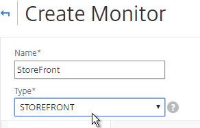
    2. If you still want this feature, on NetScaler 11.1 build 49 and newer, go to System > Settings.
    3. On the right, click Change ICA Parameters.
    4. Check the box next to Session Reliability on HA Failover, and click OK.
  15. AppFlow (e.g. HDX Insight) information can be viewed in NetScaler MAS on the Analytics tab.

Citrix Blog Post – NetScaler Insight Center – Tips, Troubleshooting and Upgrade

Nsroot Password

  1. On the System tab, expand User Administration, and click Users.
  2. On the right, click the ellipsis next to the nsroot account, and click Edit.
  3. Enter a new password.
  4. You can also specify a session timeout. Click OK.

Management Certificate

The certificate to upload must already be in PEM format. If you have a .pfx, you must first convert it to PEM (separate certificate and key files). You can use NetScaler to convert the .pfx, and then download the converted certificate from the appliance.

  1. On the System tab, go to System Administration.
  2. On the right, click Install SSL Certificate.
  3. Click Choose File to browse to the PEM format certificate and key files. If the keyfile is encrypted, enter the password. Click OK.
  4. Click Yes to reboot the system.

System Configuration

  1. Click the System tab on the top of the page.
  2. On the left, click the System Administration node.
  3. On the right, modify settings (e.g.Time Zone) as desired.

  4. To change the Session Timeout, click Change System Settings.

  5. On the right column are additional settings. For example, System Prune Settings, which defaults to deleting SNMP traps after 15 days.

  6. Instances Backup Settings lets you configure the number of backup files to retain for each instance.
  7. There are more settings under System > Analytics Settings.
  8. ICA Session Timeout can be configured by clicking the link. Two minutes of non-existent traffic must occur before the session is considered idle. Then this idle timer starts.
  9. If you are using Web Insight, Configure Data Record Settings lets you enable Reports on the dashboard.

  10. Auditing > Syslog Purge Settings controls how long Syslog data is retained (15 days by default).

  11. On the left, click NTP Servers.
  12. On the right, click Add.


  13. After adding NTP servers, click NTP Synchronization.
  14. Check the box next to Enable NTP Synchronization, and click OK.
  15. Click Yes to restart.
  16. On the System tab, on the left, expand Auditing, and click Syslog Servers.
  17. On the right, click Add.
  18. Enter the syslog server IP address, and select Log Levels. Click Create.
  19. You can click Syslog Parameters to change the timezone and date format.

System Email Notifications

  1. On the System tab, on the left, expand Notifications, and click Email.
  2. On the right, on the Email Servers tab, click Add.
  3. Enter the SMTP server address, and click Create.
  4. On the right, switch to the Email Distribution List tab, and click Add.
  5. Enter an address for a destination distribution list, and click Create.
  6. On the left, click Notifications.
  7. On the right, click Change Notification Settings.
  8. Move notification categories (e.g. UserLogin) to the right.
  9. Select a notification distribution list. Then click OK.

Authentication

  1. On the System tab¸ expand Authentication, and click LDAP.
  2. On the right, click Add.
  3. This is configured identically to NetScaler. Enter a Load Balancing VIP for LDAP. Change the Security Type to SSL, and Port to 636. Scroll down.
  4. Enter the bind account credentials.
  5. Check the box for Enable Change Password.
  6. Click Retrieve Attributes, and scroll down.
  7. For Server Logon Attribute, select sAMAccountName.
  8. For Group Attribute, select memberOf.
  9. For Sub Attribute Name, select cn.
  10. To prevent unauthorized users from logging in, configure a Search Filter. Scroll down.
  11. If desired, configure Nested Group Extraction.
  12. Click Create.
  13. On the left, expand User Administration, and click Groups.
  14. On the right, click Add.
  15. Enter the case sensitive name of your NetScaler Admins group.
  16. Select the admin Permission.
  17. If desired, configure a Session Timeout. Click Next.
  18. On the Select Applications page, click Finish.
  19. On the left, click User Administration.
  20. On the right, click User Lockout Configuration.
  21. If desired, check the box next to Enable User Lockout, and configure the maximum logon attempts. Click OK.
  22. On the left, click Authentication.
  23. On the right, click Authentication Configuration.
  24. Change the Server Type to EXTERNAL, and click Insert.
  25. Select the LDAP server you created, and click OK.
  26. Make sure Enable fallback local authentication is checked, and click OK.

Analytics Thresholds

  1. Go to Analytics Settings > Thresholds.
  2. On the right, click Add.
  3. Enter a name.
  4. Use the Traffic Type drop-down to select HDX or Web.
  5. Use the Entity drop-down to select a category of alerts. What you choose here determines what’s available in the Rule section.
  6. Check the box to Enable Alert.
  7. Check the box to Notify through Email.
  8. In the Rule section, select a rule, and enter threshold values. Click Create.

Geo Map

  1. Download the Maxmind database from http://geolite.maxmind.com/download/geoip/database/GeoLiteCity.dat.gz.
  2. Extract the .gz file.
  3. On the System tab, expand Advanced Settings, and click Geo Database Files.
  4. On the right, click Upload.
  5. Browse to the extracted GeoLiteCity.dat file, and click Open.
  6. You can also define Geo locations for internal subnets. Go to Infrastructure > Dashboard > Data Centers.
  7. On the right, click Add.
  8. Enter a name.
  9. Enter the starting and ending IP address.
  10. Select a Geo Location.
  11. Click Create.

Instance Email Alerts (SNMP Traps)

You can receive email alerts whenever a NetScaler appliance sends a critical SNMP trap.

  1. Go to Infrastructure > Events > Rules.
  2. On the right, click Add.
  3. Give the rule a name.
  4. Move Severity filters (e.g. Major, Critical) to the right.
  5. While scrolling down you’ll see additional alert filters.
  6. On the bottom of the page, click Add Action.
  7. Select an Action Type (e.g. Send e-mail), and select the recipients (or click the plus icon to add recipients).
  8. Click OK.
  9. Then click Create.

Director Integration

Integrating NetScaler MAS with Director adds Network tabs to Director’s Trends and Machine Details views. Citrix Blog Post Configure Director with Netscaler Management & Analytics System (MAS)

Requirements:
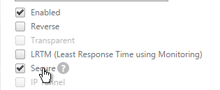
  • XenApp/XenDesktop must be licensed for Platinum Edition. This is only required for the Director integration. Without Platinum, you can still access the HDX Insight data by going visiting the NetScaler MAS website.
  • Director must be 7.11 or newer for NetScaler MAS support.
  • NetScaler MAS must be 11.1 build 49 or newer.

To link Citrix Director with NetScaler MAS, on the Director server, run C:\inetpub\wwwroot\Director\tools\DirectorConfig.exe /confignetscaler.

  1. Enter the NetScaler MAS nsroot credentials.
  2. If HTTPS Connection (recommended), the NetScaler MAS certificate must be valid and trusted by both the Director Server and the Director user’s browser.
  3. Enter 1 for NetScaler MAS.
  4. Do this on both Director servers.

Use NetScaler MAS

Marius Sandbu NetScaler Management and Analytics Systems has a quick rundown of the major features.

The AppFlow Analysis tools (e.g. HDX Insight) are located on the Analytics tab.

NetScaler MAS also includes all of the previous Command Center functionality, which you can find on the Infrastructure and Applications tabs. For example, on the Infrastructure tab, select an instance, and view its Dashboard.

Backups are available at View Backup.

Dave Bretty Automating Your Netscaler 11.1 Vserver Config Using Netscaler Management and Analytics System: use a Configuration Job to deploy StoreFront load balancing configuration to an instance.

On the Applications tab, Dashboard node, Applications sub-tab, you can click New Application to group vServers together so they can be monitored as a group.

Links:

HDX Insight

HDX Insight Dashboard displays ICA session details including the following:

  • WAN Latency
  • DC Latency
  • RTT (round trip time)
  • Retransmits
  • Application Launch Duration
  • Client Type/Version
  • Bandwidth
  • Licenses in use

HDX Insight can also display Geo Maps. Configure NetScaler MAS with Data Center definitions (private IP blocks). More info at Geo Maps for HDX Insight at Citrix Docs.

Gateway Insight

On the Analytics tab is Gateway Insight.

This feature displays the following details:

  • Gateway connection failures due to failed EPA scans, failed authentication, failed SSON, or failed application launches.
  • Bandwidth and Bytes Consumed for ICA and other applications accessed through Gateway.
  • # of users
  • Session Modes (clientless, VPN, ICA)
  • Client Operating Systems
  • Client Browsers

More details at Gateway Insight at Citrix Docs.

Security Insight

The Security Insight dashboard uses data from Application Firewall to display Threat Index (criticality of attack), Safety Index (how securely NetScaler is configured), and Actionable Information. More info at Security Insight at Citrix Docs.

Troubleshooting

Citrix CTX215130 HDX Insight Diagnostics and Troubleshooting Guide: Syslog messages; Error counters; Troubleshooting checklist, Logs

Citrix Blog PostNetScaler Insight Center – Tips, Troubleshooting and Upgrade

See docs.citrix.com Troubleshooting Tips. Here are sample issues covered in docs.citrix.com:

  • Can’t see records on Insight Center dashboard
  • ICA RTT metrics are incorrect
  • Can’t add NetScaler appliance to inventory
  • Geo maps not displaying

Upgrade NetScaler MAS

  1. Download the latest Upgrade Pack for NetScaler Management and Analytics System.
  2. Login to NetScaler MAS.
  3. On the System tab, on the left, click the System Administration node.
  4. On the right, in the right pane, click Upgrade NetScaler MAS.
  5. Browse to the Software Image Upgrade Pack .tgz file and click OK.
  6. Click Yes to reboot the appliance.
  7. After it reboots, login. The new firmware version will be displayed in the top right corner.

Citrix Federated Authentication Service (SAML) 2407

Last Modified: Aug 20, 2024 @ 8:55 am

Navigation

This article applies to Federated Authentication Service (FAS) versions 2407, 2402 LTSR CU1, 2203 LTSR CU5, 1912 LTSR CU9, and all other versions 7.9 and newer.

Change Log

Overview

Citrix Federated Authentication Service (FAS) enables users to log in to Citrix Gateway and Citrix StoreFront using SAML authentication.

With SAML, Citrix Gateway and StoreFront do not have access to the user’s password and thus cannot perform single sign-on to the VDA. FAS works around this limitation by using issuing certificates that can be used to logon to the VDA.

  • StoreFront asks Citrix Federated Authentication Service (FAS) to use a Microsoft Certificate Authority to issue Smart Card certificates on behalf of users.
  • The certificates are stored on the FAS server.
  • The VDA requests the user’s certificate from FAS so it can complete the VDA Windows logon process.

FAS can be used for any authentication scenario where the user’s password is not provided.

Requirements:

  • Microsoft Certification Authority (CA) in Enterprise mode.
    • When configuring FAS, you tell it what CA server to use.
    • You can build a new CA server just for FAS.
    • You can install CA on the FAS server.
  • Domain Controllers must have Domain Controller certificates. See CTX218941 FAS – Request not supported.
    • The certificates on the Domain Controllers must support smart card authentication. Certificates created using the Microsoft CA certificate template named Domain Controller Authentication supports smart cards. Manually created Domain Controller certificates might not work. See CTX270737 for the Domain Controller certificate requirements.

  • Citrix Virtual Apps and Desktops or XenApp/XenDesktop 7.9 or newer
  • StoreFront 3.6 or newer
  • Citrix Gateway.
    • StoreFront 3.9 and newer also support SAML authentication natively without Citrix ADC.
  • SAML in an nFactor (Authentication Virtual Server) configuration works in both browsers and Workspace app.
  • For multiple domains, see Deployment Guide: Multi-Domain FAS Architecture at Citrix Tech Zone.

Configuration overview:

  1. Build one or more FAS servers.
    • For security reasons, FAS should be its own server and not installed on a Delivery Controller.
  2. Upload Certificate Templates to Active Directory and configure a CA server to issue certificates using the new templates.
    • Enterprise Admin permissions are needed to upload the Certificate Templates.
    • One of the Certificate Templates is for Smart Card logon to Citrix VDA.
    • The other two Certificate Templates are to authorize FAS as a certificate registration authority.
    • The registration authority certificate does not renew automatically so be prepared to renew it manually every two years. See Renew registration authority certificates at Citrix Docs.
  3. Install the Citrix FAS group policy .admx template into PolicyDefinitions.
  4. Create a group policy object (GPO) and configure the GPO with the addresses of the FAS servers.
    • The GPO must apply to FAS servers, StoreFront servers, and every VDA. It does not need to apply to Delivery Controllers, but there’s no harm in applying it to the Delivery Controllers.
  5. Authorize FAS to request certificates from a Microsoft CA server.
  6. Configure FAS Rules to permit StoreFront servers to request FAS to generate certificates for users and permit VDA machines to retrieve the certificates from FAS.
  7. Configure StoreFront to use FAS for VDA single sign-on.

Links:

From Citrix CTX225721 Federated Authentication Service High Availability and Scalability: you can build multiple FAS servers. Enter all FAS server FQDNs in the Group Policy. StoreFront will then use a hashing algorithm on the username to select a FAS server.

  1. If you have less than 10K users, one FAS server with 4 vCPUs (2.5Ghz) should be sufficient.
  2. You will require a minimum of one FAS server (with 8 vCPUs) per 25,000 users if all users expect to be able to logon under cold start conditions (no keys or certificates cached) within 60-90 minutes.
  3. A single FAS server can handle greater than 50K users under warm start conditions (keys and certificates pre-cached)
  4. One reserve FAS server for every four FAS servers for “Day 1” cold start (Users get new keys/certificates) & disaster recovery scenarios
  5. Split the FAS Certificate Authority from Certificate Authority that performs other tasks for both security and scalability purposes.

Michael Shuster explains the Group Policy configuration for FAS in multiple datacenters at HowTo: Active-Active Multi-Datacenter Citrix FAS.

Also see the Citrix Federated Authentication Service Scalability whitepaper.

Federated Authentication Service Versions

The most recent Federated Authentication Service Current Release is version 2407.

For LTSR versions of Citrix Virtual Apps and Desktops (CVAD) and StoreFront, install the version of FAS that comes with the CVAD LTSR version.

Install/Upgrade Federated Authentication Service

The service should be installed on a secure, standalone server that does not have any other Citrix components installed. The FAS server stores user authentication keys, and thus security is paramount.

  1. On the Federated Authentication Service server, go to the Citrix Virtual Apps and Desktops, or XenDesktop 7.9, or newer ISO, and run AutoSelect.exe. Or you can download the standalone installer and run that.
  2. In the lower half of the window, click Federated Authentication Service.
  3. In the Licensing Agreement page, select I have read, understand, and accept the terms of the license agreement, and click Next.
  4. In the Core Components page, click Next.
  5. In the Firewall page, click Next.
  6. In the Summary page, click Install.
  7. The installer will probably ask for a restart.

    1. After the reboot, and after logging in again, you might see a Locate ‘Citrix Virtual Apps and Desktops 7’ installation media window. Don’t click anything yet.
    2. Go to the Citrix_Virtual_Apps_and_Desktops_7_2407_iso file and mount it.
    3. Go back to the Locate ‘Citrix Virtual Apps and Desktops 7’ installation media window.
    4. On the left, expand This PC, and click the DVD Drive.
    5. Click Select Folder.
  8. Click Finish.

FAS Group Policy

Configure a Group Policy that instructs StoreFront servers and VDAs on how to locate the FAS servers.

  1. On the Federated Authentication Service server, browse to C:\Program Files\Citrix\Federated Authentication Service\PolicyDefinitions. Copy the files and folder.
  2. Go to \\domain.com\SYSVOL\domain.com\Policies\PolicyDefinitions and paste the files and folder. If PolicyDefinitions doesn’t exist in SYSVOL, then copy them to C:\Windows\PolicyDefinitions instead.
  3. Edit a GPO that applies to all StoreFront servers, all Federated Authentication Service servers, and all VDAs.
  4. Navigate to Computer Configuration > Policies > Administrative Templates > Citrix Components > Authentication.
  5. Edit the setting Federated Authentication Service.
  6. Enable the setting and click Show.
  7. Enter the FQDN of the Federated Authentication Service server. You can add more than one Federated Authentication Service server.
  8. Click OK twice.
  9. On the Federated Authentication Service server, and VDAs, run gpupdate.
  10. On the FAS server, and on VDAs, look in the registry at HKLM\Software\Policies\Citrix\Authentication\UserCredentialService\Addresses. Make sure this key and value exists. The number one cause why FAS doesn’t work is because this key is missing from VDAs. The FAS Address GPO must apply to VDAs too.
  11. If the VDAs and Users are in different domains, see CTX220497 Users from one AD Domain not able to get FAS user certificates from another trusted domain: add the Citrix StoreFront Servers, FAS server and VDA servers to the Windows Authorization Access Group in the users’ domain. Also see Deployment Guide: Multi-Domain FAS Architecture at Citrix Tech Zone.
  12. By default, the VDAs will verify the certificates aren’t revoked by downloading the Certificate Revocation List. You can disable CRL checking by configuring HKEY_Local_Machine\System\CurrentControlSet\Control\LSA\Kerberos\Parameters\UseCachedCRLOnlyAndIgnoreRevocationUnknownErrors (DWORD) = 1 as detailed at CTX217150 Unable to login using the FAS Authentication – Getting Stuck on Please wait for local session manager.
  13. If your VDAs have third party credential providers (e.g., Duo), then it might interfere with FAS Single Sign-on.

FAS 1909+ Configuration

If you prefer to script the FAS configuration, then see Citrix Blog Post Automating the Citrix Federated Authentication Service with PowerShell.

FAS 1909 and newer have a different configuration GUI than FAS 1906 and older.

Here are 1909 and newer GUI configuration instructions:

  1. Log into the FAS server as an Enterprise Administrator that can upload certificate templates to Active Directory.
  2. On the FAS server, from the Start Menu, run Citrix Federated Authentication Service as administrator. Make sure you run it elevated.
  3. In the tab named Initial Setup, in the row named Deploy certificate templates, click Deploy.
  4. Click OK to deploy the templates to Active Directory.
  5. In the row named Set up a certificate authority, click Publish.
  6. Select an Enterprise Certificate Authority that will be issue the FAS certificates and click OK.
  7. In the row named Authorize this service, click Authorize.
  8. Select a CA that will issue this FAS server a Registration Authority certificate. Later, you will need to open the Certificate Authority console on the chosen server. Click OK.
  9. The row named Authorize this service has a new icon indicating it is waiting on the registration authority certificate to be approved.
  10. Open the Certification Authority console and point it to the CA server. In the Pending Requests node, find the certificate request for the FAS server and Issue it.
  11. Back in the FAS Administration Console, on the top right, click Refresh.
  12. The row named Authorize this service should now have a green check mark.
  13. In the row named Create a rule, click Create.
  14. In the Rule name page, leave it set to Create the default rule and click Next.
  15. In the Template page, click Next.
  16. In the Certificate authority page, select the CA that has the issuing templates configured and click Next. You can select more than one CA server.
  17. In the In-session use page, click Next.
  18. In the Access control page, click the link to Manage StoreFront access permissions.
  19. In the Permission for StoreFront Servers page, add your StoreFront servers and give them the permission Assert Identity. Click OK.
  20. Back in the Create Rule wizard, click Next.
  21. In the Restrictions page, you can optionally reduce the VDAs that are authorized to use FAS. Click Next.
  22. In the Summary page, click Create.
  23. The FAS Registration Authority certificate expires in two years. You’ll need to manually renew the FAS Registration Authority certificate before it expires. Put a notification on your calendar. For details, see Renew registration authority certificates at Citrix Docs.
    • In the row named Authorize this service, you can click the link for authorization certificate to see when it expires. Before expiration, use the Reauthorize button on the right of the same row.
  24. Jump ahead to Certificate Templates.

FAS 1906 and older Configuration

If you prefer to script the FAS configuration, then see Citrix Blog Post Automating the Citrix Federated Authentication Service with PowerShell.

Here are GUI configuration instructions for FAS 1906 and older:

  1. Log into the FAS server as a Domain Administrator or Enterprise Administrator that can upload certificate templates to Active Directory.
  2. On the FAS server, from the Start Menu, run Citrix Federated Authentication Service as administrator. Make sure you run it elevated.
  3. The Federated Authentication Service FQDN should already be in the list (from group policy). Click OK.
  4. In Step 1: Deploy certificate templates, click Start.
  5. Click OK to add certificate templates to Active Directory. Sufficient permission is required.
  6. In Step 2: Setup Certificate Authority, click Start.
  7. Select a Certificate Authority to issue the certificates, and click Ok.
  8. In Step 3: Authorize this Service, click Start.

    • Step 3 automatically submits an online request for the Registration Authority certificate to the CA and stores the non-exportable private key in the standard Microsoft Enhanced RSA and AES Cryptographic Provider.
    • Alternatively, you can submit the certificate request manually, and store the private key in TPM or HSM as detailed at Federated Authentication Service private key protection at Citrix Docs. When running New-FasAuthorizationCertificateRequest, the -UseTPM switch is optional.
  9. Select the issuing Certificate Authority, and click OK.

    • Authorize this Service only lets you select one Certificate Authority. If you want to load balance certificate requests against multiple Certificate Authorities, then see Set up multiple CA servers for use in FAS at Citrix Docs.
      Set-FasCertificateDefinition -Name default_Definition -CertificateAuthorities @("ca1.corp.local\CA1.corp.local", "ca2.corp.local\ca2.corp.local")
  10. Step 3 is now yellow.
  11. On the Microsoft CA server, go to the Certification Authority Console > Pending Requests. Find the pending request, and Issue it.
  12. In a minute or two, Federated Authentication Service will recognize the issued certificate and Step 3 will turn green.
  13. After FAS authorization with the CA, in the FAS Configuration tool, switch to the User Rules tab.
  14. Use the Certificate Authority drop-down to select the issuing Certificate Authority.
  15. Use the Certificate Template drop-down to select the Citrix_SmartcardLogon template.
  16. Click Edit next to List of StoreFront servers that can use this rule.
  17. Remove Domain Computers from the top half, and instead add your StoreFront servers. You could add an Active Directory security group instead of individual StoreFront servers.
  18. On the bottom half, make sure Assert Identity is Allowed. Click OK.
  19. By default, all users and all VDAs are allowed. You can click the other two Edit boxes to change this.
  20. When done, click Apply.
  21. Click OK when you see Rule updated successfully.
  22. The FAS Registration Authority certificate expires in two years. You’ll need to manually renew the FAS Registration Authority certificate before it expires. Put a notification on your calendar. For details, see Renew registration authority certificates at Citrix Docs.
    • To see the expiration date of the authorization certificate, run the following PowerShell command after running add-pssnapin Citrix.Authentication.FederatedAuthenticationService.V1:
      Get-FasAuthorizationCertificate -FullCertInfo -address myFASServer

Certificate Templates

The deployed FAS Certificate Templates from older versions of FAS have Autoenroll enabled. Newer versions of FAS (e.g., 2203) no longer have Autoenroll enabled.

  1. Open the Certificate Templates console. One option is to open the Certification Authority console, right-click Certificate Templates, and then click Manage.
  2. There should be three templates with names starting with Citrix_. Open the properties on each one.
  3. On the Security tab, highlight each group assigned to the template.
  4. On the bottom half, uncheck the box in the Autoenroll row but leave Enroll checked. Perform this step for every group assigned to this template. Then click OK.
  5. Repeat disabling autoenroll for the other two templates.

The Registration Authority certificate templates are permitted to all Domain Computers. You might want to change that.

  1. Open the Properties of one of the Citrix_RegistrationAuthority certificate templates.
  2. On the Security tab, remove Domain Computers.
  3. Add your FAS servers and enable the Enroll permission.
  4. Repeat for the other Registration Authority certificate.

To further restrict who can be issued certificates, go to your Certificate Authority’s Properties and use the Enrollment Agents tab to restrict enrollment agents.

StoreFront Configuration

Once FAS is enabled on a StoreFront store, it applies to all connections through that store, including password-based authentications. One option is to create a new store just for FAS users.

  1. Check the registry at at HKLM\Software\Policies\Citrix\Authentication\UserCredentialService\Addresses to confirm that the group policy with FAS addresses has been applied to the StoreFront servers.
  2. On the StoreFront 3.6 or newer server, run the following elevated PowerShell command:
    & "$Env:PROGRAMFILES\Citrix\Receiver StoreFront\Scripts\ImportModules.ps1"
  3. Run the following commands. Adjust the store name as required.
    $StoreVirtualPath = "/Citrix/Store"
    $store = Get-STFStoreService -VirtualPath $StoreVirtualPath
    $auth = Get-STFAuthenticationService -StoreService $store
    Set-STFClaimsFactoryNames -AuthenticationService $auth -ClaimsFactoryName "FASClaimsFactory"
    Set-STFStoreLaunchOptions -StoreService $store -VdaLogonDataProvider "FASLogonDataProvider"
  4. If you have multiple StoreFront servers, Propagate Changes.
  5. In Web Studio (CVAD 2212 and newer), go to Settings and Enable XML Trust.

    • Or on a Citrix Delivery Controller, run the following PowerShell command:
      Set-BrokerSite -TrustRequestsSentToTheXmlServicePort $true

If you ever need to disable FAS on StoreFront, run the following commands. Adjust the store name as required.

$StoreVirtualPath = "/Citrix/Store"
$store = Get-STFStoreService -VirtualPath $StoreVirtualPath
$auth = Get-STFAuthenticationService -StoreService $store
Set-STFClaimsFactoryNames -AuthenticationService $auth -ClaimsFactoryName "standardClaimsFactory"
Set-STFStoreLaunchOptions -StoreService $store -VdaLogonDataProvider ""

SAML Configuration

SAML Flow

SAML flows like this:

  1. (Optional) User goes to the web application aka Service Provider (e.g. Citrix Gateway).
    • The Service Provider (SP) redirects the user’s browser to the Identity Provider’s (IdP) SAML Single Sign-on (SSO) URL and includes an authentication request in the Redirect. The IdP SSO URL might be different for each Service Provider.
    • The Authentication Request from the Service Provider includes a Service Provider Entity ID. The IdP matches the SP Entity ID with an entry in its database so it knows which SP is making the authentication request. The Entity ID must match on both the SP and the IdP.
    • If the Authentication Request is signed by the Service Provider’s certificate private key, then the IdP will verify the signature using the Service Provider’s certificate public key. In this scenario, the Service Provider’s certificate (without private key) must be loaded into the IdP.
  2. The user authenticates to the IdP, typically using Multi-factor Authentication.
    • If the user was redirected from the SP, then the IdP already knows which SP to authenticate with.
    • If the user went directly to the IdP, then the user typically needs to click an icon representing the web application (Service Provider).
  3. IdP generates a SAML Assertion containing the user’s userPrincipalName or email address.
    • Configure the IdP to include the user’s UPN or email address in the NameID field of the assertion. SAMAccountName won’t work with Citrix FAS.
    • The SAML Assertion also includes the Service Provider’s Entity ID. The ID in the Assertion must match the ID configured on the SP.
    • IdP signs the SAML Assertion using an IdP certificate private key.
    • IdP has a configuration for the SP that includes a SAML Assertion Consumer Service (ACS) URL. IdP redirects the user’s browser to the SP’s ACS URL and POST’s the SAML Assertion.
      • The ACS URL on Citrix Gateway ends in /cgi/samlauth
  4. SP uses the IdP certificate’s public key to verify the signature on the SAML Assertion.
    • The IdP’s certificate (without private key) is installed on the Citrix ADC so it can verify the Assertion’s signature.
  5. SP extracts the user’s userPrincipalName from the Assertion and uses the UPN for Single Sign-on to StoreFront and the rest of the Citrix components.
    • Note that the SP does not have access to the user’s password and thus that’s why we need Citrix FAS to generate certificates for each user.

Configure the SAML IdP

You typically start the configuration on the Identity Provider (IdP). Every IdP has unique instructions. Search Google for your IdP and Citrix ADC and you might find a IdP-specific guide. After IdP configuration, you download the IdP’s certificate and copy the IdP’s SSO URL so you can configure them on Citrix ADC.

Azure AD as SAML IdP

  1. In Azure Portal, go to Azure Active Directory.
  2. On the left, click Enterprise applications.
  3. In the new blade that appears, on the All applications page, on the right, click New application.
  4. In the All Categories view of the gallery, on the top right, click Non-gallery application.
  5. Give the application a descriptive name. Azure AD shows this name in the myapps portal. Click Add.
  6. After the application is created, on the left, in the Manage section, click Single sign-on.
  7. On the right, click the big button for SAML.
  8. In section 1 labelled Basic SAML Configuration, click the pencil icon.
  9. In the Identifier (Entity ID) field, enter an identifier in URI format. Usually it matches the FQDN of the Citrix Gateway and can be entered in https://gateway.corp.com format. You’ll later need to specify the exact same Identifier on the Citrix ADC.
  10. In the Reply URL (Assertion Consumer Service URL) field, enter a URL similar to https://mygateway.company.com/cgi/samlauth. The path must be /cgi/samlauth. The scheme should be https. And the FQDN is your Citrix Gateway’s FQDN.
  11. Click Save. Then you might have to click the x on the top right to make it go away.
  12. In section 2 labelled User Attributes & Claims, notice that it defaults to sending the userprincipalname. You can click the pencil to change the attribute used for the Name identifier value. Whatever value you send will need to match the userPrincipalNames of local Active Directory accounts (aka shadow accounts).


  13. In section 3 labelled SAML Signing Certificate, click the Download link in the Certificate (Base64) line.
  14. Citrix ADC 12.1 and newer support SAML metadata so feel free to copy the App Federation Metadata Url field.
  15. If you are running NetScaler 12.0 or older, then you will need to copy the Login URL field from section 4 labelled Set up gateway5.corp.com
  16. On the left, under Manage, click Users and groups.
  17. Use the normal process to assign Azure AD users and groups to this application. Click Assign.
  18. Jump to the section named Citrix ADC SAML Configuration.

ADFS as SAML IdP

The screenshots in this section use ADFS as an example IdP. Your IdP will be different.

  1. In your SAML IdP, create a Relying Party Trust (aka service provider trust) or new Application.
  2. Since we’re configuring the IdP before we configure Citrix ADC and thus don’t have access to the SP metadata, select the option to Enter data about the relying party manually.
  3. For the Assertion Consumer Service URL (aka relying party service URL), enter the URL to your Citrix Gateway with /cgi/samlauth appended to the end (e.g. https://gateway.corp.com/cgi/samlauth)
  4. Enter a Relying party trust identifier in URI format. You must specify the same identifier (Issuer Name) on the Citrix ADC as detailed in the next section.
  5. Configure the SAML IdP to send email address or User-Principal-name as Name ID. Citrix ADC receives the Name ID and sends it to StoreFront. StoreFront will look in Active Directory for an account with userPrincipalName that matches the Name ID.
  6. Citrix ADC will sign the authentication requests it sends to the IdP. On the Citrix ADC, you will soon configure the Citrix ADC SAML SP signing certificate with private key that signs the authentication requests that are sent to the IdP. In your SAML IdP, import the same Citrix ADC SAML SP signing certificate but without the private key.
  7. Copy the SAML authentication URL (aka Token Issuance URL) from your SAML IdP. You’ll need to enter this same URL on your Citrix ADC later.
  8. Export the IdP Token-signing certificate from your SAML IdP. The IdP could be ADFS, Okta, Ping, etc.

Citrix ADC SAML Configuration

SAML Server/Action

  1. Instructions for Citrix ADC 13.0, Citrix ADC 12.1, NetScaler 12.0, and NetScaler 11.1 are essentially the same.
    • Citrix ADC 12.1 and newer support SAML Metadata while older versions of NetScaler do not support SAML Metadata.
    • NetScaler 11 is very similar, except Certificates are in a different place in the NetScaler menu tree.
  2. Workspace app support – If you bind a SAML Authentication Policy directly to the Gateway Virtual Server (no nFactor/AAA), then Workspace app and Gateway VPN plug-in won’t work. To support SAML with Workspace app and Gateway VPN plug-in, configure nFactor (Authentication Virtual Server with Authentication Profile) instead of directly on the Gateway Virtual Server.
  3. IdP Signing Certificate – On Citrix ADC, if you are not importing IdP metadata, then manually import the IdP SAML token-signing certificate (without private key) under Traffic Management > SSL > Certificates > CA Certificates. Citrix ADC uses this certificate to verify the signature of the SAML assertion from the IdP.
    Note: when you later create the SAML Action on Citrix ADC, there’s a place to add a SAML certificate. Unfortunately, the SAML Action is trying to import the wrong type of certificate since it wants the private key, which you don’t have access to. If you import the certificate here under CA Certificates, then there’s no prompt for private key.


    • SAML IdP certificates are shown in the Unknown Certificates node.
  4. If you want ADC to sign the authentication requests it sends to the IdP, then do the following:
    1. Move up two nodes to Server Certificates and Import or create a SP SAML signing certificate with private key. This can be the same certificate used on Citrix Gateway. Or a more common practice is to create a self-signed certificate.

    2. You’ll also need to import this SAML SP signing certificate (without private key) to your SAML IdP so it can verify the SAML authentication request signature from the Citrix ADC.
  5. Go to Citrix Gateway > Policies > Authentication > SAML. The quickest way to get here is to enter SAML in the search box on top of the menu.
  6. On the right, switch to the tab labelled Servers, and click Add.
  7. In the Name field, give the SAML Action a name that indicates the IdP’s name.
  8. If your Citrix ADC is 12.1 or newer, then get the SAML Metadata URL (or file) from the IdP.

    1. In the SAML Server on Citrix ADC, in the SAML IDP Metadata URL field, paste in the URL. ADC should be able to extract the IdP’s certificate from the Metadata URL.
    2. In the Issuer Name field, enter the ID that the SAML IdP is expecting for the Relying Party.  This Issuer Name must match the name you configured on the IdP’s Relying Party (Service Provider) Trust. Azure AD calls this the Identifier or Entity ID.
    3. Near the bottom, configure a Relay State Rule to prevent session hijack. It should check the Relay State field to make sure it matches the URL that users using to reach the Gateway Virtual Server. Make sure you include the forward slash at the end of the URL. Sample expression below. Pattern set is also possible. See CTX316577 for details. To avoid relay state “does not match” error, make sure users enter the Gateway URL instead of using a bookmark. 💡
      AAA.LOGIN.RELAYSTATE.EQ("https://gateway5.corp.com/")

    4. Scroll down and click More.
    5. You can optionally check Force Authentication to prevent users from doing SAML authentication using cached credentials. This prompts for MFA every time the user accesses Citrix Gateway.
    6. Scroll down and click Create.
    7. Edit the SAML Server again.
    8. If you uncheck the box next to Import Metadata, you can see the fields that it filled in for you. Unfortunately, other fields must be configured manually as detailed soon.
  9. Configure the SAML Server based on the data provided by your IdP. If you imported Metadata, then some of the fields might already be populated.
    1. For IDP Certificate Name, select the SAML IdP’s certificate that was exported from the SAML IdP and imported to Citrix ADC. Citrix ADC will use this IdP certificate to verify SAML assertions from the IdP.
      Note: the Add button here does not work correctly. Instead, if you need to import the SAML IDP certificate, then do it at the CA Certificates node as detailed earlier in this section.
    2. For Redirect URL, enter the URL to the SAML IdP’s authentication page. Citrix Gateway will redirect users to this URL. For ADFS, enter your ADFS URL appended with /adfs/ls (e.g. https://adfs.corp.com/adfs/ls). For other IdP’s, get the URL from your IdP.
    3. For User Field, enter the name of the SAML Claim from the IdP that contains the value that matches the userPrincipalName of your local Active Directory users (aka shadow accounts). This defaults to the NameID field, but you might have to use a different claim, like emailaddress.
    4. In the Issuer Name field, enter the ID that the SAML IdP is expecting for the Relying Party.  This Issuer Name must match the name you configured on the IdP’s Relying Party (Service Provider) Trust. Azure AD calls this the Identifier or Entity ID.
    5. Near the bottom, configure a Relay State Rule to prevent session hijack. It should check the Relay State field to make sure it matches the URL that users using to reach the Gateway Virtual Server. Make sure you include the forward slash at the end of the URL. Sample expression below. Pattern set is also possible. See CTX316577 for details. 💡
    6. Optionally, for Signing Certificate Name, select the SAML SP certificate (with private key) that Citrix ADC will use to sign authentication requests to the IdP. This same certificate (without private key) must be imported to the IdP, so the IdP can verify the authentication request signature. This field usually isn’t needed by most IdPs.
    7. Scroll down and click More.
    8. Citrix ADC defaults to SHA1. You might have to change the Signature Algorithm and Digest Method to SHA256.
    9. Review the other settings as needed by your IdP. Click Create when done.

SAML Policy – Advanced (nFactor) Method

Workspace app and Gateway Plugin (i.e. VPN plugin) require nFactor (Advanced Authentication Policies) to support SAML authentication.

Licensing – nFactor requires NetScaler ADC Advanced Edition or NetScaler ADC Premium Edition. The newest builds of NetScaler ADC 13 have added nFactor support for NetScaler ADC Standard Edition, but the configuration of an Authentication Virtual Server is not directly accessible from the main menu. If you only have Standard Edition, then do the following to get to the Authentication Virtual Server:

  1. Go to Citrix Gateway > Virtual Servers and edit one.
  2. On the right, add the Authentication Profile section.
  3. On the left, in the Authentication Profile section, click Add to create an Authentication Profile.
  4. In the Authentication Virtual Server row, click Add to create an Authentication Virtual Server.
  5. The rest of the nFactor configuration is similar to what’s detailed below.

If you prefer to configure the older Classic Method, which doesn’t work with Workspace app, then skip to the Classic Method.

Do the following to create an Advanced Authentication Policy, an Authentication Virtual Server, and bind it to the Gateway Virtual Server:

  1. In the left menu, expand Security, expand AAA – Application Traffic, expand Policies, expand Authentication, expand Advanced Policies, and then click Policy.
  2. On the right, click the button labelled Add.

    1. Change the drop-down for Action Type to SAML.
    2. Change the drop-down for Action to the SAML Action you created earlier.
    3. In the box labelled Expression, enter true.
    4. Give the policy a name and click Create.
  3. In the left menu, expand Security, expand AAA – Application Traffic and then click Virtual Servers.
  4. On the right, click the button labelled Add.

    1. Change the drop-down named IP Address Type to Non Addressable and then click OK.
  5. You can optionally bind a Server Certificate. If you don’t bind a certificate, then the AAA vServer will be down but it will still work. It doesn’t matter what certificate you choose. Click Continue when done.
  6. On the left, in the section named Advanced Authentication Policies, click the row that says No Authentication Policy.

    1. Click where it says Click to select.
    2. Click the small circle to the left of the SAML Policy that you created earlier. Then click the blue button labelled Select at the top of the screen.
    3. There’s no need to configure Select Next Factor unless you want to bind an LDAP Policy with Authentication Disabled so you can extract groups from Active Directory and use those groups for Gateway authorization. This configuration procedure is detailed in the next section.
    4. Click the blue button labelled Bind at the bottom of the window.
  7. Click Continue,
  8. At the bottom of the page, click Done to finish creating the AAA vServer.
  9. In the left menu, expand Citrix Gateway and click Virtual Servers.
  10. On the right, edit your existing Gateway Virtual Server.
  11. On the right side of the screen, in the Advanced Settings column, click Authentication Profile.
  12. On the left side of the screen, find the Authentication Profile section and then click the button labelled Add.
  13. Click where it says Click to Select and then select your AAA vServer.
  14. Give the Authentication Profile a name and then click the blue button named Create.
  15. Make sure you click the blue OK button before you click Done. If you don’t click OK then your changes won’t be saved.

Here are some sample CLI commands for this nFactor SAML configuration.

# SAML Actions
# ------------
add authentication samlAction "Azure AD" -samlIdPCertName AzureADSAML -samlSigningCertName WildcardCorpCom -samlRedirectUrl "https://login.microsoftonline.com/815e26a9-4a9b/saml2" -samlIssuerName gateway5.corp.com -Attribute1 emailaddress -logoutURL "https://login.microsoftonline.com/815e26a9/saml2" -logoutBinding REDIRECT -relaystateRule "aaa.LOGIN.RELAYSTATE.EQ(\"https://gateway5.corp.com/\")"

# SAML Authentication Policies
# ----------------------------
add authentication samlPolicy "Azure AD" ns_true "Azure AD"

# Advanced Authentication Policies
# --------------------------------
add authentication Policy "Azure AD Advanced" -rule true -action "Azure AD"

# Authentication Virtual Servers
# ------------------------------
add authentication vserver nFactor-AzureAD-SAML SSL 0.0.0.0
bind authentication vserver nFactor-AzureAD-SAML -policy "Azure AD Advanced" -priority 100 -gotoPriorityExpression NEXT

# Authentication Profiles
# -----------------------
add authentication authnProfile nFactor-AzureAD-SAML -authnVsName nFactor-AzureAD-SAML

# Citrix Gateway Virtual Servers
# ------------------------------
set vpn vserver gateway5.corp.com -authnProfile nFactor-AzureAD-SAML

SAML nFactor LDAP Group Extraction

If you use AAA Groups with Citrix Gateway, then be aware that SAML usually does not provide the user’s group membership. Instead, configure a LDAP Policy to get the user’s groups from Active Directory so the groups can be later used by Citrix Gateway.

If you don’t need LDAP Group Extraction, then skip ahead to the StoreFront section.

Do the following to configure LDAP Group Extraction.

  1. Create a new LDAP Action.
    1. Use the Search in Menu to find LDAP then pick any of the results.
    2. Check the box next to an existing LDAP policy and click Add to copy its configuration. Or create a new one.
    3. Change the name of the LDAP Action.
    4. On the top right, uncheck the box next to Authentication.
    5. Scroll down a bit and in the right side re-enter the Administrator Password. Copying an existing LDAP Action does not copy the Bind password.
    6. Scroll down to the Other Settings section.
    7. On the left, change Server Logon Name Attribute to –<< New >>–.
    8. Enter userPrincipalName. The UPN is extracted from the SAML Assertion.
    9. Scroll down and click Create.
  2. On the left, go to Security > AAA – Application Traffic > Policies > Authentication > Advanced Policies > Policy and click Add to create a new Policy.

    1. Change Action Type to LDAP.
    2. Expression = true.
    3. Click Create.
  3. On the left, go to Security > AAA – Application Traffic > Policies > Authentication > Advanced Policies > Policy Label. On the right, click Add.

    1. Give the Policy Label a name and click Continue. The Login Schema should be LSCHEMA_INT.
    2. Select your LDAP Group Extract policy and then on the bottom click Bind.
    3. Click Done to close the Policy Label.
  4. On the left, go to Security > AAA – Application Traffic > Virtual Servers. On the right, edit your SAML AAA vServer.

    1. Click where it says 1 Authentication Policy.
    2. Right-click the Authentication Policy and then click Edit Binding.
    3. In the Select Next Factor field, click where it says Click to select.
    4. Select your LDAP Group Extract Policy Label and then click Bind.
  5. Skip ahead to the StoreFront section.

Here are some sample CLI commands for this nFactor SAML LDAP Group Extract configuration.

# LDAP Actions
# ------------
add authentication ldapAction LDAP-GroupExtract -serverIP 10.2.2.11 -serverPort 636 -ldapBase "dc=corp,dc=local" -ldapBindDn ctxsvc@corp.local -ldapBindDnPassword ****** -ldapLoginName userPrincipalName -groupAttrName memberOf -subAttributeName cn -secType SSL -authentication DISABLED

# LDAP Policies
# -------------
add authentication ldapPolicy LDAP-Corp ns_true LDAP-Corp

# Authentication Policy Labels
# ----------------------------
add authentication policylabel LDAP-GroupExtract -loginSchema LSCHEMA_INT
bind authentication policylabel LDAP-GroupExtract -policyName LDAP-GroupExtract -priority 100 -gotoPriorityExpression NEXT

# Authentication Virtual Servers
# ------------------------------
bind authentication vserver nFactor-AzureAD-SAML -policy "Azure AD Advanced" -priority 100 -nextFactor LDAP-GroupExtract -gotoPriorityExpression NEXT

Configure StoreFront for SAML Citrix Gateway

  1. In StoreFront 3.6 or newer, in the StoreFront Console, go to Stores, right-click the store, and click Manage Authentication Methods.
  2. Make sure Pass-through from Citrix Gateway is selected.
  3. Click the bottom gear icon on the right, and click Configure Delegated Authentication.
  4. Check the box next to Fully delegate credential validation to Citrix Gateway and click OK twice.
  5. In StoreFront, add a Citrix Gateway object that matches the FQDN of the Citrix Gateway Virtual Server that has SAML enabled.
  6. On the Authentication Settings page, make sure you configure a Callback URL. It won’t work without it.
  7. Then assign (Configure Remote Access Settings) the Gateway to your Store.

  8. Next step: create Active Directory Shadow Accounts

Native SAML on StoreFront without Citrix ADC

StoreFront 3.9 and newer have native support for SAML Authentication without Citrix ADC. Notes:

  • SAML overrides Explicit and Pass-through authentication.
  • SAML in StoreFront without Citrix ADC seems to work in Workspace app and Receiver Self-Service for Windows.

For an example configuration using StoreFront PowerShell commands and SAML metadata, see CTX232042 Configure StoreFront with OKTA.

To configure native SAML in StoreFront 3.9 or newer:

  1. Export the signing certificate from your SAML IdP. The IdP could be ADFS, Okta, Ping Identity, etc.
  2. In StoreFront 3.9 or newer console, right-click a Store, and click Manage Authentication Methods.
  3. Check the box next to SAML Authentication. If you don’t see this option (because you upgraded from an older version), click the Advanced button on the bottom of the window, and install the authentication method.
  4. On the right, click the gear icon for SAML, and click Identity Provider.
  5. Change the SAML Binding to the method your IdP expects.
  6. Enter the IdP token issuance endpoint URL. For example, in ADFS, the path is /adfs/ls.
  7.  Click Import.
  8. Browse to the signing certificate exported from your IdP, and click Open.
  9. Then click OK to close the Identity Provider window.
  10. On the right, in the SAML Authentication row, click the gear icon, and then click Service Provider.
  11. Click the first Browse button.
  12. Give the Signing certificate a name, and save it somewhere.
  13. Click the second Browse button.
  14. Give the Encryption certificate a name, and save it somewhere.
  15. Copy the Service Provider Identifier. Or you can change it to your desired value. Then click OK.
  16. In your IdP (e.g. ADFS), create a Relying Party Trust.
  17. Import the Encryption certificate that you exported from StoreFront.
  18. Enable SAML 2.0.
  19. For the Assertion Consumer Service (ACS) path, enter something similar to https://storefront.corp.com/Citrix/StoreAuth/SamlForms/AssertionConsumerService. The hostname portion of the URL is equivalent to your StoreFront Base URL. /Citrix/StoreAuth matches your Store name with Auth on the end. The rest of the path must be /SamlForms/AssertionConsumerService. You can get this ACS value by looking in the SAML metadata at the bottom of https://<storefront host>/Citrix/StoreAuth/SamlForms/ServiceProvider/Metadata.

  20. For the Relying party trust identifier, enter the identifier you copied from the Service Provider window in StoreFront.
  21. Configure the Claim Rules to send the user’s email address or userPrincipalName as Name ID.
  22. Edit the Relying Party Trust. Import the Signing certificate that you exported from StoreFront.

  23. Create Active Directory Shadow Accounts. Federated users must be userPrincipalName mapped to local Active Directory accounts.
  24. If you point your browser to https://<storefront-host>/Citrix/<storename>Auth/SamlTest, it should perform a SAML Login, and then show you the assertion that was returned from the IdP. See Citrix CTX220639 How to configure SAML Authentication-Test Configuration.
  25. See Citrix CTX220682 Storefront SAML Troubleshooting Guide for event logs, SAML Metadata, Active Directory account mapping, Trust XML, etc.
  26. When you go to your Receiver for Web page, it should automatically redirect you to your IdP. After authentication, it should redirect you back to StoreFront and show you your icons.
  27. ADFS also works in Receiver 4.6 and newer, and Workspace app.
  28. When you logoff, it won’t let you log on again unless you close your browser and reopen it.

  29. To fix this problem, see CTP Sacha Thomet StoreFront – Allow relogin without browser close. Edit the file C:\inetpub\wwwroot\Citrix\StoreWeb\custom\script.js, and add the following line:
    CTXS.allowReloginWithoutBrowserClose = true

  30. Now when you logoff, you’re given an option to log on again.

Active Directory Shadow Accounts

To login to Windows (Citrix VDA), every user must have an Active Directory account in a domain trusted by the VDA. For Federated Users, you typically need to create shadow accounts for each Federated user in your local Active Directory. These Shadow accounts need a userPrincipalName that matches the SAML attribute (usually email address) provided by the SAML IdP.

If the email address provided by the SAML IdP does not match the UPN suffix for your domain, then do the following:

  1. Open Active Directory Domains and Trust.
  2. Right-click the top left node (not a domain node), and click Properties.
  3. In the UPN Suffixes tab, add a UPN suffix that matches the email suffix provided by the SAML IdP.
  4. When creating a shadow account in your Active Directory, the new UPN suffix is available in the drop-down list. Note that the pre-Windows 2000 logon name can’t conflict with any other user in the domain.
  5. The password for these Shadow accounts can be any random complex password since the Federated users never need the Shadow account’s password.
  6. If the shadow account is already created, edit the account, and on the Account tab, use the drop-down to select the new UPN suffix.
  7. Create a shadow account for every federated user. There are third party Identity Management tools that can automate this. Or get an export from the IdP and use PowerShell scripting to create the acccounts.

Verify FAS

When FAS is enabled on StoreFront, every user that logs into StoreFront (local or remote) causes a user certificate to be created on the FAS server. You can see these user certificates by running the following PowerShell commands:

Add-PSSnapin Citrix.Authentication.FederatedAuthenticationService.V1
Get-FasUserCertificate -address fas01.corp.local

Citrix uses these certificates to logon to the VDA as the user. No password needed.

NetScaler 11.1 System Configuration

Last Modified: Jan 15, 2021 @ 6:23 am

Navigation

💡 = Recently Updated

Change Log

VPX Hardware

NetScaler VPX Release 11.1 supports new VPX models on ESXi. These new models include: VPX 25, VPX 5G, VPX 25G, etc. See the NetScaler VPX datasheet for more info.

NetScaler VPX Release 11.1 also supports changing the NIC type to VMXNET3 or SR-IOV. The imported appliance comes with E1000 NICs so you’ll have to remove all of the existing virtual NICs and add new VMXNET3 NICs.

Power On VPX and configure NSIP

  1. After swapping out the NICs to VMXNET3, power on the NetScaler VPX appliance.
  2. Configure the management IP from the VM’s console.
  3. Then point your browser to the management IP using either http or https and login as nsroot with password nsroot.

Auto-Provision IP Address

When importing VPX into a hypervisor, you can use VM advanced configuration parameters to set the NSIP. See CTX128250 How to Auto-Provision NetScaler VPX Appliance on a VMware ESX or ESXi Host, and CTX128236 How To Auto-Provision NetScaler VPX on XenServer.

Customer User Experience Improvement Program

  1. You might be prompted to enable the Customer User Experience Improvement Program. Either click Enable, or click Skip.

  2. You can also enable or disable the Customer Experience Improvement Program by going to System > Settings.
  3. On the right is Change CUXIP Settings.
  4. Make your selection and click OK.
  5. See https://www.carlstalhood.com/delivery-controller-7-15-ltsr-and-licensing/#ceip for additional places where CEIP is enabled.
set system parameter -doppler ENABLED

Welcome Wizard

NetScaler has a Welcome! Wizard that lets you set the NSIP, hostname, DNS, licensing, etc. It appears automatically the first time you login.

  1. Click the Subnet IP Address box.
  2. You can either enter a SNIP for one of your production interfaces, or you can click Do it later, and add SNIPs later after you configure Port Channels and VLANs. Note: If you have a dedicated management network, to prevent it from being used for outgoing traffic, don’t put a SNIP on it.

    add ns ip 10.2.2.60 255.255.255.0 -type SNIP
  3. Click the Host Name, DNS IP Address, and Time Zone box.
  4. Enter a hostname. Your NetScaler Gateway Universal licenses are allocated to this hostname. In a High Availability pair each node can have a different hostname. You typically create a DNS record that resolves the hostname to the NSIP (management IP).
  5. Enter one or more DNS Server IP addresses. Use the plus icon on the right to add more servers.
  6. Change the time zone to GMT-05:00-CDT-America/Chicago or similar.
  7. Click Done.

    set ns hostname ns02
    
    add dns nameServer 10.2.2.11
    
    set ns param -timezone "GMT-05:00-CDT-America/Chicago"
  8. Click Yes to save and reboot.
  9. Click the Licenses box.
  10. On the far right side of the screen, you’ll see the Host ID. You’ll need this to allocate your licenses at citrix.com. See below for detailed instructions on how to allocate the license to this Host ID.
  11. On the left, select Upload license files, and click Browse.
  12. Browse to the license file, open it, and click Reboot when prompted.
  13. After the reboot and logging in, a box will pop up showing you the installed license.
  14. Also look in the top left corner to make sure it doesn’t say NetScaler VPX (1). The number in the parentheses should match the MPX or VPX model number.

    License files are stored in /nsconfig/license.

Licensing – VPX Mac Address

To license a NetScaler VPX appliance, you will need its MAC address.

  1. Go to the Configuration tab.
  2. In the right pane, look down for the Host Id field. This is the MAC address you need for license allocation.
  3. Another option is to SSH to the appliance and run shell.
  4. Then run lmutil lmhostid. The MAC address is returned.

Licensing – Citrix.com

  1. Login to http://mycitrix.com.
  2. On the left, click All Licensing Tools.
  3. On the right, in the top right horizontal menu, click Activate and Allocate Licenses.
  4. If you are activating an eval license, click Don’t see your product near the top, and enter the eval license key.

  5. Otherwise, check the box next to a Citrix NetScaler VPX or MPX license, and click Continue.
  6. If this is a NetScaler MPX license then there is no need to enter a host ID for this license. so just click Continue.
  7. If this is a NetScaler VPX license, enter the VPX MAC address into the Host ID field. It’s not obvious, but you can enter text in this drop-down field.
  8. If you have more than one VPX license, change the Quantity field to 1, and then click Continue.

    For a VPX appliance, you can get the Host ID by looking at the System Information page. Click the System node to see this page.
  9. Click Confirm.
  10. Click OK when asked to download the license file.
  11. Click Download.
  12. Click Save and put it somewhere where you can get to it later.
  13. If you are running NetScaler 11.1 build 51 or newer, then 500 or more NetScaler Gateway Universal Licenses are already included in your NetScaler platform license. NetScaler Standard comes with 500 Gateway Universal, NetScaler Enterprise comes with 1,000 Gateway Universal, and NetScaler Platinum comes with unlimited Gateway Universal.
  14. If you need more Gateway Universal licenses on your NetScaler, you can allocate them now. These licenses can come from XenMobile Enterprise, XenApp/XenDesktop Platinum Edition, NetScaler Platinum Edition, or a la carte.
  15. Enter your appliance hostname as the Host ID for all licenses. If you have two appliances in a HA pair, allocate these licenses to the first appliance hostname, then reallocate them to the second appliance hostname.
  16. Click Confirm.
  17. Click OK when prompted to download your license file.
  18. Click Download.
  19. Click Save.
  20. If you have two appliances in a High Availability pair with different hostnames then you will need to return the NetScaler Gateway Universal licenses and reallocate them to the other hostname. The top right horizontal menu bar has a Reallocate option.

Install Licenses on Appliance

If you haven’t already installed licenses on your appliance, then do the following:

  1. In the NetScaler Configuration GUI, on the left, expand System and click Licenses.
  2. On the top right, click Manage Licenses.
  3. Click Add New License.
  4. If you have a license file, select Upload license files from a local computer and then click Browse. Select the license file and click Open.

    License files are stored in /nsconfig/license.
  5. Click Reboot when prompted. Login after the reboot.
  6. After rebooting, the Licenses node should look something like this. Notice that Maximum ICA Users Allowed is set to Unlimited.
  7. Maximum NetScaler Gateway Users Allowed will vary depending on your NetScaler Edition.
  8. Note: the NetScaler SNMP counter allnic_tot_rx_mbits must remain less than the licensed bandwidth or packets will drop.

Upgrade Firmware

Citrix CTX220371 Must Read Articles Before and After Upgrading NetScaler

Citrix CTX127455 How to Upgrade Software of the NetScaler Appliances in a High Availability Setup

  1. Download firmware. Ask your Citrix Partner or Citrix Support TRM for recommended versions and builds. At the very least, watch the Security Bulletins to determine which versions and builds resolve security issues. You can also subscribe to the Security Bulletins at http://support.citrix.com by clicking the Alerts (bell) link on the top right after logging in.
  2. Make sure you Save the config before beginning the upgrade.
  3. Transferring the firmware upgrade file to the appliance will be slow unless you license the appliance first. An unlicensed appliance will reduce the maximum speed to 1 Mbps.
  4. When upgrading from 10.5 or older, make sure the NetScaler Gateway Theme is set to Default or Green Bubbles. After the upgrade, you’ll have to create a new Portal Theme and bind it to the Gateway vServers.
  5. Start with the Secondary appliance.
  6. Before upgrading the appliance, consider using WinSCP or similar to back up the /flash/nsconfig directory.
  7. In the NetScaler GUI, with the top left node (System) selected, on the right, click System Upgrade.
  8. Click Choose File and browse to the build…tgz file. If you haven’t downloaded firmware yet then you can click the Download Firmware link.
  9. Click Upgrade.
  10. The firmware will upload.
  11. You should eventually see a System Upgrade window with text in it. Click Yes when prompted to reboot.
  12. Once the Secondary is done, login and failover the pair.
  13. Then upgrade the firmware on the former Primary.


To install firmware by using the command-line interface

  1. To upload the software to the NetScaler Gateway, use a secure FTP client (e.g. WinSCP) to connect to the appliance.
  2. Create a version directory under /var/nsinstall (e.g. /var/nsinstall/11.1.47).
  3. Copy the software from your computer to the /var/nsinstall/<version> (e.g. /var/nsinstall/11.1.47) directory on the appliance.
  4. Open a Secure Shell (SSH) client (e.g. Putty) to open an SSH connection to the appliance.
  5. At a command prompt, type shell.
  6. At a command prompt, type cd /var/nsinstall/<version> to change to the nsinstall directory.
  7. To view the contents of the directory, type ls.
  8. To unpack the software, type tar -xvzf build_X_XX.tgz, where build_X_XX.tgz is the name of the build to which you want to upgrade.
  9. To start the installation, at a command prompt, type ./installns.
  10. When the installation is complete, restart NetScaler.
  11. When the NetScaler restarts, at a command prompt type what or show version to verify successful installation.

High Availability

Configure High Availability as soon as possible so almost all configurations are synchronized across the two appliances. The Synchronization exceptions are mainly network interface configurations.

High Availability will also sync files between the two appliances. See CTX138748 File Synchronization in NetScaler High Availability Setup for more information.

  1. Prepare the secondary appliance:
    1. Configure a NSIP.
    2. Don’t configure a SNIP. In Step 2, Subnet IP Address, you can click Do It Later to skip the wizard. You’ll get the SNIP later when you pair it.
    3. Configure Hostname and Time Zone. Don’t configure DNS since you’ll get those addresses when you pair it.

    4. License the secondary appliance.
    5. Upgrade firmware on the secondary appliance. The firmware of both nodes must be identical.
  2. On the secondary appliance, go to System > High Availability, double-click the local node, and change High Availability Status to STAY SECONDARY. If you don’t do this then you run the risk of losing your config when you pair the appliances. See Terence Luk Creating a Citrix NetScaler High Availability pair without wiping out an existing configuration for more information.


    set ha node -hastatus STAYSECONDARY
  3. On the primary appliance, on the left, expand System, expand Network and click Interfaces.
  4. On the right, look for any interface that is currently DOWN.
  5. You need to disable those disconnected interfaces before enabling High Availability. Right-click the disconnected interface, and click Disable. Repeat for the remaining disconnected interfaces.

    show interface
    disable interface 1/1
  6. On the left, expand System and click High Availability.
  7. On the right, double-click node 0 to edit it.
  8. Change the High Availability Status to STAY PRIMARY, and click OK.
  9. On the right, click Add.
  10. Enter the other NetScaler’s IP address.
  11. Enter the other NetScaler’s login credentials, and click Create.

    add ha node 1 192.168.123.14
    Note: this CLI command must be run separately on each appliance.
  12. If you click the refresh icon near the top right, Synchronization State will probably say IN PROGRESS.
  13. Eventually it will say SUCCESS.
  14. To enable Fail-safe mode, edit Node ID 0 (the local appliance).

    1. Change High Availability State back to ENABLED.
    2. Under Fail-safe Mode, check the box next to Maintain one primary node even when both nodes are unhealthy. Scroll down, and click OK.

      set ha node -failSafe ON
  15. If you login to the Secondary appliance, you might see a message warning you against making changes. Always apply changes to the Primary appliance.
  16. On the secondary appliance, go to System > High Availability, edit the local node, and change it from STAY SECONDARY to ENABLED.
  17. Go to System > Network > Routes, and make sure you don’t have two 0.0.0.0 routes. Joining an appliance to an HA pair causes the default route on the primary appliance to sync to the secondary appliance. But, it doesn’t delete the default gateway that was formerly configured on the secondary appliance.
  18. From the NetScaler CLI (SSH), run “sh ha node” to see the status. You should see heartbeats on all interfaces. If not, configure VLANs as detailed in the next section.
  19. You can also disable HA heartbeats on specific interfaces.
    1. Note: Make sure HA heartbeats are enabled on at least one interface/channel.
    2. Note: this is an interface configuration, so this configuration change is not propagated to the other node.
  20. You can force failover of the primary appliance by going to System > High Availability, opening the Actions menu, and clicking Force Failover.

    force ha failover
    If your firewall (e.g. Cisco ASA) doesn’t like Gratuitous ARP, see CTX112701 – The Firewall Does not Update the Address Resolution Protocol Table

Port Channels on Physical NetScaler MPX

If you are configuring a NetScaler MPX (physical appliance), and if you plugged in multiple cables, and if more than one of those cables is configured on the switch for the same VLAN(s), then you must bond the interfaces together by configuring a Port Channel. On the switch, create a Port Channel, preferably with LACP enabled. The Port Channel can be an Access Port (one VLAN), or a Trunk Port (multiple VLANs). On the NetScaler, configure LACP on the network interfaces, or create a Channel manually. Both are detailed below.

Also see Webinar: Troubleshooting Common Network Related Issues with NetScaler.

LACP Port Channel

To configure Port Channels on a NetScaler, you can either enable LACP, or you can configure a Channel manually. If your switch is configured for LACP, do the following on NetScaler to enable LACP on the member interfaces.

  1. Go to System > Network > Interfaces.
  2. On the right, edit one of the Port Channel member interfaces.
  3. Scroll down.
  4. Check the box next to Enable LACP.
  5. In the LACP Key field, enter a number. The number you enter here becomes the channel number. For example, if you enter 1, NetScaler creates a Channel named LA/1. All member interfaces of the same Port Channel must have the same LACP Key. Click OK when done.
  6. Continue enabling LACP on member interfaces and specifying the key (channel number). If you are connected to two port channels, one set of member interfaces should have LACP Key 1, while the other set of member interfaces should have LACP Key 2.
  7. Note: in an HA pair, you must perform this interface configuration on both nodes. The LACP commands are not propagated across the HA pair.
  8. If you go to System > Network > Channels.
  9. You’ll see the LACP Channels on the right. These were created automatically.
  10. If you edit a Channel, there’s a LACP Details tab that shows you the member interfaces.

Manual Channel

If your switch is not configured for LACP, then you can instead create a Channel manually.

  1. Go to System > Network > Channels.
  2. On the right, click Add.
  3. At the top, choose an unused Channel ID (e.g. LA/2).
  4. On the bottom, click Add.
  5. Click the plus icon next to each member interface to move it to the right. Then click Create.

Redundant Interface Set

You can also configure the NetScaler for switch-independent teaming. Create a Channel manually, but select a Channel ID starts with LR instead of LA. This is called Link Redundancy or Redundant Interface Set.

Channel Minimum Throughput

Channels can be configured so that a High Availability failover occurs when the Channel throughput drops below a configured value. For example, if you have four members in a Channel, you might want a High Availability failover to occur when two of the member interfaces fail.

  1. Go to System > Network > Channels, and edit a Channel.
  2. Near the top, enter a minimum threshold value in the Throughput field. If the total bonded throughput drops below this level, a High Availability failover will occur.

Trunk Port and High Availability

If you are trunking multiple VLANs across the channel, and if every VLAN is tagged (no native VLAN), then a special configuration is needed to allow High Availability heartbeats across the channel.

  1. Go to System > Network > VLAN.
  2. Add VLAN objects, and bind to the channel (e.g. LA/1).
  3. To bind multiple VLANs to a single interface/channel, the VLANs must be tagged.
  4. Configure one of the VLANs as untagged. Only untag one of them. Which one you untag doesn’t matter, except that the same VLAN should be untagged on the other HA node. If your switch doesn’t allow untagged packets, don’t worry, we’ll fix that soon.
  5. If your switch doesn’t allow untagged packets, go to System > Network > Channels, and edit the channel.
  6. Scroll down. On the Settings tab, set Tag all VLANs to ON. This causes NetScaler to tag all packets, including the VLAN you formerly marked as untagged. This special configuration is necessary to also tag High Availability heartbeat packets.
  7. Note: in an HA pair, you must perform this Tagall configuration on both nodes. The Tagall command is not propagated across the HA pair.

Common physical interface configuration

Here is a common NetScaler networking configuration for a physical NetScaler MPX that is connected to both internal and DMZ.

Note: If the appliance is connected to both DMZ and internal, then be aware that this configuration essentially bypasses (straddles) the DMZ-to-internal firewall. That’s because if a user connects to a public/DMZ VIP, then NetScaler could use an internal SNIP to connect to the internal server: in other words, traffic comes into a DMZ VLAN, but goes out an internal VLAN. A more secure approach is to have different appliances for internal and DMZ. Or use NetScaler SDX, partitioning, or traffic domains.

  • 0/1 connected to a dedicated management network. NSIP is on this network.
    • 0/1 is not optimized for high throughput so don’t put data traffic on this interface. If you don’t have a dedicated management network, then put your NSIP on one of the other interfaces (1/1, 10/1, LA/1, etc.) and don’t connect any cables to 0/1.
    • To prevent NetScaler from using this dedicated management interface for outbound data traffic, don’t put a SNIP on this management network, and configure the default gateway (route 0.0.0.0) to use a router on a different data network (typically the DMZ VLAN). However, if there’s no SNIP on this VLAN, and if the default gateway is on a different network, then there will be asymmetric routing for management traffic, since inbound management traffic goes in 0/1, but reply traffic goes out LA/1 or LA/2. To work around this problem, enable Mac Based Forwarding, or configure Policy Based Routing. Both of these options are detailed in the next section.
    • It’s easiest if the switch port for this dedicated management interface is an Access Port (untagged). If VLAN tagging is required, then NSVLAN must be configured on the NetScaler.
  • 10/1 and 10/2 in a LACP port channel (LA/1) connected to internal VLAN(s). Static routes to internal networks through a router on one of these internal VLANs.
    • If only one internal VLAN, configure the switch ports/channel as an Access Port.
    • If multiple internal VLANs, configure the switch ports/channel as a Trunk Port. Set one of the VLANs as the channel’s Native VLAN so it doesn’t have to be tagged.
    • If the networking team is unwilling to configure a Native VLAN on the Trunk Port, then NetScaler needs special configuration (tagall) to ensure HA heartbeat packets are tagged.
  • 1/1 and 1/2 in a LACP port channel (LA/2) connected to DMZ VLAN(s). The default gateway (route 0.0.0.0) points to a router on a DMZ VLAN so replies can be sent to Internet clients.
    • If only one DMZ VLAN, configure the switch ports/channel as an Access Port.
    • If multiple DMZ VLANs, configure the switch ports/channel as a Trunk Port. Set one of the VLANs as the channel’s Native VLAN so it doesn’t have to be tagged.
    • If the networking team is unwilling to configure a Native VLAN on the Trunk Port, then NetScaler needs special configuration (tagall) to ensure HA heartbeat packets are tagged.

Dedicated Management Subnet

Dedicated Management Subnet implies that your NetScaler is connected to multiple VLANs. If you have a subnet that is for NSIP only, and don’t want to use the NSIP subnet for data traffic, then you’ll want to move the default route to a different subnet, which breaks the NSIP. To work around this problem, create a PBR for the NSIP to handle replies from NSIP, and to handle traffic sourced by the NSIP.

  1. Go to System > Network > PBRs.
  2. On the right, click Add.
  3. Give the PBR a name (e.g. NSIP)
  4. Set the Next Hop Type drop-down to New.
  5. In the Next Hop field, enter the router IP address that is on the same network as the NSIP.
  6. In the Configure IP section, set the first Operation drop-down to =.
  7. In the Source IP Low field, enter the NSIP. This causes the PBR to match all traffic with NSIP as the Source IP address.
  8. You don’t need anything else.
  9. Scroll down, and click Create.
  10. To handle DNS traffic sourced by the NSIP, create another PBR by right-clicking the existing one, and clicking Add.
  11. Change the name to NSIP-DNS or similar.
  12. Change the Action drop-down to DENY. This prevents the PBR from overriding normal DNS behavior.
  13. Change the Priority to a lower number than the original PBR. Scroll down.
  14. In the Configure Protocol section, click the Protocol drop-down, and select UDP (17).
  15. In the Destination section, change the Operation to =.
  16. In the Destination port Low field, enter 53.
  17. Scroll down, and click Create.
  18. Make sure the DENY PBR is higher in the list (lower priority number) than the ALLOW PBR.
  19. Then open the Action menu, and click Apply.

    add ns pbr NSIP-DNS DENY -srcIP = 10.2.2.126 -destPort = 53 -nextHop 10.2.2.1 -protocol UDP -priority 5
    add ns pbr NSIP ALLOW -srcIP = 10.2.2.59 -nextHop 10.2.2.1
    apply ns pbrs

If you want a floating management IP that is always on the Primary appliance, here’s a method of granting management access without adding a SNIP to the management subnet:

  1. Create a Load Balancing Service on HTTP 80 on IP address 127.0.0.1. You might already have one called AlwaysUp that is used with SSL Redirects. Note: NetScaler doesn’t allow creating a Load Balancing service on IP address 127.0.0.1 and port 443 (SSL).
    1. The IP address you enter is 127.0.0.1. When you view the Load Balancing Service, it shows the local NSIP. After a HA failover, the IP Address will change to the other NSIP.
  2. Create a Load Balancing Virtual Server using a VIP on the management subnet. Protocol = SSL. Port number = 443.

    1. Bind the AlwaysUp:80 or loopback:80 service to the Load Balancing Virtual Server. In summary: the front end is 443 SSL, while the LB Service is 80 HTTP.
  3. Add the new VIP to the PBRs so the replies go out the correct interface.
  4. You should then be able to point your browser to https://Step2VIP to manage the appliance.
  5. You can perform the same loopback trick for 22 SSH. Create a Load Balancing Service on TCP 22 on IP address 127.0.0.1.
  6. Create a Load Balancing Virtual Server using the management VIP specified earlier. Protocol = TCP. Port number = 22.

    1. Bind the loopback:TCP:22 service to the Load Balancing Virtual Server.
  7. You should then be able to point your SSH Client to <Step2VIP> to manage the appliance.
  8. CLI Commands for the floating management VIP:
    add service AlwaysUp 127.0.0.1 HTTP 80
    add service mgmt-SSH 127.0.0.1 TCP 22
    add lb vserver mgmt-SSL SSL 10.2.2.128 443
    add lb vserver mgmt-SSH TCP 10.2.2.128 22
    bind lb vserver mgmt-SSL AlwaysUp
    bind lb vserver mgmt-SSH mgmt-SSH
    set ns pbr NSIP-DNS DENY -srcIP = 10.2.2.126-10.2.2.128 -destPort = 53 -nextHop 10.2.2.1 -protocol UDP -priority 5
    set ns pbr NSIP ALLOW -srcIP = 10.2.2.126-10.2.2.128 -nextHop 10.2.2.1
    apply ns pbrs

Multiple Subnets / Multiple VLANs

Citrix CTX214033 Networking and VLAN Best Practices for NetScaler discusses many of the same topics detailed in this section.

If this is a physical MPX appliance, see the previous Port Channel section first.

If you only connected NetScaler to one subnet (one VLAN) then skip ahead to DNS servers.

Configuration Overview

The general configuration process for multiple subnets is this:

  1. Create a SNIP for each subnet/VLAN.
  2. Create a VLAN object for each subnet/VLAN.
    1. Bind the VLAN object to the SNIP for the subnet.
    2. Bind the VLAN object to the Port Channel or single interface that is configured for the VLAN/subnet.

SNIPs for each VLAN

You will need one SNIP for each connected subnet/VLAN. VLAN objects (tagged or untagged) bind the SNIPs to particular interfaces. NetScaler uses the SNIP’s subnet mask to assign IP addresses to particular interfaces.

NSIP Subnet

The NSIP subnet is special so you won’t be able to bind it to a VLAN. Use the following SNIP/VLAN method for any network that does not have the NSIP. The remaining interfaces will be in VLAN 1, which is the VLAN that the NSIP is in. VLAN 1 is only locally significant so it doesn’t matter if the switch is configured with it or not. Just make sure the switch has a native VLAN configured, or configure the interface as an access port. If you require trunking of every VLAN, including the NSIP VLAN, then additional configuration is required (NSVLAN or Tagall).

Configure Subnets/VLANs

To configure NetScaler with multiple connected subnets:

  1. Add a subnet IP for every network the NetScaler is connected to, except the dedicated management network. Expand System, expand Network, and click IPs.
  2. On the right, click Add.

    1. Enter the Subnet IP Address for this network/subnet. This SNIP will be the source IP address the NetScaler will use when communicating with any other service/server on this network. The Subnet IP is also known as the Interface IP for the network. You will need a separate SNIP for each connected network (VLAN).
    2. Enter the netmask for this network.
    3. Ensure the IP Type is set to Subnet IP. Scroll down.

      add ns ip 172.16.1.11 255.255.255.0 -type SNIP
    4. Under Application Access Controls, decide if you want to enable GUI management on this SNIP. This is particularly useful for High Availability pairs, because when you point your browser to the SNIP, only the primary appliance will respond. However, enabling management access on the SNIP can be a security risk, especially if this is a SNIP for a DMZ network.
    5. Click Create when done.
  3. Continue adding SNIPs for each connected network (VLAN).

    set ns ip 172.16.1.11 -mgmtAccess ENABLED -telnet DISABLED -ftp DISABLED
  4. On the left, expand System, expand Network, and click VLANs.
  5. On the right, click Add.
  6. Enter a descriptive VLAN ID. The actual VLAN ID only matters if you intend to tag the traffic. If not tagged, then any ID (except 1) will work.
  7. Check the box next to one physical interface or channel (e.g. LA/1) that is connected to the network.
  8. If this is a trunk port, select Tagged if the switch port/channel is expecting the VLAN to be tagged.
  9. If you don’t tag the VLAN, then the NetScaler interface/channel is removed from VLAN 1, and instead put in this VLAN ID.
  10. Switch to the IP Bindings tab.
  11. Check the box next to the Subnet IP for this network. This lets NetScaler know which interface is used for which IP subnet. Click Create when done.

    add vlan 50
    bind vlan 50 -ifnum LA/1 -IPAddress 172.16.1.11 255.255.255.0
    
  12. On the left, expand System, expand Network, and click Routes.
  13. On the right, click Add.

    1. Internal networks are usually only accessible through an internal router. Add a static routes to the internal networks, and set the Gateway (next hop) to an internal router.
    2. Make sure NULL Route is set to No.
    3. Set the Gateway (Next Hop) to an internal router.
    4. Then click Create.

      add route 10.2.0.0 255.255.0.0 10.2.2.1
  14. The default route should be changed to use a router on the DMZ network (towards the Internet). Before deleting the existing default route, either enable Mac Based Forwarding, or create a Policy Based Route, so that the replies from NSIP can reach your machine. You usually only need to do this for dedicated management networks.
    1. Note: PBR is recommended over MBF, because PBR can handle traffic sourced by NSIP (e.g Syslog traffic), while MBF cannot.
    2. Mac Based Forwarding sends replies out the same interface they came in on. However, MBF ignores the routing table, and doesn’t handle traffic sourced by the NSIP (e.g. LDAP traffic). To enable MBF:
      1. On the left, expand System, and click Settings.
      2. On the right, in the left column, click Configure modes.
      3. Check the box next to MAC Based Forwarding (MBF), and click OK. More info on MAC Based Forwarding can be found at Citrix CTX1329532 FAQ: Citrix NetScaler MAC Based Forwarding (MBF).
  15. Go back to System > Network > Routes. On the right, delete the 0.0.0.0 route. Don’t do this unless the NetScaler has a route, PBR, or MBF to the IP address of the machine you are running the browser on.

    rm route 0.0.0.0 0.0.0.0 10.2.2.1
  16. Then click Add.
  17. Set the Network to 0.0.0.0, and the Netmask to 0.0.0.0.
  18. Make sure NULL Route is set to No.
  19. Enter the IP address of the DMZ (or data) router, and click Create.

    add route 0.0.0.0 0.0.0.0 172.16.1.1

DNS Servers

  1. To configure DNS servers, expand Traffic Management, expand DNS, and click Name Servers.
  2. On the right, click Add.
  3. Enter the IP address of a DNS server, and click Create.
  4. Note: The NetScaler must be able ping each of the DNS servers or they will not be marked as UP. The ping originates from the SNIP.

    add dns nameServer 10.2.2.11
  5. NetScaler 11.1 build 51 and newer includes DNS Security Options, which are useful if you use this NetScaler to provide DNS services to clients (e.g. DNS Proxy/Load Balancing, GSLB, etc.).

NTP Servers

  1. On the left, expand System, and click NTP Servers.
  2. On the right, click Add.
  3. Enter the IP Address of your NTP Server (or pool.ntp.org) and click Create.

    add ntp server pool.ntp.org
  4. Open the Action menu and click NTP Synchronization.
  5. Select ENABLED and click OK.

    enable ntp sync
  6. You can click the System node to view the System Time.
  7. If you need to manually set the time, SSH (Putty) to the NetScaler appliances. Run date to set the time. Run date –help to see the syntax.
  8. Ntpdate –u pool.ntp.org will cause an immediate NTP time update.

SYSLOG Server

Citrix CTX120609 NetScaler Log Rotation and Configuration Using Newsyslog

The NetScaler will by default store a few syslogs on the local appliance. You can create a syslog policy to also send the syslog entries to an external server, like Citrix Command Center.

  1. On the left, expand System, expand Auditing, and click Syslog.
  2. On the right, switch to the Servers tab and click Add.
  3. Enter a name for the Syslog server.
  4. If 11.1-49 or newer, you can change Server Type to Server Domain Name and enter a FQDN.
  5. Enter the IP Address or FQDN of the SYSLOG server, and 514 as the port.
  6. Configure the Log Levels you’d like to send to it.
  7. Check the box for TCP Logging if you want the client IP. Note: TCP Logging requires significant disk space on the Syslog server.
  8. Select your desired Time Zone and then click Create.

    add audit syslogAction MySyslogServer 10.2.2.12 -logLevel ALL -timeZone LOCAL_TIME
    add audit syslogAction MySyslogServer syslog.corp.local -logLevel ALL -timeZone LOCAL_TIME
  9. On the right, switch to the Policies tab, and then click Add.
  10. Give the policy a descriptive name, select the Syslog server, and then click Create.

    add audit syslogPolicy MySyslogServer ns_true MySyslogServer
  11. While still on the Policies tab, open the Actions menu, and click Classic Policy Global Bindings or Advanced Policy Global Bindings, depending on which one you chose when creating the Syslog policy.
  12. Click the arrow next to Click to select.
  13. Select the Syslog policy you want to bind and click Select.
  14. If you don’t select anything in Global Bind Type, then it defaults to SYSTEM_GLOBAL.
  15. Click Bind.
  16. Click Done.

    bind audit syslogGlobal -policyName MySyslogServer -priority 100
    bind system global MySyslogServer -priority 100

SNMP – MIB, Traps, and Alarms

  1. On the left, expand System, and click SNMP.
  2. On the right, click Change SNMP MIB.
  3. Change the fields as desired. Your SNMP tool (e.g. NetScaler Management and Analytics System) will read this information. Click OK.
  4. This configuration needs to be repeated on the other node.

    set snmp mib -contact NSAdmins@corp.com -name ns02 -location Corp
  5. Expand System, expand SNMP, and click Community.
  6. On the right, click Add.
  7. Specify a community string and the Permission and click Create.

    add snmp community public GET
  8. On the left, under SNMP, click Traps.
  9. On the right, click Add.
  10. Specify a trap destination and Community Name and click Create.

    add snmp trap generic 10.2.2.12 -communityName public
    add snmp trap specific 10.2.2.12 -communityName public
  11. On the left, under SNMP, click Managers.
  12. On the right, click Add. Note: if you do not add a manager then the NetScaler will accept SNMP queries from all SNMP Managers on the network.
  13. Change the selection to Management Network.
  14. Specify the IP of the Management Host and click Create.

    add snmp manager 10.2.2.12
  15. The Alarms node allows you to enable SNMP Alarms and configure thresholds.
  16. You can open an alarm to set thresholds. For example, CPU-USAGE can be set to 90% alarm and 50% normal with a Critical severity.

    set snmp alarm CPU-USAGE -thresholdValue 90 -normalValue 50 -severity Critical
  17. You can also configure the MEMORY alarm.

    set snmp alarm MEMORY -thresholdValue 90 -normalValue 50 -severity Critical

From http://www.slideshare.net/masonke/net-scaler-tcpperformancetuningintheaolnetwork: In addition to the usual OIDs, we have found these very useful to warn of potential problems.

  • ifTotXoffSent – .1.3.6.1.4.1.5951.4.1.1.54.1.43
  • ifnicTxStalls – .1.3.6.1.4.1.5951.4.1.1.54.1.45
  • ifErrRxNoBuffs – .1.3.6.1.4.1.5951.4.1.1.54.1.30
  • ifErrTxNoNSB – .1.3.6.1.4.1.5951.4.1.1.54.1.31

Call Home

Citrix Blog Post – Protect Your NetScaler From Disaster With Call Home!: If you have a physical NetScaler (MPX or SDX) with an active support contract, you many optionally enable Call Home to automatically notify Citrix Technical Support of hardware and software failures.

  1. On the left, expand System and click Diagnostics.
  2. On the right, in the left column, in the Technical Support Tools section, click Call Home.
  3. Check the box next to Enable Call Home.
  4. Optionally enter an email address to receive notifications from Citrix Technical Support. Click OK.
  5. If you go back into Call Home, it should indicate if registration succeeded or failed. Successful registration requires an active support contract.

Change nsroot Password

  1. If you want to force strong passwords for local accounts, go to System > Settings, on the right, click Change Global System Settings
  2. Scroll down to the Command Line Interface (CLI) section.
  3. You can change Strong Password to Enable, and also specify a Min Password Length. Click OK.
  4. Expand System, expand User Administration and click Users.
  5. On the right, select nsroot, and click Change Password.
  6. Specify a new password and click OK.

    set system user nsroot Passw0rd

TCP, HTTP, SSL, and Security Settings

Citrix Whitepaper Secure Deployment Guide for NetScaler MPX, VPX, and SDX Appliances

Citrix Knowledgebase articles:


  1. On the left, expand System and click Settings.
  2. On the right side of the right pane, click Change TCP parameters.

    1. Check the box for Window scaling (near the top).
    2. Scroll down and check the box for Selective Acknowledgement. Click OK.

      set ns tcpParam -WS ENABLED -SACK ENABLED
  3. On the right, click Change HTTP parameters.

    1. Under Cookie, change the selection to Version1. This causes NetScaler to set Cookie expiration to a relative time instead of an absolute time.

      set ns param -cookieversion 1
    2. Check the box next to Drop invalid HTTP requests.
    3. Scroll down and click OK.

      set ns httpParam -dropInvalReqs ON
  4. From Citrix CTX232321 Recommended TCP Profile Settings for Full Tunnel VPN/ICAProxy from NetScaler Gateway 11.1 Onwards:  💡
    1. Expand System, and click Profiles.
    2. On the right, on the TCP Profiles tab, edit the nstcp_default_profile.
    3. Enable Window Scaling with a factor of 8.
    4. Set Minimum RTO (in millisec) = 600.
    5. Set TCP Buffer Size (bytes) = 600000
    6. Set TCP Send Buffer Size (bytes) = 600000
    7. Change TCP Flavor = BIC.
    8. Enable Use Nagle’s algorithm.
    9. Click OK when done.
  5. You can run the following command to see statistics on the dropped packets:
    nsconmsg -g http_err_noreuse_ -d stats
  6. See CTX209398 Addressing false positives from CBC and MAC vulnerability scans of SSHD to harden SSHD by editing /nsconfig/sshd_config with the following. Then run kill -HUP `cat /var/run/sshd.pid` to restart SSHD.
    Ciphers aes128-ctr,aes192-ctr,aes256-ctr
    MACs hmac-sha1,hmac-ripemd160
  7. Implement Responder policies to prevent Shellshock attack against back-end web servers. See Citrix CTX200277 NetScaler Defends Against Shellshock Attack.
    add audit messageaction ShellShock_Log CRITICAL "\"The request was sent from \" +CLIENT.IP.SRC + \" Bash Code Injection Vulnerability\"" -bypassSafetyCheck YES
    
    add responder policy ShellShock_policy "HTTP.REQ.FULL_HEADER.REGEX_MATCH(re/\(\)\s*{/) || HTTP.Req.BODY(1000).REGEX_MATCH(re/\(\)\s*{/) || HTTP.REQ.URL.QUERY.REGEX_MATCH(re/\(\)(\s*|\++){/) || HTTP.REQ.BODY(1000).REGEX_MATCH(re#%28%29[+]*%7B#)" DROP ‑logAction ShellShock_Log
    
    bind responder global ShellShock_policy 10 END -type REQ_DEFAULT

The following security configurations are detailed by Jason Samuel at Mitigating DDoS and brute force attacks against a Citrix Netscaler Access Gateway:

  • Maximum logon attempts on NetScaler Gateway Virtual Server
  • Rate Limiting for IP.SRC and HTTP.REQ.URL.
  • nstcp_default_XA_XD_profile TCP profile on the NetScaler Gateway Virtual Server.
  • Syslog logging
  • External website monitoring
  • Obfuscate the Server header in the HTTP response
  • Disable management access on SNIPs
  • Change nsroot strong password, use LDAP authentication, audit local accounts
  • Don’t enable Enhanced Authentication Feedback
  • SSL – disable SSLv3, deny SSL renegotiation, enable ECDHE ciphers, disable RC4 ciphers. Also see Anton van Pelt Make your NetScaler SSL VIPs more secure (Updated) .
  • 2-factor authentication
  • Command Center and Insight Center
  • Review IPS/IDS & Firewall logs

Management Authentication

Load balancing of authentication servers is strongly recommended since during an authentication attempt only one LDAP server is chosen. If you instead bound multiple LDAP servers it would try all of them and for incorrect passwords will lock out the user sooner than expected.

  1. Expand System, expand Authentication, and then click LDAP.
  2. On the right, switch to the Servers tab. Then click Add.
  3. Enter LDAPS-Corp-Mgmt or similar as the name. If you have multiple domains, you’ll need a separate LDAP Server per domain so make sure you include the domain name. Also, the LDAP policy used for management authentication will be different than the LDAP policy used for NetScaler Gateway.
  4. Change the selection to Server IP. Enter the VIP of the NetScaler load balancing vServer for LDAP.
  5. Change the Security Type to SSL.
  6. Enter 636 as the Port. Scroll down.
  7. In the Connection Settings section, enter your Active Directory DNS domain name in LDAP format as the Base DN.
  8. Enter the credentials of the LDAP bind account in userPrincipalName format.
  9. Check the box next to BindDN Password and enter the password. Click Test Connection. Scroll down.
  10. In the Other Settings section, use the drop-down next to Server Logon Name Attribute, Group Attribute, and Sub Attribute Name to select the default fields for Active Directory.
  11. On the right, check the box next to Allow Password Change.
  12. It is best to restrict access to only members of a specific group. In the Search Filter field, enter memberOf=<GroupDN>. See the example below:
    memberOf=CN=NetScaler Administrators,OU=Citrix,DC=corp,DC=local
    You can add :1.2.840.113556.1.4.1941: to the query so it searches through nested groups. Without this users will need to be direct members of the filtered group.
    memberOf:1.2.840.113556.1.4.1941:=CN=NetScaler Administrators,OU=Citrix,DC=corp,DC=local

    An easy way to get the full distinguished name of the group is through Active Directory Administrative Center. Double-click the group object and switch to the Extensions page. On the right, switch to the Attribute Editor tab.
    Scroll down to distinguishedName, double-click it and then copy it to the clipboard.

    Back on the NetScaler, in the Search Filter field, type in memberOf= and then paste the Distinguished Name right after the equals sign. Don’t worry about spaces.
  13. Scroll down and click More to expand it.
  14. For Nested Group Extraction, if desired, change the selection to Enabled.
  15. Set the Group Name Identifier to samAccountName.
  16. Set Group Search Attribute to –<< New >>– and enter memberOf.
  17. Set Group Search Sub-Attribute to –<< New >>– and enter CN.
  18. Example of LDAP Nested Group Search Filter Syntax

  19. Scroll down and click Create.

    add authentication ldapAction Corp-Mgmt -serverIP 10.2.2.210 -serverPort 636 -ldapBase "dc=corp,dc=local" -ldapBindDn "corp\\ctxsvc" -ldapBindDnPassword Passw0rd -ldapLoginName samaccountname -searchFilter "memberOf=CN=NetScaler Admins,CN=Users,DC=corp,DC=local" -groupAttrName memberOf -subAttributeName CN -secType SSL -passwdChange ENABLED
  20. Switch to the Policies tab and click Add.
  21. Enter the name LDAPS-Corp-Mgmt or similar.
  22. Select the previously created LDAPS-Corp-Mgmt server.
  23. On the bottom, in the Expressions area, type in ns_true.
  24. Click Create.

    add authentication ldapPolicy Corp-Mgmt ns_true Corp-Mgmt
  25. Click Global Bindings in the right pane.
  26. Click where it says Click to select.
  27. Select the newly created LDAP policy, and click Select.
  28. Click Bind.
  29. Click Done.

    bind system global Corp-Mgmt
  30. Under System, expand User Administration and click Groups.
  31. On the right, click Add.
  32. In the Group Name field, enter the case sensitive name of the Active Directory group containing the NetScaler administrators.
  33. In the Command Policies section, click Insert.
  34. Select the superuser policy, and click Insert.
  35. Click Create.

    add system group "NetScaler Admins" -timeout 900
    bind system group "NetScaler Admins" -policyName superuser 100
  36. If you logout:
  37. You should be able to login to NetScaler using an Active Directory account.

CLI Prompt

  1. When you connect to the NetScaler CLI prompt, by default, the prompt is just a >.
  2. You can run set cli prompt %u@%h to make it the same as a UNIX prompt. See Citrix Docs for the cli prompt syntax.

Backup and Restore

  1. Go to System > Backup and Restore.

  2. On the right, click the Backup button.
  3. Give the backup file a name.
  4. For Level, select Full and click Backup.
  5. Once the backup is complete, you can download the file.

For a PowerShell script, see John Billekens Create offline backups of the NetScaler config

To restore:

  1. If you want to restore the system and if the backup file is not currently on the appliance, you click the Backup button. Yes, this seems backwards.
  2. Change the selection to Add.
  3. Browse Local to the previously downloaded backup file.
  4. Then click Backup. This uploads the file to the appliance and adds it to the list of backup files.
  5. Now you can select the backup and click Restore.

Next Steps

Return to NetScaler Procedures list