Domain Controller (LDAPS) Load Balancing – NetScaler 11

Last Modified: Nov 7, 2020 @ 6:35 am

Navigation

Overview

If you plan to use LDAP (Active Directory) for NetScaler Gateway or NetScaler management authentication, load balance the Domain Controllers that are used for authentication.

An alternative to load balancing is to configure NetScaler Gateway and NetScaler management authentication with multiple authentication policies, each pointing to a single Domain Controller. However, NetScaler will try each authentication policy until it finds one that works. If the user enters a wrong password and if you have three authentication policies pointing to different Domain Controllers in the same domain then three different failure attempts will be recorded thus causing premature account lockout. Use Load Balancing to avoid this behavior.

This page details LDAPS, aka Secure LDAP. This protocol requires certificates to be installed on the Domain Controllers. When a user’s password expires, Active Directory does not allow password changes over clear text LDAP so LDAPS must be used instead. Make sure you have certificates installed on your Domain Controllers. The easiest way to accomplish that is to deploy a Microsoft Certificate Authority. Once that’s done the Domain Controllers will request certificates automatically.

An ldaps monitor can be used to verify that the Domain Controller is functional. The ldaps monitor will login as an account, perform an LDAP query, and look for a successful response. The ldaps monitor uses a service account to login. Make sure the service account’s password does not expire. Domain User permissions are sufficient. Since this monitor is a Perl script, it uses NSIP as the source IP.

If you have Domain Controllers in multiple datacenters, you can create multiple load balancing Virtual Servers and cascade them so that the local Domain Controllers are used first, and if they’re not available, then the Virtual Server fails over to Domain Controllers in remote datacenters.

The Load Balancing Virtual Server for LDAPS can be TCP or SSL_TCP:

  • If the protocol is TCP, then SSL-encrypted LDAP traffic is not terminated on the NetScaler, and is simply forwarded to the LDAP servers. If your LDAP client needs to verify the LDAP server certificate, then this Load Balancing configuration will not work, since each back-end LDAP server will have a different certificate.
  • If your Load Balancing Virtual Server is protocol SSL_TCP, then a certificate must be installed on the NetScaler and bound to the Load Balancing Virtual Server. SSL is terminated at the NetScaler and re-encrypted before sending it to the destination Domain Controller. The primary benefit of NetScaler SSL termination is that your LDAP clients can verify the Virtual Server SSL certificate.

When NetScaler uses a local (same appliance) load balanced Virtual Server for LDAPS authentication, the traffic is sourced from the NetScaler SNIP (Subnet IP). When NetScaler uses a direct connection to a Domain Controller without going through a local Load Balancing Virtual Server, or if NetScaler uses a remote (different appliance) Load Balancing VIP, then the traffic is sourced from the NetScaler NSIP (NetScaler IP). Adjust firewall rules accordingly.

LDAPS Monitor

Note: Perl monitor uses NSIP as the source IP.

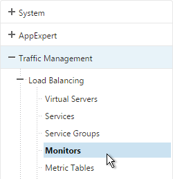
  1. In the NetScaler Configuration Utility, expand Traffic Management, expand Load Balancing, and click Monitors.
  2. On the right, click Add.
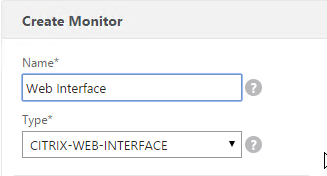
  3. Name the monitor ldaps-Corp or similar. The ldaps monitor logs into Active Directory, performs an LDAP query, and looks for a successful response. The monitor configuration has domain specific information, so if you have multiple Active Directory domains, then you will need multiple ldaps monitors. Include the domain name in the monitor name.
  4. Change the Type to LDAP.
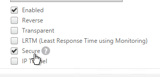
  5. Scroll down and check the box next to Secure.
  6. Scroll back up and switch to the Special Parameters tab.
  7. On the Special Parameters tab, use the Script Name drop-down list to select the nsldap.pl file.
  8. In the Base DN field, enter your domain name in LDAP format (e.g. dc=company,dc=com)
  9. In the Bind DN field, enter the UPN login (e.g. ctxsvc@company.com) of a service account in the domain that can browse all objects. Any normal Domain User should be sufficient. Just make sure the password doesn’t expire.
  10. In the Filter field, enter cn=builtin. This limits the search results.
  11. In the Password field, enter the password for the service account. Make sure there is no semicolon in the password or the script will be unable to parse the parameters.
  12. Click Create.

    add lb monitor LDAP-Corp LDAP -scriptName nsldap.pl -dispatcherIP 127.0.0.1 -dispatcherPort 3013 -password Passw0rd -secure YES -baseDN "dc=corp,dc=local" -bindDN "corp\\ctxsvc" -filter cn=builtin
  13. If you have multiple domains, then create additional monitors: one for each domain.

Servers

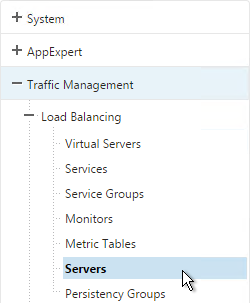
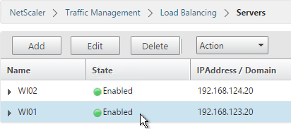
  1. On the left, expand Traffic Management, expand Load Balancing, and click Servers.
  2. On the right, click Add.
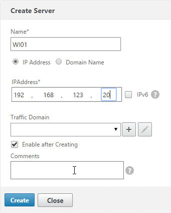
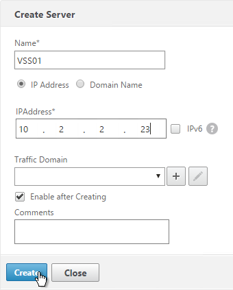
  3. Enter a descriptive server name, usually it matches the actual server name.
  4. Enter the IP address of the server.
  5. Enter comments to describe the server. Click Create.

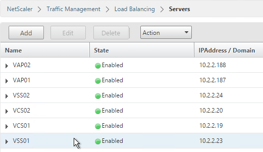
    add server AD01 10.2.2.11
    add server AD01 10.2.2.12
  6. Continue adding Domain Controllers.

Service Groups

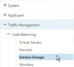
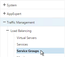
  1. On the left, expand Traffic Management, expand Load Balancing, and click Service Groups.
  2. On the right, click Add
    .
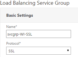
  3. You will create one Service Group per datacenter. Enter a name reflecting the name of the data center. Also, you will create a set of service groups per Active Directory domain so include the domain name.
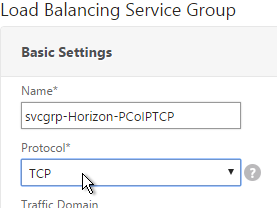
  4. Change the Protocol to SSL_TCP. Scroll down, and click Continue.
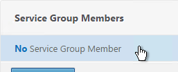
  5. On the left, in the Service Group Members section, click where it says No Service Group Member.
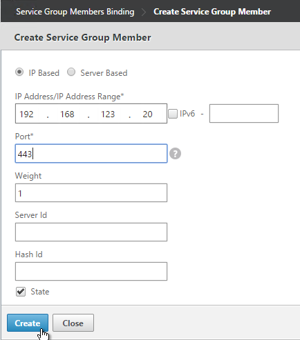
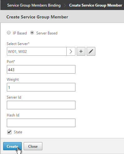
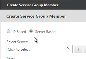
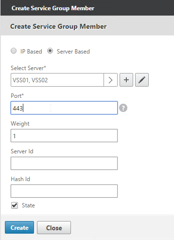
  6. If you did not create server objects then enter the IP address of a Domain Controller in this datacenter. If you previously created a server object then change the selection to Server Based, and select the server object. In the Port field, enter 636 (LDAPS).
  7. Note: Any Domain Controller you add to this list must have an SSL certificate installed. The easiest way to install SSL certificates on the Domain Controllers is with Active Directory Certificate Services since it installs the certificates automatically.

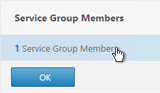
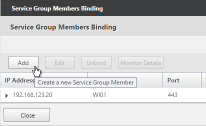
  8. To add more members, click where it says 1 Service Group Member, and then click Add. Click Close when done.

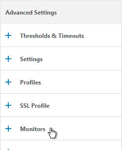
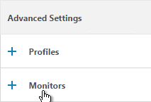
  9. On the right, in the Advanced Settings column, click Monitors.
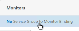
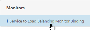
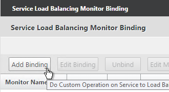
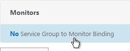
  10. On the left, in the Monitors section, click where it says No Service Group to Monitor Binding.
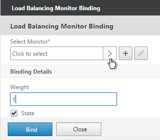
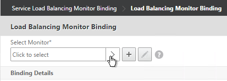
  11. Click the arrow next to Click to select.
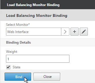
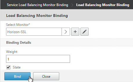
  12. Select your new LDAPS monitor and click Select.
  13. Click Bind.
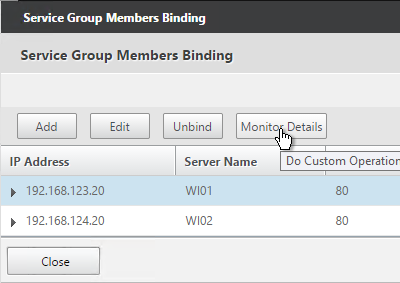
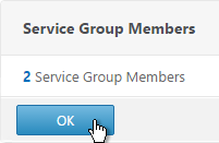
  14. To verify the member is up, click in the Service Group Members section.
  15. Highlight a member, and click Monitor Details.
  16. It should say Probe successful. Click OK.
  17. If the monitor doesn’t work, use ldp.exe to verify the Domain Controller certificate.
  18. Click Done to finish creating the Service Group.

    add serviceGroup svcgrp-LDAP-Corp SSL_TCP
    bind serviceGroup svcgrp-LDAP-Corp AD01 636
    bind serviceGroup svcgrp-LDAP-Corp AD02 636
    bind serviceGroup svcgrp-LDAP-Corp -monitorName LDAP-Corp
  19. The Service Group is displayed as UP. If not, click the refresh icon on the top right.
  20. Add additional service groups for Domain Controllers in each data center.

Virtual Server

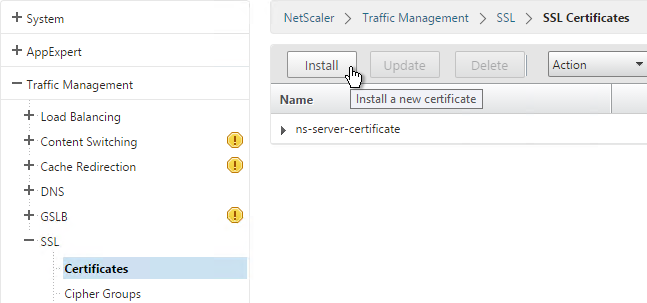
  1. Create or import a certificate that matches the FQDN that resolves to the new Load Balancing VIP for LDAPS.
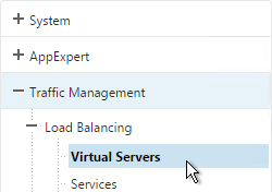
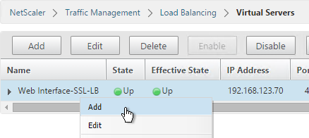
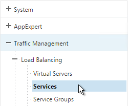
  2. On the left, expand Traffic Management, expand Load Balancing, and click Virtual Servers.

  3. On the right, click Add.
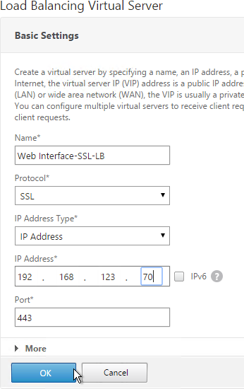
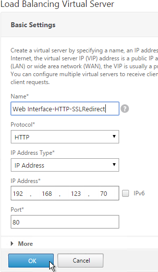
  4. Name it lbvip-LDAPS-Corp-HQ or similar. You will create one Virtual Server per datacenter so include the datacenter name. Also, each domain has a separate set of Virtual Servers so include the domain name.
  5. Change the Protocol drop-down to SSL_TCP.
  6. Enter a Virtual IP. This VIP cannot conflict with any other IP/Port already being used. You can use an existing VIP that is not already listening on TCP 636.
  7. Enter 636 as the Port. Click OK.
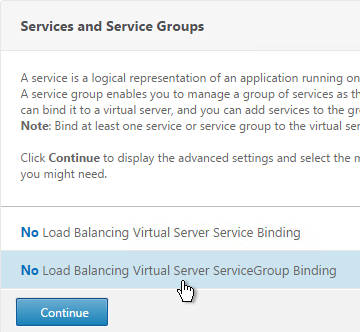
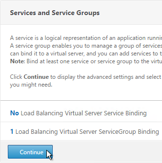
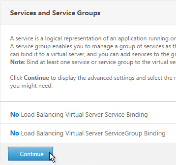
  8. On the left, in the Service Group section, click where it says No Load Balancing Virtual Server ServiceGroup Binding.
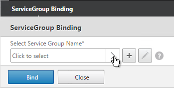
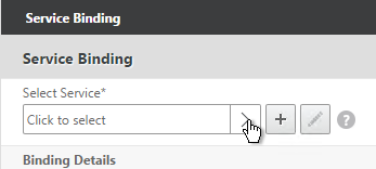
  9. Click the arrow next to Click to select.
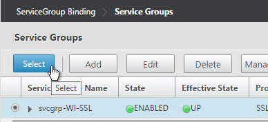
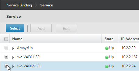
  10. Select the previously created Service Group, and click Select.
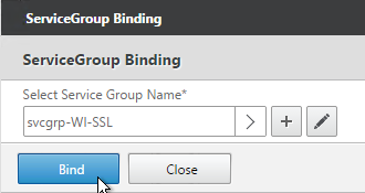
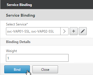
  11. Click Bind.
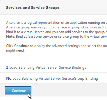
  12. Click Continue.
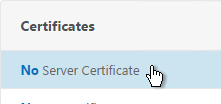
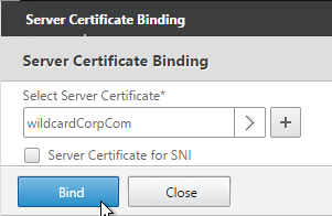
  13. On the left, in the Certificates section, click where it says No Server Certificate.
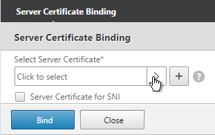
  14. Click the arrow next to Click to select.
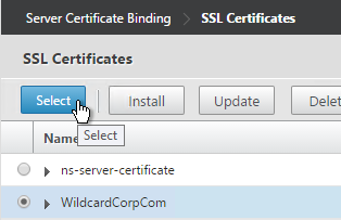
  15. Select a certificate that matches the FQDN that will resolve to this VIP. Click Select.
  16. Click Bind.
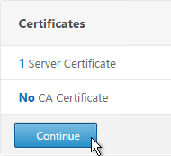
  17. Click Continue.

    add lb vserver lbvip-LDAP-Corp SSL_TCP 10.2.2.210 636 -persistenceType NONE -cltTimeout 9000
    
    bind lb vserver lbvip-LDAP-Corp svcgrp-LDAP-Corp
  18. If you haven’t enabled the Default SSL Profile, then perform other normal SSL configuration including: disable SSLv3, and bind a Modern Cipher Group.
    bind ssl vserver MyvServer -certkeyName MyCert
    
    set ssl vserver MyvServer -ssl3 DISABLED -tls11 ENABLED -tls12 ENABLED
    
    unbind ssl vserver MyvServer -cipherName ALL
    
    bind ssl vserver MyvServer -cipherName Modern
    
    bind ssl vserver MyvServer -eccCurveName ALL
  19. Click Done to finish creating the Virtual Server.
  20. The new Virtual Server should show as Up.
  21. Create additional Virtual Servers for each datacenter. These additional Virtual Servers do not need a VIP so change the IP Address Type to Non Addressable. Only the first Virtual Server will be accessible.

    add lb vserver lbvip-LDAP-Corp-Backup SSL_TCP 0.0.0.0 0
  22. Notice that the additional datacenter Virtual Servers show up with an IP Address of 0.0.0.0 and port of 0.
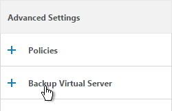
  23. After you are done creating a Virtual Server for each datacenter, right-click the primary datacenter’s Virtual Server, and click Edit.
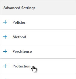
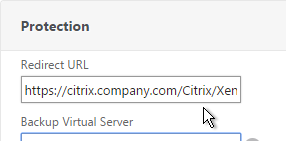
  24. On the right, in the Advanced Settings column, click Protection.
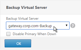
  25. On the left, in the Protection section, change the Backup Virtual Server to one of the other datacenter Virtual Servers. If all of the services in this datacenter are DOWN, the backup Virtual Server will be used instead. You can cascade multiple Virtual Servers using this method. Click OK and Done.

    set lb vserver lbvip-LDAP-Corp -backupVServer lbvip-LDAP-Corp-Backup

Clear Text LDAP

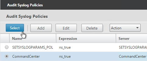
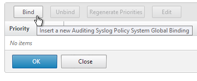
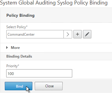
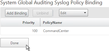
Citrix Command Center does not support Secure LDAP so you will need to do the following:

  1. Create a regular LDAP monitor that does not have the secure box checked.
  2. Create Service Groups of Protocol TCP and Port 389.
  3. Create a Load Balancing Virtual Server of Protocol TCP on port 389. Bind the Service Groups to it.

Next Steps

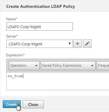
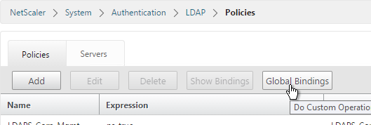
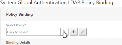
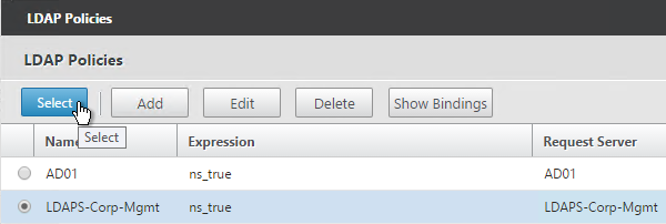
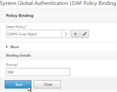
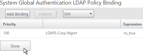
You may now use this Virtual IP in your LDAP authentication policies for NetScaler Gateway or NetScaler management login.

NetScaler SDX 10.5

Last Modified: Nov 6, 2020 @ 7:09 am

Navigation

SDX IP Configuration

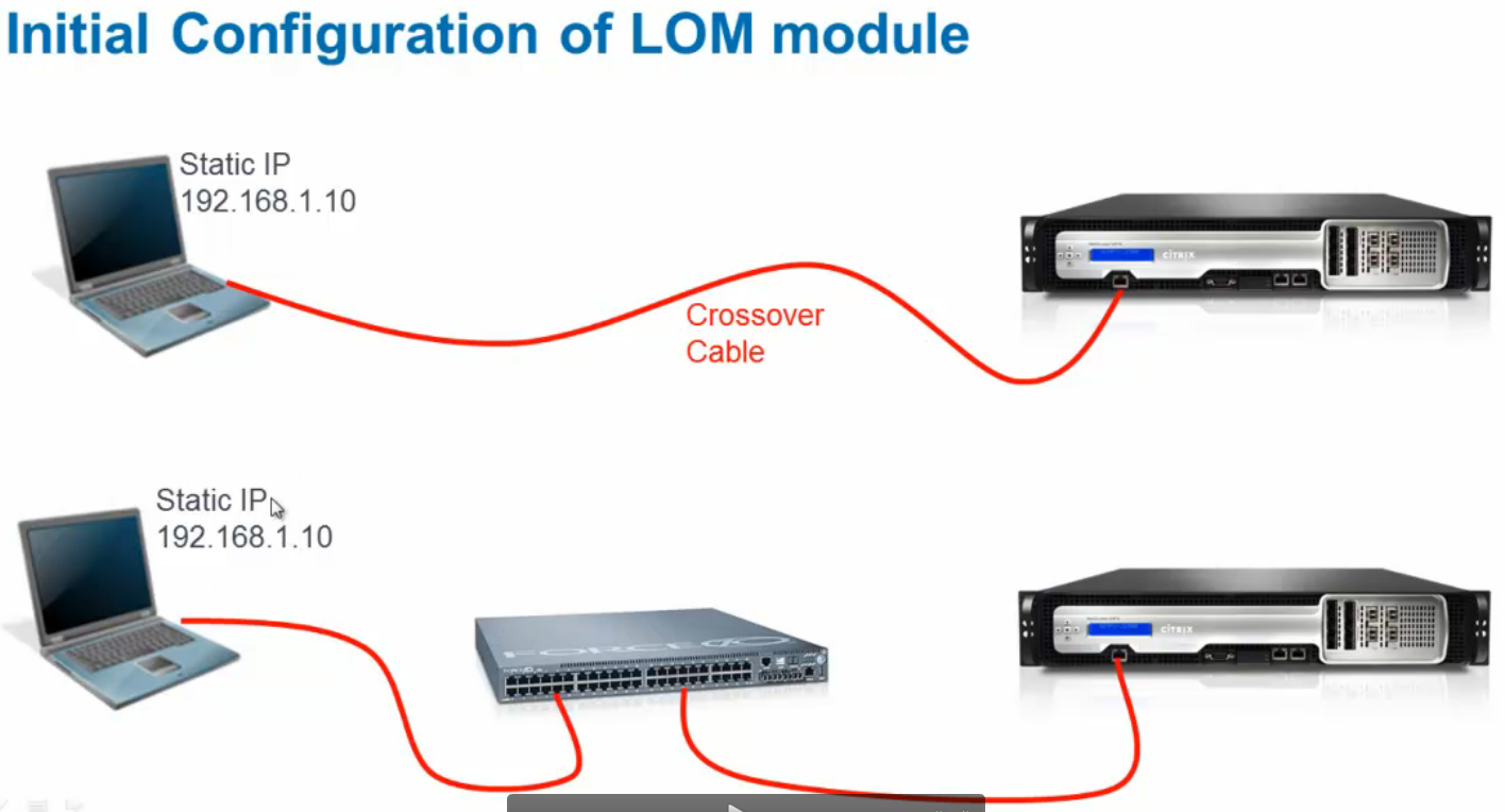
Default IP for Management Service VM is 192.168.100.1/16 bound to interface 0/1. Use laptop with crossover cable to reconfigure. Point browser to http://192.168.100.1. Default login is nsroot/nsroot.

Default IP for XenServer is 192.168.100.2/16. Default login is root/nsroot. Use the Management Service virtual machine to configure. XenServer and Management Service IPs must be on the same subnet.

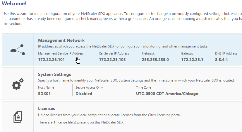
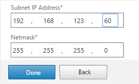
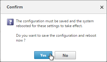
  1. When you first login to the SDX Service virtual machine, the Setup Wizard appears. In the Network Configuration page, configure the IP addresses. Management Service IP Address and XenServer IP Address must be different but on the same subnet. Scroll down.
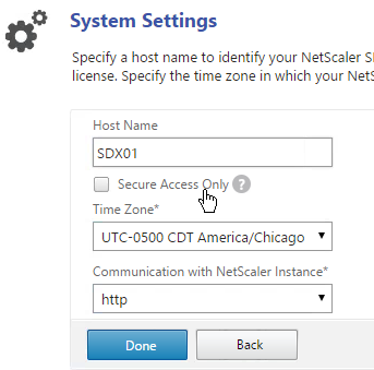
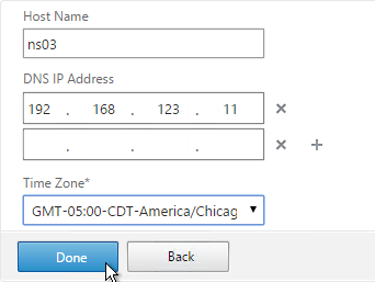
  2. In the System Settings page, select the time zone.
  3. Check the box next to Change Password, enter the new password. Click Continue.
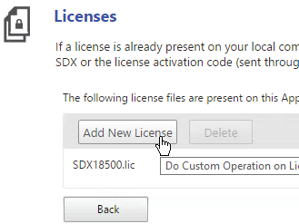
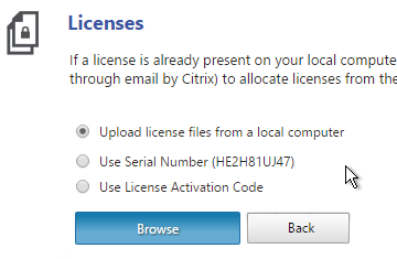
  4. In the Manage Licenses section, allocate licenses normally. Click Continue when done.
  5. Then click Done.

To modify the network configuration of the SDX appliance:

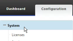
  1. Switch to the Configuration tab.
  2. In the navigation pane, click System.
  3. In the System pane, under Setup Appliance, click Network Configuration.
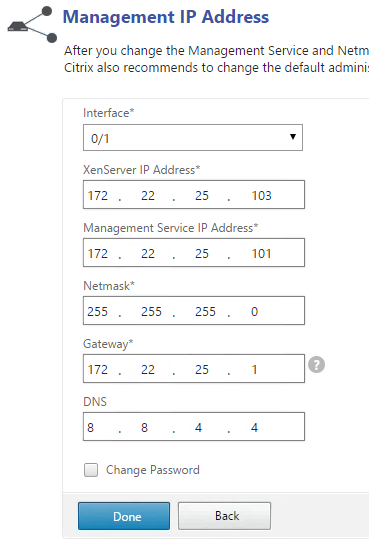
  4. In the Modify Network Configuration dialog box, specify values for the following parameters:
    • Interface*—The interface through which clients connect to the Management Service. Possible values: 0/1, 0/2. Default: 0/1.
    • XenServer IP Address*—The IP address of the XenServer.
    • Management Service IP Address*—The IP address of the Management Service.
    • Netmask*—The netmask for the subnet in which the SDX appliance is located.
    • Gateway*—The default gateway for the network.
    • DNS Server—The IP address of the DNS server.
  5. Click OK.


Another way to login to the Management Service virtual machine is through the serial port. This is actually the XenServer Dom0 console. Once logged in to XenServer, run ssh 169.254.0.10 to access the Management Service virtual machine. Then follow instructions at http://support.citrix.com/article/CTX130496 to change the IP.

The console of the Management Service virtual machine can be reached by running the following command in the XenServer Dom0 shell (SSH or console):

xe vm-list params=name-label,dom-id name-label=”Management Service VM“

Then run /usr/lib/xen/bin/xenconsole <dom-id>.

Service VM Firmware – Upgrade

  1. If the webpage says NetScaler SDX on top then you are connected to the Service VM.
  2. Switch to the Configuration tab.
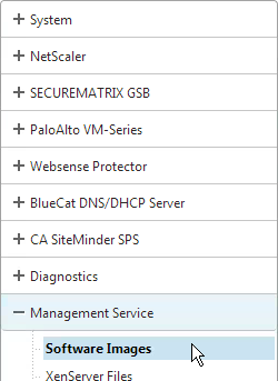
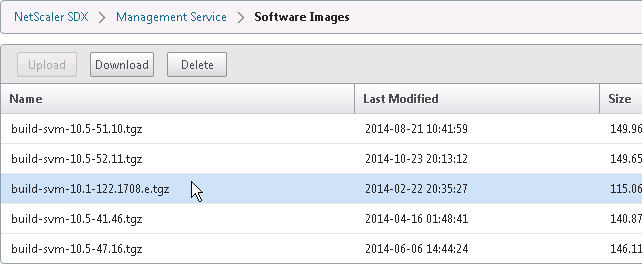
  3. In the navigation pane, expand Management Service, and then click Software Images.
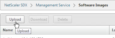
  4. In the right pane, click Upload.
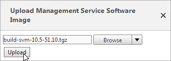
  5. In the Upload Management Service Software Image dialog box, click Browse, navigate to the folder that contains the build-svm file, and then double-click the build file.
  6. Click Upload.

To upgrade the Management Service:

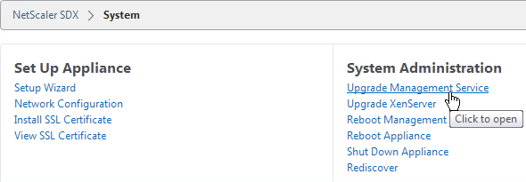
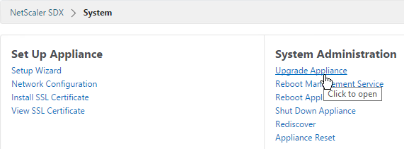
  1. In the navigation pane, click System.
  2. In the System pane, under System Administration, click Upgrade Management Service.
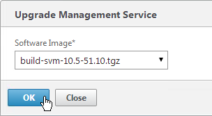
  3. In the Upgrade Management Service dialog box, in Build File, select the file of the build to which you want to upgrade the Management Service.
  4. If you see a Documentation File field, ignore it.
  5. Click OK.
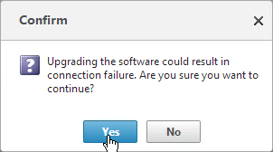
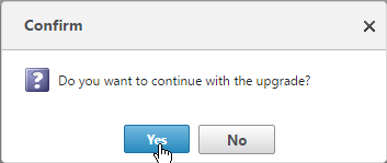
  6. Click Yes if asked to continue.
  7. If desired, go back to the Software Images node and delete older firmware files.

XenServer – Upgrade

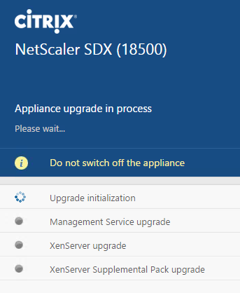
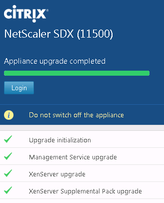
SDX Service VM 10.1 or newer requires XenServer 6.1 to be installed on the SDX appliance. Make sure you use the XenServer 6.1 media that is specific to SDX. It should be named XenServer-6.1.0-install-sdx.iso. Installing XenServer will cause the physical appliance (and all VPX instances) to reboot.

  1. Switch to the Configuration tab.
  2. In the navigation pane, expand Management Service, and then click XenServer Files.
  3. In the right pane, in the ISO Images tab, click Upload.
  4. In the Upload XenServer ISO Image File dialog box, click Browse, navigate to the folder that contains the build file, and then double-click the build file.
  5. Click Upload.


To upgrade the XenServer software:

  1. In the Configuration tab navigation pane, click System.
  2. In the details pane, click Upgrade XenServer.
  3. In the Upgrade XenServer section, select the Image file from the list. Then click OK.
  4. Click Yes to confirm that a connection failure will occur.

XenServer Supplemental Pack

A full reboot of the physical appliance will occur.

  1. Download the XenServer 6.1 Supplemental Pack from the same download page containing the SDX Service VM firmware. It’s in the Additional Components section.
  2. On the Configuration page, on the left, expand Management Service and click XenServer Files.
  3. On the right, switch to the Supplemental Packs tab and click Upload.
  4. Browse to the Supplemental Pack and click Upload.
  5. Select the Supplemental Pack and click Install.

  6. Click Yes when prompted to reboot the appliance.


XenServer Hotfixes

A full reboot of the physical appliance will occur.

  1. On the left, expand Management Service and click XenServer Files.
  2. On the right, switch to the Hotfixes tab and click Upload.
  3. Upload XenServer 6.1 Hotfix 44.
  4. Also upload XenServer 6.1 Hotfix 45.
  5. Also upload XenServer 6.1 Hotfix 48.
  6. Highlight one of the hotfixes and click Apply.
  7. Click Yes when asked to apply.
  8. Apply the next hotfix.
  9. Click Yes when asked to apply. Repeat for the remaining hotfixes.
  10. On the left, click the System node.
  11. On the right, in the right column, click Reboot Appliance.
  12. Click Yes when asked to reboot.


Service VM Hostname

  1. On the Configuration tab, click System.
  2. In the right pane, click Change Hostname in the System Settings section.
  3. Enter a new hostname and click OK.

Service VM Time Zone and NTP

  1. Go to Configuration tab and click System on the left.
  2. On the right, under System Settings click Change Time Zone.
  3. Select the time zone. For Central time, look for UTC-0500 and Chicago.


To configure an NTP server:

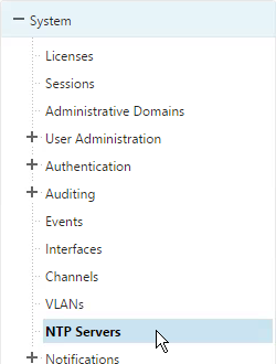
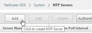
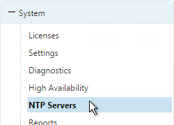
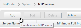
  1. On the Configuration tab, in the navigation pane, expand System, and then click NTP Servers.
  2. To add a new NTP server, in the right pane, click Add.
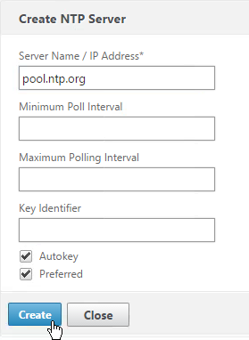
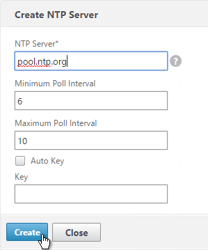
  3. In the Create NTP Server dialog box, set the following parameters:
    • Server Name/IP Address*—The domain name of the NTP server or the IP address of the NTP server. The name or IP address cannot be changed for an existing NTP server.
    • Preferred—Synchronize with this server first. Applicable if more than one server is configured.
  4. Click Add.
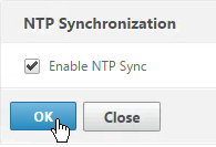
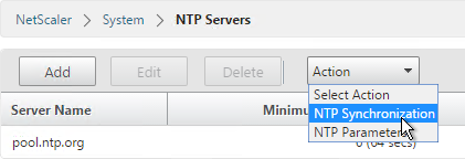
  5. In the right pane click NTP Synchronization.
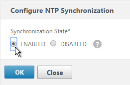
  6. In theNTP Synchronization dialog box, select Enable NTP Sync. Click OK.

Licensing

To upload a license file to the SDX appliance:

  1. Login to Citrix.com and go to Account.
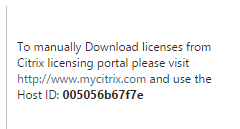
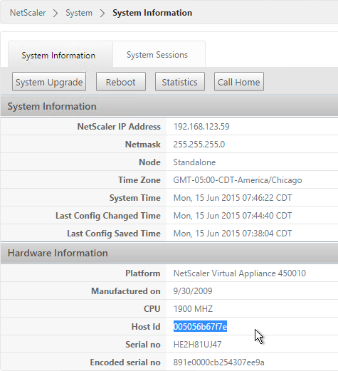
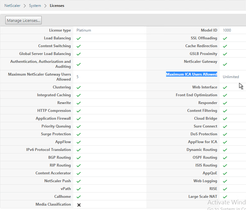
  2. Click Allocate Licenses, find a NetScaler SDX license, and allocate it. There is no need to specify a hostname. You can use the same license file on multiple SDX appliances.
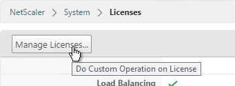
  3. On the Configuration tab, in the navigation pane, expand System, and then click Licenses.
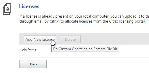
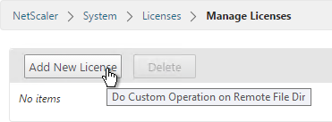
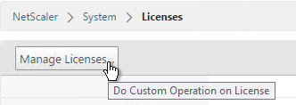
  4. In the right pane, click Manage Licenses.
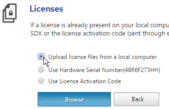
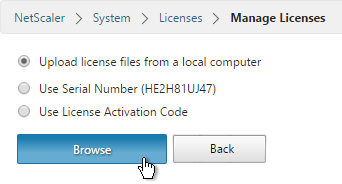
  5. In the Manage Licenses page, select Upload License Files and click Upload.
  6. In the Upload License File dialog box, do the following:
    1. Click Browse.
    2. Navigate to the folder that contains the license file you want to upload, and then double-click the license file.
    3. Click Upload.
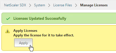
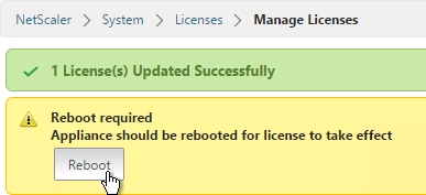
  7. In the License Files pane, click Apply Licenses.
  8. In the Confirm message box, click Yes.

Service VM Alerting

Syslog:

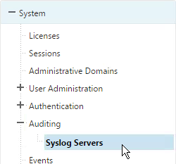
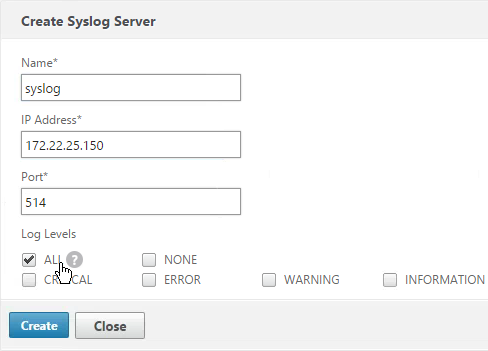
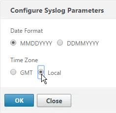
  1. On the Configuration tab, expand System > Notifications and click Syslog Servers.
  2. In the right pane click the Add button.
  3. Enter a name for the server.
  4. Enter the IP address of the Syslog server.
  5. Select log levels and click Add.


Mail Notification

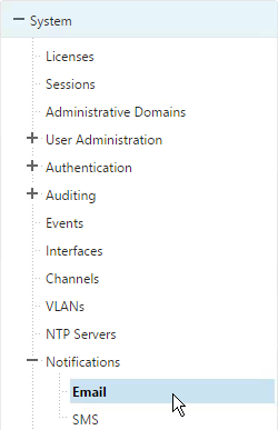
  1. On the Configuration tab, expand System > Notifications and click Email.
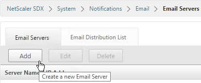
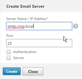
  2. In the right pane, on the SMTP Server tab, click Add.
  3. Enter the DNS name of the mail server and click Create.
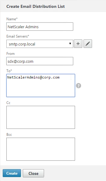
  4. In the right pane, switch to the Email Distribution List tab and click Add.
  5. Enter a name for the mail profile.
  6. Enter the destination email address and click Create.
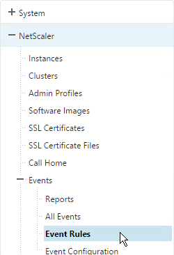
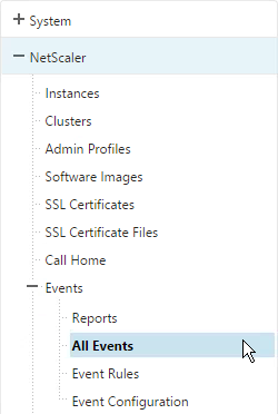
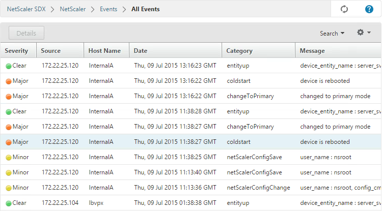
  7. The instances will send SNMP traps to the Service VM. To get alerted for these traps, in the Configuration page, in the navigation pane, expand NetScaler, expand Events, and click Event Rules.
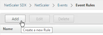
  8. On the right, click Add.
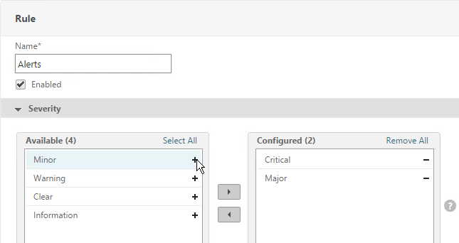
  9. Give the rule a name.
  10. Select the Major and Critical severities and move them to the right. Scroll down.
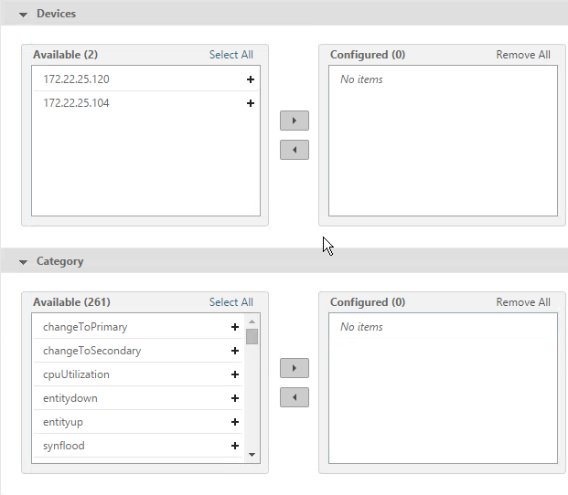
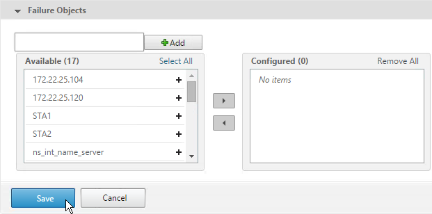
  11. For the other sections, if you don’t configure anything then you will receive alerts for all of the devices, categories, and failure objects. If you configure any of them then only the configured entities will be alerted. Scroll down.
  12. Click Save.
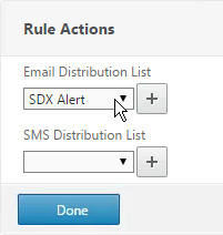
  13. Select an Email Distribution List and click Done.

Service VM nsroot Password and AAA

To change the password of the default user account:

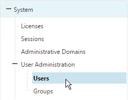
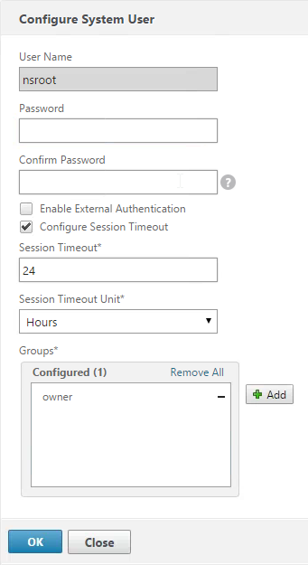
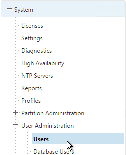
  1. On the Configuration tab, in the navigation pane, expand System, and then click Users.
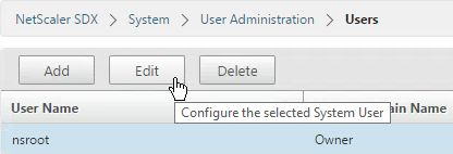
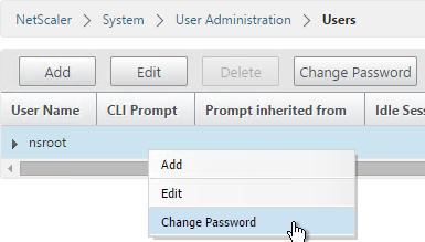
  2. In the Users pane, click the default user account, and then click Edit.
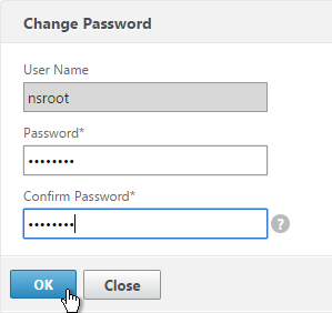
  3. In the Configure System User dialog box, in Password and Confirm Password, enter the password of your choice. Click OK.

To create a user account:

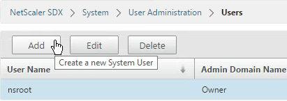
  1. In the navigation pane, expand System, and then click Users. The Users pane displays a list of existing user accounts, with their permissions.
  2. To create a user account, click Add.
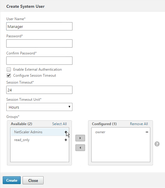
  3. In the Create System User or Modify System User dialog box, set the following parameters:
    • Name*—The user name of the account. The following characters are allowed in the name: letters a through z and A through Z, numbers 0 through 9, period (.), space, and underscore (_). Maximum length: 128. You cannot change the name.
    • Password*—The password for logging on to the appliance.
    • Confirm Password*—The password.
    • Session Timeout
    • Groups —The user’s privileges on the appliance. Possible values:
      • owner—The user can perform all administration tasks related to the Management Service.
      • readonly—The user can only monitor the system and change the password of the account.
  4. Click Create. The user that you created is listed in the Users pane.


AAA Authentication:

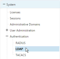
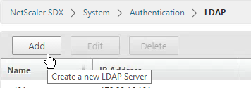
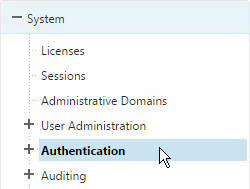
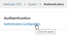
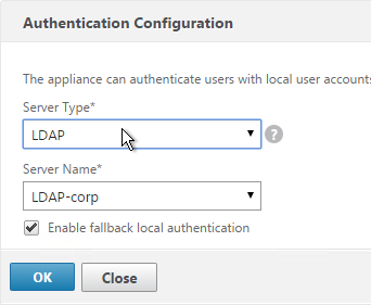
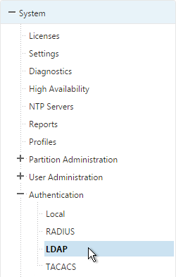
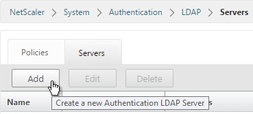
  1. If you would like to enable LDAP authentication for the Service VM, do that under Configuration > System > Authentication > LDAP.
  2. In the right pane, click Add.
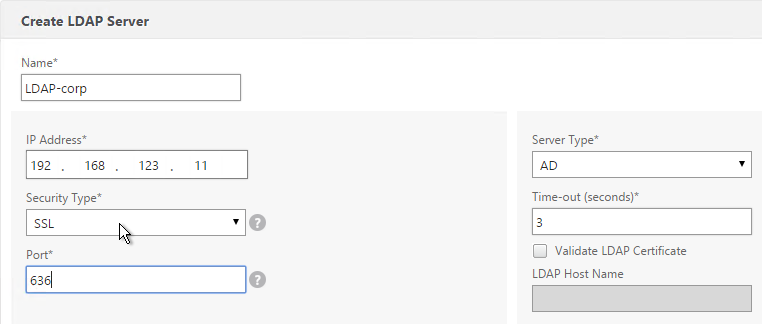
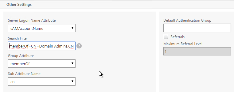
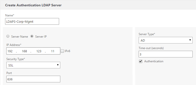
  3. Enter the LDAP settings. Change the port to 636 if using Secure LDAP (recommended). Enter the bind account. Scroll down.
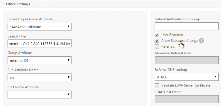
  4. Change the Security Type to SSL. Check the box next to Enable Change Password. Click Create.
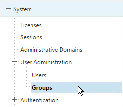
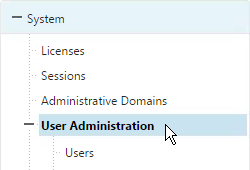
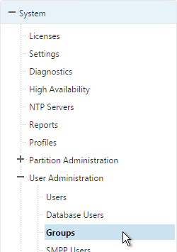
  5. Expand System, expand User Administration and click Groups.
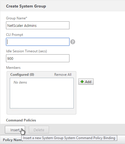
  6. Click Add.
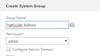
  7. Enter the case sensitive name of the Active Directory group.
  8. Select the admin permission.
  9. Configure the Session Timeout. Click Create.

SSL Certificate and Encryption

Replace SDX Service VM Certificate:

Before enabling secure access to the Service VM web console, you probably want to replace the Service VM certificate.

  1. PEM format: The certificate must be in PEM format. The Service VM does not provide any mechanism for converting a PFX file to PEM. You can convert from PFX to PEM by using the Import PKCS#12 task in a NetScaler instance.
  2. On the Configuration tab, expand Management Service and click SSL Certificate Files.
  3. On the right, click Upload.
  4. Browse to the certificate PEM file and click Upload.
  5. On the right, switch to the SSL Keys tab and click Upload.
  6. Browse to the PEM key file. This could be the same file containing the certificate or a separate file. Click Upload.
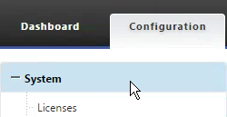
  7. On the left, click System.
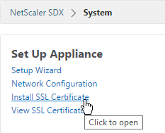
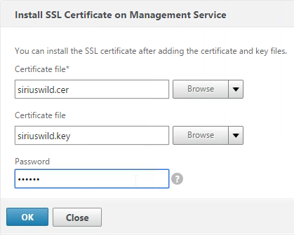
  8. On the right, click Install SSL Certificate.
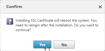
  9. Select the uploaded certificate and key files. If the key file is encrypted, enter the password. Then click OK. The Service VM will restart so there will be an interruption.
  10. After the Service VM restarts, connect to it using HTTPS. You can’t make this change if you are connected using HTTP.
  11. On the Configuration tab, click System.
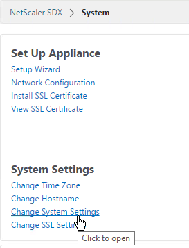
  12. On the right, click Change System Settings.
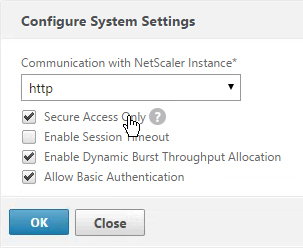
  13. Check the box next to Secure Access Only and click OK. This forces you to use HTTPS to connect to the Service VM.


SSL Encrypt Management Service to NetScaler Communication:

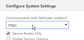
From http://support.citrix.com/article/CTX134973: Communication from the Service Virtual Machine to the NetScaler VPX instances is HTTP by default. If you want to configure HTTPS access for the NetScaler VPX instances, then you have to secure the network traffic between the Service Virtual Machine and NetScaler VPX instances. If you do not secure the network traffic from the Service Virtual Machine configuration, then the NetScaler VPX Instance State appears as Out of Service and the Status shows Inventory from instance failed.

  1. Log on to the Service Virtual Machine Graphical User Interface (GUI) management.
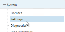
  2. On the Configuration tab, click System.
  3. On the right, click Change System Settings.
  4. Change Communication with NetScaler Instance to https, as shown in the following screen shot:
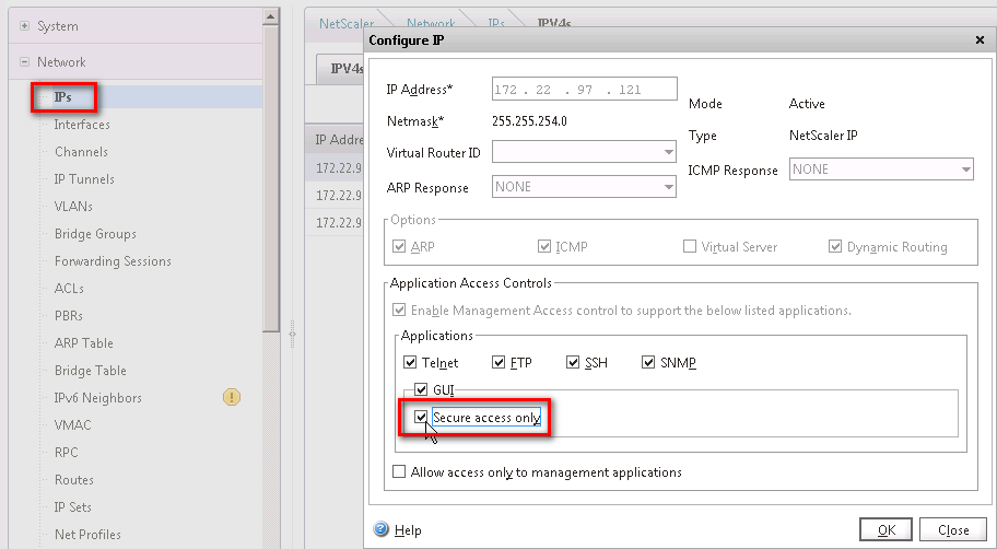
  5. Run the following command on the NetScaler VPX instance, to change the Management Access (-gui) to SECUREONLY:

set ns ip ipaddress -netmask netmask -arp ENABLED -icmp ENABLED -vServer DISABLED -telnet ENABLED -ftp ENABLED -gui SECUREONLY -ssh ENABLED -snmp ENABLED - mgmtAccess ENABLED -restrictAccess DISABLED -dynamicRouting ENABLED -ospf DISABLED -bgp DISABLED -rip DISABLED -hostRoute DISABLED -vrID 0

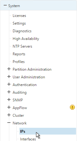
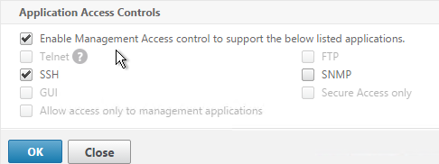
Or in the NetScaler instance management GUI go to Network > IPs, open the NSIP and then check the box next to Secure access only.

XenServer LACP Channels

To use LACP, configure Channels in the Service VM, which creates them in XenServer. Then when provisioning an instance, connect it to the Channel. If you are instead using static port channels, you can configure them inside a VPX instance.

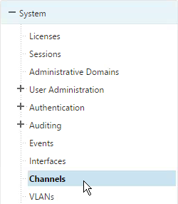
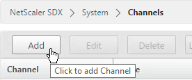
  1. In the Service VM, on the Configuration tab, expand System and click Channels.
  2. On the right, click Add.
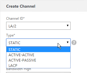
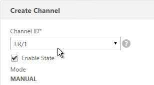
  3. Select a Channel ID.
  4. For Type, select LACP or STATIC. The other two options are for switch independent load balancing.
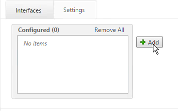
  5. In the Interfaces tab, click Add.
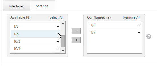
  6. Move the Channel Member interfaces to the right by clicking the plus icon.
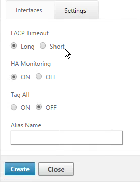
  7. On the Settings tab, you can select Long or Short, depending on switch configuration. Long is the default.
  8. Click Create when done.
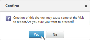
  9. Click Yes when asked to proceed.
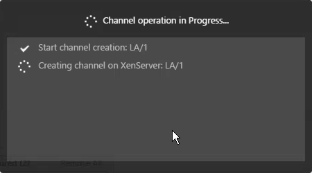
  10. The channel will then be created on XenServer.

VPX Instances – Provision

To create an admin profile:

Admin profiles specify the user credentials that are used by the Management Service when provisioning the NetScaler instances, and later when communicating with the instances to retrieve configuration data. The user credentials specified in an admin profile are also used by the client when logging on to the NetScaler instances through the CLI or the configuration utility.

The default admin profile for an instance specifies a user name of nsroot, and the password is also nsroot. This profile cannot be modified or deleted. However, you should override the default profile by creating a user-defined admin profile and attaching it to the instance when you provision the instance. The Management Service administrator can delete a user-defined admin profile if it is not attached to any NetScaler instance.

Important: Do not change the password directly on the NetScaler VPX instance. If you do so, the instance becomes unreachable from the Management Service. To change a password, first create a new admin profile, and then modify the NetScaler instance, selecting this profile from the Admin Profile list.

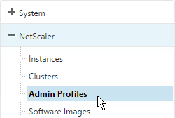
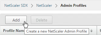
  1. On the Configuration tab, in the navigation pane, expand NetScaler Configuration, and then click Admin Profiles.
  2. In the Admin Profiles pane, click Add.
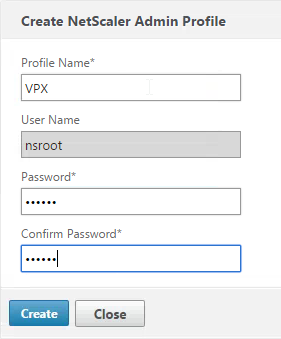
  3. In the Create Admin Profile dialog box, set the following parameters:
    • Profile Name*—Name of the admin profile. The default profile name is nsroot. You can create user-defined profile names.
    • User Name—User name used to log on to the NetScaler instances. The user name of the default profile is nsroot and cannot be changed.
    • Password*—The password used to log on to the NetScaler instance. Maximum length: 31 characters.
    • Confirm Password*—The password used to log on to the NetScaler instance.
  4. Click Create. The admin profile you created appears in the Admin Profiles pane.


To upload a NetScaler VPX .xva file:

You must upload a NetScaler VPX .xva file to the SDX appliance before provisioning the NetScaler VPX instances.

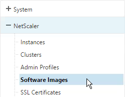
  1. On the Configuration tab, in the navigation pane, expand NetScaler Configuration, and then click Software Images.
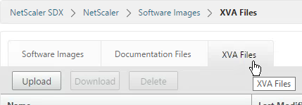
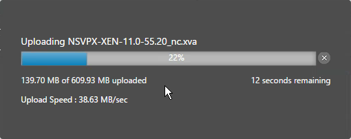
  2. On the right, switch to the XVA Files tab and then click Upload.
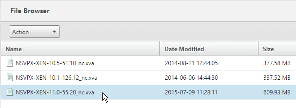
  3. In the Upload NetScaler Instance XVA dialog box, click Browse and select the XVA image file that you want to upload. Click Upload. The XVA image file appears in the NetScaler XVA Files pane after it is uploaded.


To provision a NetScaler instance:

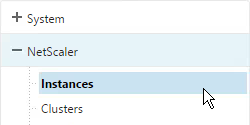
  1. On the Configuration tab, in the navigation pane, expand NetScaler Configuration, and then click Instances.
  2. In the NetScaler Instances pane, click Add.
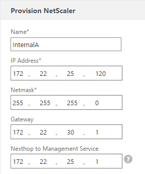
  3. In the Provision NetScaler Wizard follow the instructions in the wizard.
  4. Click Create. The NetScaler instance you provisioned appears in the NetScaler Instances pane.

The wizard will ask for the following info:

  • Name* – The host name assigned to the NetScaler instance.
  • IP Address* – The NetScaler IP (NSIP) address at which you access a NetScaler instance for management purposes. A NetScaler instance can have only one NSIP. You cannot remove an NSIP address.
  • Netmask* – The subnet mask associated with the NSIP address.
  • Gateway* – The default gateway that you must add on the NetScaler instance if you want access through SSH or the configuration utility from an administrative workstation or laptop that is on a different network.
  • XVA File* – The .xva image file that you need to provision. This file is required only when you add a NetScaler instance.
  • Feature License* – Specifies the license you have procured for the NetScaler. The license could be Standard, Enterprise, and Platinum.
  • Admin Profile* – The profile you want to attach to the NetScaler instance. This profile specifies the user credentials that are used by the Management Service to provision the NetScaler instance and later, to communicate with the instance to retrieve configuration data. The user credentials used in this profile are also used while logging on to the NetScaler instance by using the GUI or the CLI. It is recommended that you change the default password of the admin profile. This is done by creating a new profile with a user-defined password. For more information, see Configuring Admin Profiles.
  • Total Memory (MB)* – The total memory allocated to the NetScaler instance.
  • #SSL Cores* – Number of SSL cores assigned to the NetScaler instance. SSL cores cannot be shared. The instance is restarted if you modify this value.
  • Throughput (Mbps)* – The total throughput allocated to the NetScaler instance. The total used throughput should be less than or equal to the maximum throughput allocated in the SDX license. If the administrator has already allocated full throughput to multiple instances, no further throughput can be assigned to any new instance.
  • Packets per second* – The total number of packets received on the interface every second.
  • CPU – Assign a dedicated core or cores to the instance or the instance shares a core with other instance(s).
  • User Name* – The root user name for the NetScaler instance administrator. This user has superuser access, but does not have access to networking commands to configure VLANs and interfaces. (List of non-accessible commands will be listed here in later versions of this document)
  • Password* – The password for the root user.
  • Shell/Sftp/Scp Access* – The access allowed to the NetScaler instance administrator.
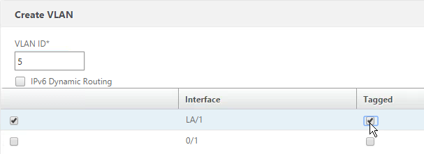
  • Interface Settings – This specifies the network interfaces assigned to a NetScaler instance. You can assign interfaces to an instance. For each interface, if you select Tagged, specify a VLAN ID.
    • Important:The interface ID numbers of interfaces that you add to an instance do not necessarily correspond to the physical interface numbering on the SDX appliance. For example, if the first interface that you associate with instance 1 is SDX interface 1/4, it appears as interface 1/1 when you log on to the instance and view the interface settings, because it is the first interface that you associated with instance 1.
    • If a non-zero VLAN ID is specified for a NetScaler instance interface, all the packets transmitted from the NetScaler instance through that interface will be tagged with the specified VLAN ID. If you want incoming packets meant for the NetScaler instance that you are configuring to be forwarded to the instance through a particular interface, you must tag that interface with the VLAN ID you want and ensure that the incoming packets specify the same VLAN ID.
    • For an interface to receive packets with several VLAN tags, you must specify a VLAN ID of 0 for the interface, and you must specify the required VLAN IDs for the NetScaler instance interface.
  • NSVLAN ID – An integer that uniquely identifies the NSVLAN. Minimum value: 2. Maximum value: 4095.
  • Tagged – Designate all interfaces associated with the NSVLAN as 802.1q tagged interfaces.
  • Interfaces – Bind the selected interfaces to the NSVLAN.


Here are screenshots from the wizard:

  1. On the Provision NetScaler page, enter a name for the instance.
  2. Enter the NSIP, mask, and Gateway.
  3. Select the XVA File with your desired firmware build.
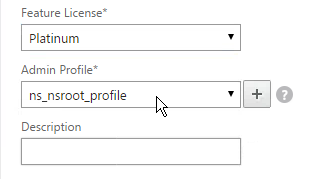
  4. Change the Feature License to Platinum.
  5. Select an Admin Profile created earlier.
  6. Enter a Description. Scroll down.
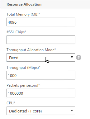
  7. In the Resource Allocation section, change the Total Memory to
  8. For SSL Chips, specify between 1 and 16.
  9. For Throughput, partition your licensed bandwidth. If you are licensed for 8 Gbps, make sure the total of all VPX instances does not exceed that number.
  10. For CPU, select one of the Dedicated options. Then scroll down.
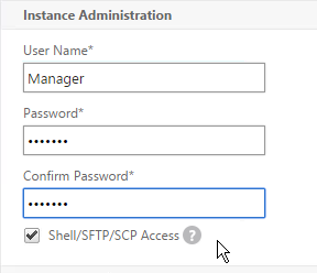
  11. In the Instance Administration section, enter a new local account that will be created on the VPX. This is in addition to the nsroot user. Note, not all functionality is available to this account. Scroll down.
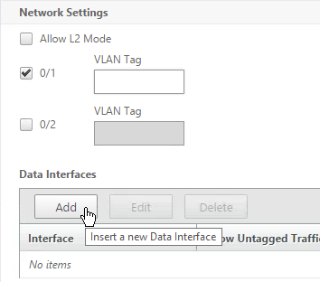
  12. In the Network Settings section, leave 0/1 selected and deselect 0/2.
  13. Click Add to connect the VPX to more interfaces.
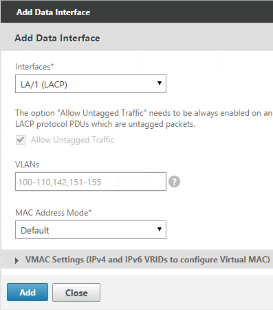
  14. If you have Port Channels, select one of the LA interfaces.
  15. Try not configure any VLAN settings here. If you do, XenServer filters the VLANs available to the VPX instance. Changing the VLAN filtering settings later probably requires a reboot. Click Add.
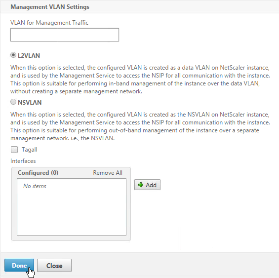
  16. In the Management VLAN Settings section, do not configure anything in this section unless you need to tag the NSIP VLAN. Click Done.
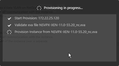
  17. After a couple minutes the instance will be created. Click Close.
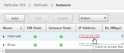
  18. In your Instances list, click the IP address to launch the VPX management console. Do the following at a minimum (instructions in the NetScaler System Configuration section):
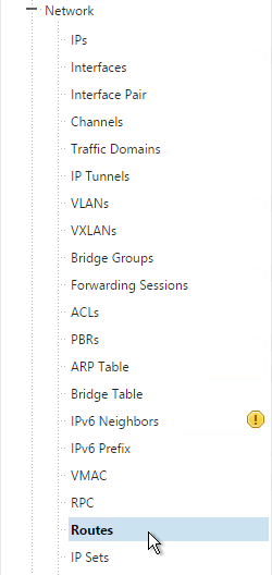
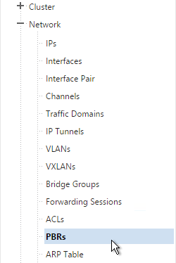
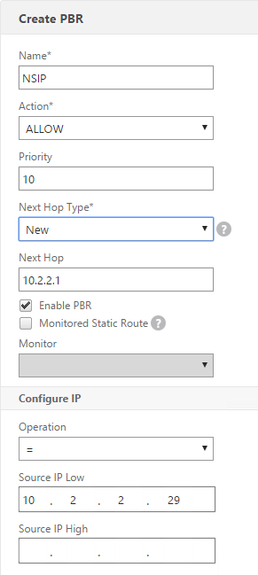
    1. Create Policy Based Route for the NSIP – System > Settings > Network > PBRs
    2. Add SNIPs for each VLAN – System > Network > IPs
    3. Add VLANs and bind to SNIPs – System > Network > VLANs
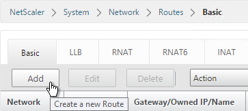
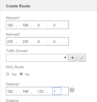
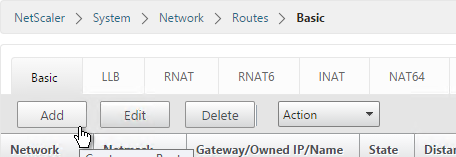
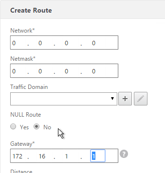
    4. Create Static Routes for internal networks – System > Network > Routes
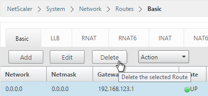
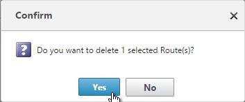
    5. Change default gateway – System > Network > Routes > 0.0.0.0
    6. Create another instance on a different SDX and High Availability pair them together – System > High Availability


Applying the Administration Configuration

At the time of provisioning a NetScaler VPX instance, the Management Service creates some policies, instance administration (admin) profile, and other configuration on the VPX instance. If the Management Service fails to apply the admin configuration at this time due to any reason (for example, the Management Service and the NetScaler VPX instance are on different subnetworks and the router is down or if the Management Service and NetScaler VPX instance are on the same subnet but traffic has to pass through an external switch and one of the required links is down), you can explicitly push the admin configuration from the Management Service to the NetScaler VPX instance at any time.

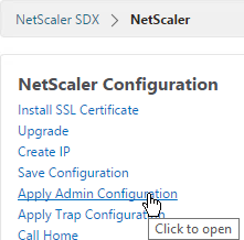
  1. On the Configuration tab, in the navigation pane, click NetScaler.
  2. In the NetScaler Configuration pane, click Apply Admin Configuration.
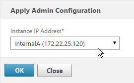
  3. In the Apply Admin Configuration dialog box, in Instance IP Address, select the IP address of the NetScaler VPX instance on which you want to apply the admin configuration.
  4. Click OK.

VPX Instances – Manage

You may login to the VPX instance and configure everything normally. SDX also offers the ability to manage IP address and SSL certificates from SDX rather than from inside the VPX instance. The SDX Management Service does not have the ability to create certificates so it’s probably best to do that from within the VPX instance.

To view the console of a NetScaler instance:

  1. Connect to the Service VM using https.
  2. Viewing the console might not work unless you replace the Service VM certificate.
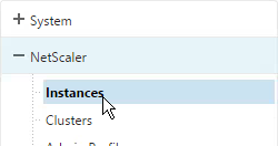
  3. In the Service VM, go to Configuration > NetScaler > Instances.
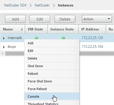
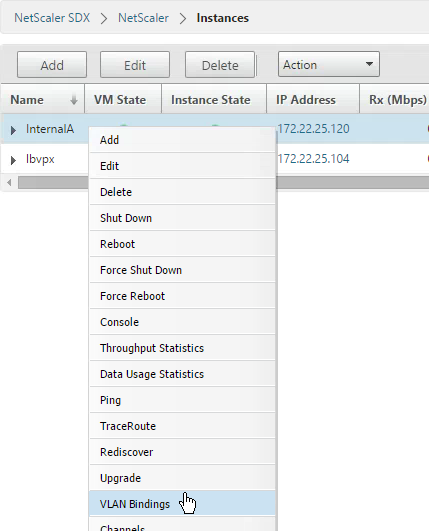
  4. On the right, right-click an instance and click Console.
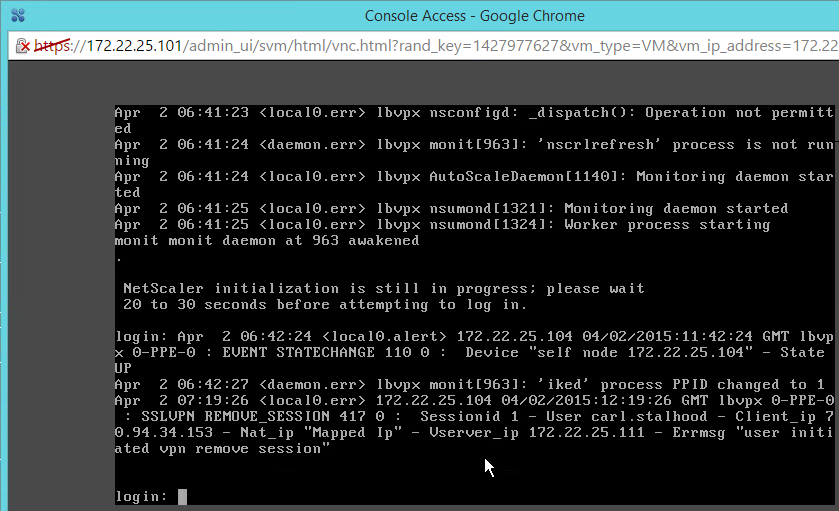
  5. The instance console then appears.
  6. Another option is to use the Lights Out Module and the xl console command as detailed at Citrix Blog Post SDX Remote Console Access of VIs.


To start, stop, delete, or restart a NetScaler instance:

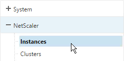
  1. On the Configuration tab, in the navigation pane, expand NetScaler and click Instances.
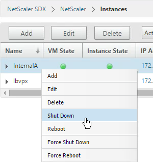
  2. In the Instances pane, right-click the NetScaler instance on which you want to perform the operation, and then click Start or Shut Down or Delete or Reboot.
  3. In the Confirm message box, click Yes.


Creating a Subnet IP Address on a NetScaler Instance:

You can create or delete a SNIP during runtime without restarting the NetScaler instance.

  1. On the Configuration tab, in the navigation pane, click NetScaler.
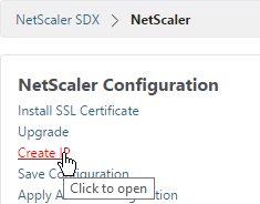
  2. In the NetScaler Configuration pane, click Create IP.
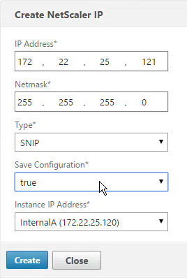
  3. In the Create NetScaler IP dialog box, specify values for the following parameters.
    • IP Address* – Specify the IP address assigned as the SNIP or the MIP address.
    • Netmask* – Specify the subnet mask associated with the SNIP or MIP address.
    • Type* – Specify the type of IP address. Possible values: SNIP.
    • Save Configuration* – Specify whether the configuration should be saved on the NetScaler. Default value is false.
    • Instance IP Address* – Specify the IP address of the NetScaler instance.
  4. Click Create.


To save the configuration on a NetScaler instance:

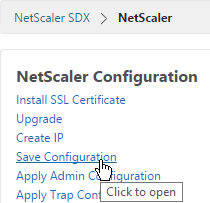
  1. On the Configuration tab, in the navigation pane, click NetScaler.
  2. In the NetScaler pane, click Save Configuration.
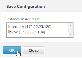
  3. In the Save Configuration dialog box, in Instance IP Address, select the IP addresses of the NetScaler instances whose configuration you want to save.
  4. Click OK.


Change NSIP of VPX Instance:

If you change NSIP inside of VPX instead of using the Modify Instance wizard in the Service VM, see article http://support.citrix.com/article/CTX139206 to adjust the XenServer settings.


Enable Call Home:

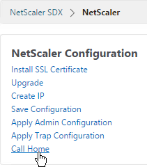
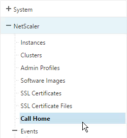
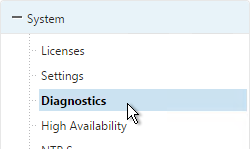
  1. On the Configuration tab, in the navigation pane, click the NetScaler node.
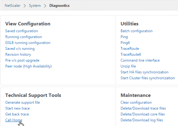
  2. On the right, click Call Home.
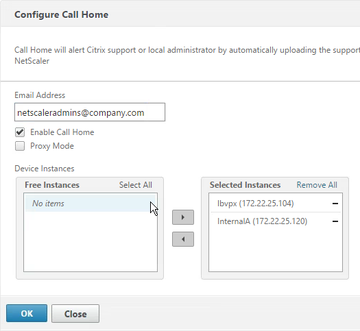
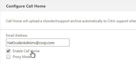
  3. Enter an email address to receive communications regarding NetScaler Call Home.
  4. Check the box next to Enable Call Home.
  5. Select the instances to enable Call Home and click OK.

VPX Instance – Firmware Upgrade

Upload NetScaler Firmware Build Files:

To upgrade a VPX instance from the Service VM, first upload the firmware build file.

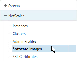
  1. In the Configuration tab, on the left, expand NetScaler and click Software Images.
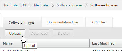
  2. On the right, in the Software Images tab click Upload.
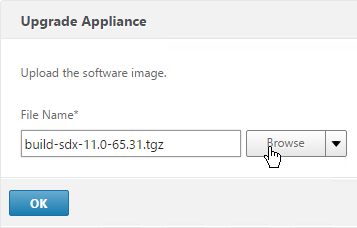
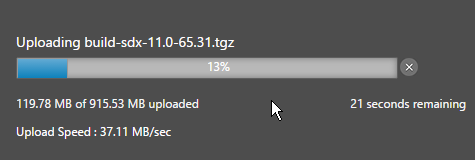
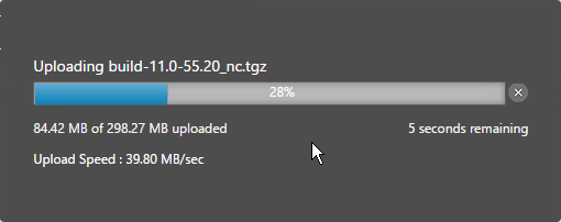
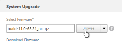
  3. Browse to the build…tgz file and click Upload.


Upgrading Multiple NetScaler VPX Instances:

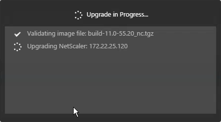
You can upgrade multiple instances at the same time.

  1. To prevent any loss of the configuration running on the instance that you want to upgrade, save the configuration on the instance before you upgrade the instance.
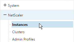
  2. On the Configuration tab, in the navigation pane, expand NetScaler and click Instances.
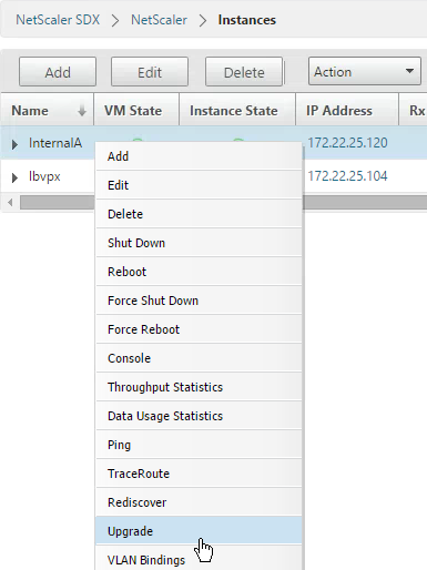
  3. Click an instance to highlight it. Open the Action menu and click Upgrade.
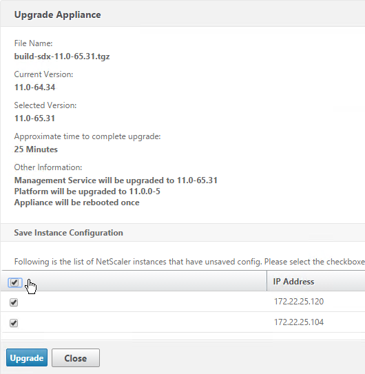
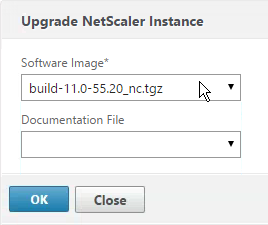
  4. In the Upgrade NetScaler dialog box, in Build File, select the NetScaler upgrade build file of the version you want to upgrade to. Ignore the Documentation File. Click OK.

Service VM Monitoring

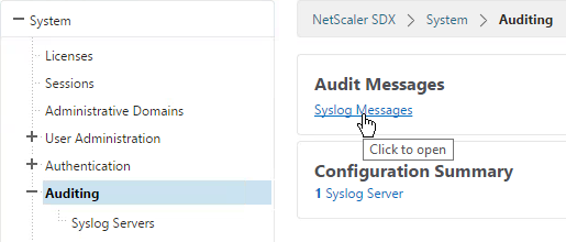
  1. To view the audit log, in the navigation pane, expand System, and then click Audit Logs.
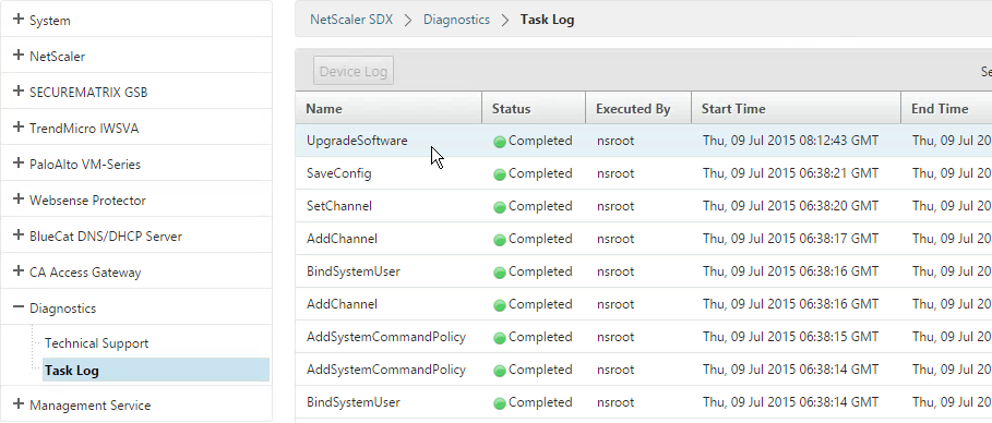
  2. To view the task log, in the navigation pane, expand Diagnostics, and then click Task Log.
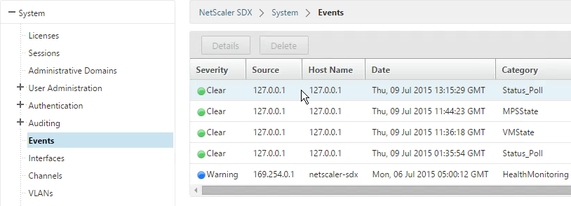
  3. To view events, on the Dashboard tab, in the System Health Events section on the bottom right, click Show All Events.

Service VM Backups

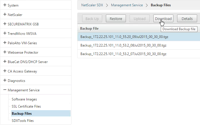
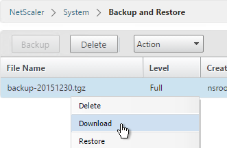
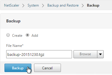
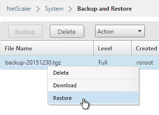
The SDX appliance automatically keeps three backups of the Service VM configuration that are taken daily at 12:30 am. Only configuration files and logs are backed up. This task does not backup the VPXs. You can go to Management Service > Backup Files to backup or restore the appliance’s configuration. And you can download the backup files.

Session Recording 7.13

Last Modified: Nov 7, 2020 @ 6:34 am

Navigation

This article applies to Session Recording 7.6 (including LTSR), 7.8, 7.11, 7.12, and 7.13. For 7.14 and newer, there’s a different article.

💡 = Recently Updated

Planning

George Kuruvilla – An Introduction To Session Recording (XA/XD 7.6 Feature Pack 1) – Installation, Configuration and User Experience

Citrix links:

XenApp/XenDesktop Platinum Edition licensing is required.

Remote Desktop Session Host VDAs added in Session Recording 7.6. Virtual desktops added in Session Recording 7.8.

There is no relation between Session Recording and XenApp/XenDesktop farms. You can have Agents from multiple XenApp/XenDesktop farms recording to a common Session Recording server. Or you can split a XenApp/XenDesktop farm so that different Agents point to different Session Recording servers. An Agent can only point to one Session Recording server (Load Balancing is not supported).

The Session Recording server will need a hard drive to store the recordings. Disk access is primarily writes.

Offloaded content (e.g. HDX Flash, Lync webcam, MMR) is not recorded.

Session Recording server needs a certificate. The certificate must be trusted by Agents and Players. Internal Certificate Authority recommended.

SQL:

  • Supported Versions = SQL 2008 R2 Service Pack 3 through SQL 2016.
  • The SQL database is very small.
  • The database name is CitrixSessionRecording. Can be changed in only 7.13 and newer.
  • Temporary sysadmin permissions are needed to create the database and sysadmin can be revoked after installation.
  • SQL Browser Service must be running.
  • As of Session Recording 7.13, SQL Server High Availability (AlwaysOn Availability Groups, Clustering, Mirroring) is supported. See Install Session Recording with database high availability at Citrix Docs. And see Citrix Blog Post Session Recording 7.13 – New HA and Database Options

Download Session Recording 7.13 from XenApp 7.13 / XenDesktop 7.13, Platinum Edition Components:

Session Recording Server Installs

IIS and Message Queuing

  1. If you are installing this on Windows Server 2008 R2 then see the prerequisites list at Citrix Docs.
  2. You also can use scripts to install Windows roles and features prerequisites that are required for Session Recording to work properly. See Scripts to add Windows roles and features prerequisites at Citrix Docs.
  3. In Server Manager, open the Manage menu, and click Add Roles and Features.
  4. Skip to the Server Roles page.
  5. In the Server Roles page, check the box next to Web Server (IIS), and click Next.
  6. In the Features page, expand .NET Framework 4.5 Features, expand WCF services, and select HTTP Activation.
  7. Expand Message Queuing, and expand Message Queuing Services.
  8. Select Message Queuing Server and HTTP Support. Click Next.
  9. In the Web Server Role > Select role services page, expand Security, and click Windows Authentication.
  10. Expand Application Development, and select ASP.NET 4.5/4.6.

  11. Expand IIS 6 Management Compatibility, and select all four boxes. Click Next through the rest of the wizard.
  12. Use MMC Certificates snap-in or IIS, or similar, to request a machine certificate.
  13. In IIS Manager, right-click the Default Web Site, and click Edit Bindings.
  14. On the right, click Add.
  15. Change the Type to https.
  16. Select the certificate, and click OK.

Server Components

  1. If you are installing this on Windows Server 2008 R2 then see the prerequisites list at Citrix Docs.
  2. The person installing Session Recording needs to be a sysadmin on the remote SQL server.
  3. In the SessionRecording7.13.0\Session Recording Administration folder, run Broker_PowerShellSnapIn_x64.msi.
  4. In the Please read the Citrix Broker PowerShell Snap-In License Agreement page, check the box next to I accept the terms, and click Install.
  5. In the Completed the Citrix Broker PowerShell Snap-In Setup Wizard page, click Finish.
  6. Run SessionRecordingAdministrationx64.msi.
  7. In the Welcome to the Citrix Session Recording Administration Installation Wizard page, click Next.
  8. In the License Agreement page, select I accept the license agreement, and click Next.
  9. In the Select Features page, click Next.
  10. If you are installing Session Recording 7.12 or older, in the Database and Server Configuration page, enter the name of the SQL server, and click Test.

  11. If you are installing Session Recording 7.13 or newer, enter the SQL server name, and enter a Database Name. Only 7.13 and newer lets you specify the Database Name.
  12. Enter the name of the Session Recording server in domain\machine-name format, and click Next.
  13. In the Administrator Logging Configuration page, if installing Session Recording 7.13 or newer, enter a name for the Logging Database, and then click Next.
  14. If installing Session Recording 7.12 or older, just click Next.
  15. In the Citrix Customer Experience Improvement Program page, make a choice, and click Next.

  16. In the Citrix Session Recording Administration has been successfully installed page, click Finish.
  17. In SQL Server Management Studio, notice the new CitrixSessionRecording and CitrixSessionRecordingLogging databases.

Upgrade

If you are upgrading from 7.8 or older, the logging feature won’t be installed.

  1. In Server Manager > Add Roles and Features, on the Features page, expand .NET Framework 4.5 Features, expand WCF Services and select HTTP Activation. Finish the wizard.
  2. In Programs and Features, right-click Citrix Session Recording Administration, and click Change.
  3. In the Application Maintenance page, select Modify and click Next.
  4. In the Select Features page, expand Session Recording Server.
  5. Change the selection for Session Recording Administrator Logging to installed and click Next.
  6. If you see a message about HTTP Activation, install the feature and restart the wizard.
  7. In the Administrator Logging Configuration page, if installing Session Recording 7.13 or newer, enter a name for the Logging Database, and then click Next.
  8. If installing Session Recording 7.12 or older, just click Next.
  9. In the Ready to Modify the Application page, click Next.
  10. In the Citrix Session Recording Administration has been successfully installed page, click Finish.

Session Recording Server Configuration

  1. From Start Menu, run Session Recording Server Properties.
  2. In the Storage tab, specify a path that has disk space to hold the recordings. UNC is supported, but strongly discouraged.
  3. In the Signing page, select (Browse) a certificate to sign the recordings.
  4. In the Playback tab, notice that Session Recording files are encrypted before transmit. Also, it’s possible to view live sessions but live sessions are not encrypted.
  5. In the Notifications tab, you can change the message displayed to users before recording begins.

  6. The CEIP tab lets you enable or disable the Customer Experience Improvement Program.
  7. See https://www.carlstalhood.com/delivery-controller-7-13-and-licensing/#ceip for additional places where CEIP is enabled.
  8. The Logging tab lets you configure Logging.
  9. When you click OK you’ll be prompted to restart the service.
  10. Session Recording relies on Message Queuing. In busy environments, it might be necessary to increase the Message Queuing storage limits. See CTX209252 Error: “Data lost while recording file…” on Citrix SmartAuditor.


David Ott Session Recording Cleanup Script: You may notice that the session recording entries/files don’t go away on their own. Here is how to clean them up. Just create a scheduled task to run the code below once per day (as system – elevated). See David’s blog post for details.

C:\Program Files\Citrix\SessionRecording\Server\Bin\icldb.exe remove /RETENTION:7 /DELETEFILES /F /S /L

Also see CTX134777 How to Remove Dormant Files From a SmartAuditor Database.

Authorization

  1. From the Start Menu, run Session Recording Authorization Console.
  2. In the PolicyAdministrator role, add your Citrix Admins group.
  3. If you use Director to configure Session Recording, add the Director users to the PolicyAdministrator role.
  4. In the Player role, add users that can view the recordings.
  5. By default, nobody can see the Administration Log. Add auditing users to the LoggingReader role.
  6. Session Recording 7.11 has a Session Recording Administrator Logging feature, which opens a webpage to https://SR01.corp.local/SessionRecordingLoggingWebApplication/. Only members of the LoggingReader role can see the data.

Policies

  1. From the Start Menu, run Session Recording Policy Console.
  2. Enter the hostname of the Session Recording server, and click OK.
  3. Only one policy can be enabled at a time. By default, no recording occurs. To enable recording, right-click one of the other two built-in policies and click Activate Policy.
  4. Or you can create your own policy by right-clicking Recording Policies, and clicking Add New Policy.

  5. After the policy is created, right-click it, and click Add Rule.
  6. Decide if you want notification or not, and click Next.
  7. Click OK to acknowledge this message.
  8. Choose the rule criteria. You can select more than one. Session Recording 7.12 and newer have an IP Address or IP Range rule.
  9. Then click the links on the bottom specify the groups, applications, servers, and/or IP range for the rule. Click Next.

  10. Give the rule a name, and click Finish.
  11.  Continue adding rules.
  12. When done creating rules, right-click the policy, and click Activate Policy.
  13. You can also rename the policy you created.

Session Recording Agent

Install the Agent on the VDAs. Platinum Licensing is required.

  1. Install Message Queuing Server with HTTP Support. If RDSH, in Server Manager, open the Manage window, and click Add Roles and Features.

    1. Skip to the Features page.
    2. In the Features page, expand Message Queuing. Expand Message Queuing Services.
    3. Check the box next to Message Queuing Server. Also check HTTP Support.
    4. Click Add Features. Click Next.
    5. In the Web Server Role > Select role services page, don’t change anything, and click Next.
    6. In the Confirm installation selections page, click Install.
    7. If install fails, try PowerShell instead.
      Install-WindowsFeature msmq-server,msmq-http-support -IncludeAllSubFeature

  2. If virtual desktop (Session Recording 7.8 and newer), go to Programs and Features.

    1. Click Turn Windows features on or off.
    2. Expand Microsoft Message Queue, expand Microsoft Message Queue, and select MSMQ HTTP Support. Click OK.
  3. If the VDA is Windows 7, or Windows 2008 R2, install Microsoft hotfix 2554746 MSMQ service might not send or receive messages after you restart a computer. Or install the Convenience Rollup.
  4. In the SessionRecording7.13.0\Session Recording Agent folder, run SessionRecordingAgentx64.msi.
  5. In the Welcome to the Citrix Session Recording Agent Installation Wizard page, click Next.
  6. In the License Agreement page, select I accept the license agreement and click Next.
  7. In the Session Recording Agent Configuration page, enter the FQDN of the Session Recording Server, and click Test.
  8. Click OK and then click Next.
  9. In the Destination Folder page, click Next.
  10. In the Ready to Install the Application page, click Next.
  11. In the Citrix Session Recording Agent has been successfully installed page, click Finish.
  12. Agent Installation can also be automated. See Automating installations at Citrix Docs.
  13. In the Start Menu is Session Recording Agent Properties.
  14. You can enable or disable session recording on this Agent.
  15. For MCS and PVS VDAs, see the GenRandomQMID.ps1 script at XenApp/XenDesktop 7.13 Known Issues at Citrix Docs.
  16. Session Recording Agent might cause MCS Image Prep to fail. To work around this, set the Citrix Session Recording Agent service to Automatic (Delayed Start). Source = Todd Dunwoodie at Session Recording causes Image preparation finalization Failed error at Citrix Discussions.

Session Recording Player

Install the Player on any Windows 7 through Windows 10 desktop machine. 32-bit color depth is required. Because of the graphics requirements, don’t run the Player as a published application.

  1. In the SessionRecording7.13.0\Session Recording Player folder, run SessionRecordingPlayer.msi.
  2. In the Welcome to the Citrix Session Recording Player Installation Wizard page, click Next.
  3. In the License Agreement page, select I accept the license agreement, and click Next.
  4. In the Destination Folder page, click Next.
  5. In the Ready to Install the Application page, click Next.
  6. In the Citrix Session Recording Player has been successfully installed page, click Finish.
  7. From the Start Menu, run the Session Recording Player.
  8. Open the Tools menu, and click Options.
  9. On the Connections tab, click Add.
  10. Enter the FQDN of the Session Recording server.
  11. On the Cache tab you can adjust the client-side cache size. Click OK.
  12. Use the Search box to find recordings.
  13. Or you can go to Tools > Advanced Search.

  14. Once you find a recording, double-click it to play it.
  15. If you see a message about Citrix Client version incompatibility, see CTX206145 Error: “The Session Recording Player Cannot Play Back This File” to edit the Player’s SsRecPlayer.exe.config file to accept the newer version.
  16. To skip spaces where no action occurred, open the Play menu, and click Fast Review Mode.
  17. You can add bookmarks by right-clicking in the viewer pane. Then you can skip to a bookmark by clicking the bookmark in the Events and Bookmarks
    pane.

Director Integration

  1. On the Director server, run command prompt elevated (as Administrator).
  2. Run C:\inetpub\wwwroot\Director\tools\DirectorConfig.exe /configsessionrecording
  3. Enter the Session Recording FQDN when prompted.
  4. Enter 1 for HTTPS.
  5. Enter 443 as the port.
  6. In Director, when you view users or machines, you can change the Session Recording policy. These policy changes don’t apply until a new session is launched.
  7. If the Session Recording menu says N/A then the Director user needs to be authorized in the Session Recording Authorization Console.

  8. If you use Director to enable or disable recording for a user or machine, rules are added to the active policy on the Session Recording server. They only take effect at next logon.

Citrix Provisioning Master Device – Convert to vDisk

Last Modified: Oct 16, 2024 @ 6:13 am

Navigation

This article applies to all 7.x versions of Citrix Provisioning, including 2407, 2402 LTSR, and 2203 LTSR.

💡 = Recently Updated

Change Log

PXE Tester

If you will use PXE, download CTX217122 PXEChecker to the master machine.

The TFTP portion won’t work unless the client-side firewall is disabled.

To verify functioning PXE, run PXEChecker, and Run Test in Legacy BIOS mode. Or you can do a BDM Test (see the article for details).

Convert to vDisk – Imaging Wizard Method

The Imaging Wizard connects to a Citrix Provisioning server to create a vDisk (.vhdx file) and a device (database entry with device’s MAC address). Once that’s done, the machine reboots and the conversion process begins. You can also do all of these steps manually.

  1. In the Citrix Provisioning Console, create a Store to hold the new vDisk.
  2. In the Citrix Provisioning Console, create a Device Collection to hold the new Target Device. This could be a Device Collection for Updater machines.
  3. The Imaging Wizard will ask you to enter a new machine name. You can’t use the existing machine name because Citrix Provisioning needs to create a new Active Directory account so Citrix Provisioning will know the new machine’s computer password.
  4. If the Imaging Wizard is not already running, launch it from the Start Menu.
  5. In the Welcome to the Imaging Wizard page, click Next.
  6. In the Connect to Citrix Provisioning Site page, enter the name of a Citrix Provisioning server, and click Next.
  7. In the Imaging Options page, click Next to create a new vDisk. Alternatively, you can select Create an image file.
  8. In the Add Target Device page, enter a new unique name for the new Target Device.
  9. Select a Collection name and click Next.
  10. In the New vDisk page:
    1. Enter a name for the vDisk.
    2. Select an existing Store name.
    3. Leave vDisk type set to Dynamic and VHDX.
  11. Click Next
  12. In the Microsoft Volume Licensing page, select None, and click Next. We’ll configure this later when switching to Standard Image mode.
  13. In the What to Image page, leave it set to Image entire boot disk, and click Next.
  14. In the Optimize Hard Disk for Citrix Provisioning page, click Next.

    • Shown below are the optimizations it performs.
  15. In the Summary page, click Create.
  16. In the Restart Needed page, click Continue.
  17. When asked to reboot, click No.
  18. Then click Yes to shut down the machine. This gives you time to reconfigure the machine to boot from the network or ISO. The vDisk conversion process cannot continue until you are booted from Citrix Provisioning.
  19. If you look in the Citrix Provisioning console, in the Store, you will see a new vDisk in Private Image mode. Currently there is nothing in this vDisk. The new vDisk is sized the same as the machine you ran Imaging Wizard from. You might have to Refresh the display to see the new vDisk.
  20. In the chosen Device Collection, you will see a new Target Device record that is configured to boot from Hard Disk, and is assigned to the new vDisk. You might have to Refresh the display to see the new Device.

Boot from Network or ISO

  1. Power off the Target Device.
  2. If the Target Devices are on the same subnet as the Provisioning Servers, then you don’t need to configure DHCP Scope Options 66 or 67.
  3. If the Target Devices are on a different subnet than the Provisioning Servers, then machines can use a Boot ISO that has UEFI enabled. Or configure DHCP Scope Options 66 and 67.
    1. For DHCP Scope option 66, you can only configure one TFTP Server address. For HA, you can enter a DNS name that does DNS round robin to multiple Citrix Provisioning servers. Or use Citrix ADC to load balance the TFTP service on the PVS servers.
    2. Configure DHCP scope option 67 with the correct file name. For the EFI file name. See Unified Extensible Firmware Interface (UEFI) pre-boot environments at Citrix Docs.
  4. For vSphere Client, edit the settings of the virtual machine.
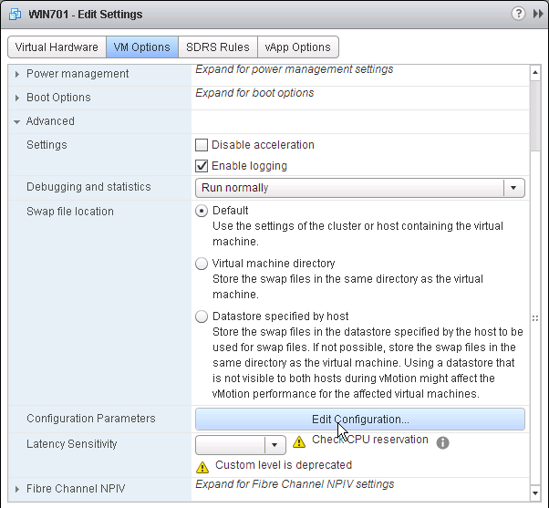
  5. Switch to the VM Options tab.
  6. In the Boot Options section, check the box to Force EFI Setup, or Force BIOS Setup.

  7. If vSphere, and booting from an ISO:
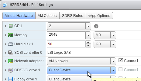
    1. Switch to the Virtual Hardware tab.
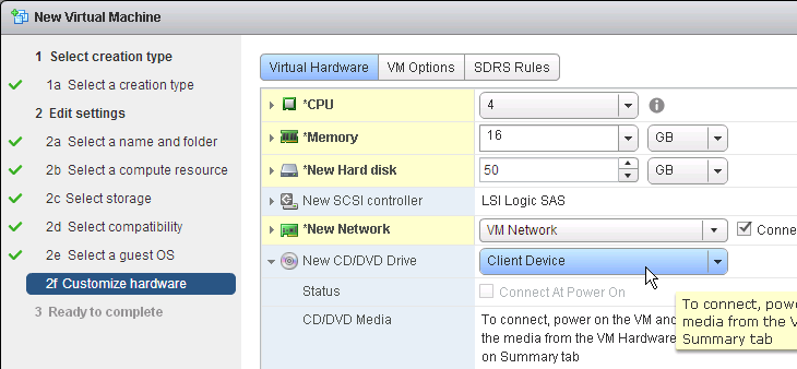
    2. Expand CD/DVD drive 1 and connect the virtual machine’s CD to the Datastore ISO File named PvSBoot.iso.
    3. Make you check Connect At Power On.
    4. Make sure the CD-ROM is IDE, and not SATA.
    5. Also, remove any SATA controller.
    6. Click OK to close the virtual machine settings.
  8. If Hyper-V:
    1. In VMM, edit the virtual machine properties
    2. Switch to the Hardware Configuration page.
    3. If booting from ISO, in the Virtual DVD drive page, assign the ISO from the library.
    4. Switch to the Hardware Configuration > Firmware page
    5. Move PXE Boot or IDE Hard Drive to the top.
    6. Click OK to close the virtual machine properties.
  9. Power on the virtual machine.
  10. If vSphere EFI:
    1. Boot the virtual machine.
    2. In the Boot Manager, don’t select a boot option. Instead, go to Enter Setup.
    3. Go to Configure boot options.
    4. Go to Change boot order.
    5. Press <Enter> on Change the order.
    6. Use the plus icon on your number pad to move EFI Network to the top.
    7. Commit changes and exit.
    8. Exit the Boot Maintenance Manager.
    9. Now boot from EFI Network.
  11. If vSphere BIOS:
    1. Boot the virtual machine.
    2. In the Virtual Machine’s console, on the Boot tab, move Network boot or CD-ROM Drive to the top.

    3. Press F10 to close the BIOS Setup Utility.
  12. You should see the virtual machine boot from a Citrix Provisioning server and find the vDisk.

  13. Once the machine has booted, login. If you see a Format Disk message, just ignore it, or click Cancel. The Imaging Wizard will format it for you.
  14. The conversion wizard will commence. It will take several minutes to copy the files from C: drive (local hypervisor disk) to vDisk (Citrix Provisioning disk) so be patient.

    1. If the Imaging Wizard does not successfully copy the local drives to the vDisk, first make sure the vDisk is mounted by opening the systray icon.

    2. Then you can manually start the conversion by running C:\Program Files\Citrix\Provisioning Services\P2PVS.exe.

  15. When done, click Done. It might prompt you to reboot. Reboot it, log in, and then shut it down.

Master Target Device – Join to Domain

Citrix Provisioning must learn the password of the Target Device’s Active Directory computer account. To achieve this, use the Citrix Provisioning Console to create or reset the computer account.

Do not use Active Directory Users & Computers to manage the Target Device computer account passwords. Creating, Resetting, and Deleting Target Device Active Directory computer objects must be done from inside the Citrix Provisioning Console so Citrix Provisioning will know the computer’s password. Citrix Provisioning will automatically handle periodic (default 7 days) changing of the computer passwords.

  1. In the Citrix Provisioning Console, right-click the new Target Device, expand Active Directory, and click Create Machine Account.
  2. Select the correct OU in which the Active Directory computer object will be placed, and click Create Account.
  3. Then click Close.

Boot from vDisk

  1. In the Citrix Provisioning Console, go to the Device Collection.
  2. Right-click the new device, and click Properties.
  3. On the General tab, set Boot from to vDisk.
  4. Restart the Target Device.
  5. At this point it should be booting from the vDisk. To confirm, in the systray by your clock is an icon that looks like a disk. Double-click it.
  6. The General tab shows it Boot from = vDisk, and the Mode = Read/Write.

vDisk – Save Clean Image

If you have not yet installed applications on this image, you can copy the VHDX file and keep it as a clean base image for future vDisks.

  1. If this vDisk is in Private Image mode, first power off any Target Devices that are accessing it.
  2. Then you can simply copy the VHDX file and store it in a different location.

If you later need to create a new vDisk, here’s how to start from the clean base image:

  1. Copy the clean base image VHDX file to a new folder.
  2. Rename the file to match your new Image name.
  3. In the Citrix Provisioning Console, create a new Store, and point it to the new folder.
  4. Give the new Store a name.
  5. On the Servers tab, select all Provisioning servers.
  6. On the Paths tab, enter the path to the new folder. Click OK.
  7. Click OK when asked to create the default write cache.
  8. Right-click the new store and click Add or Import Existing vDisk.
  9. Click Search.
  10. Click OK if prompted that a new property file will be created with default values.
  11. Click Add, click OK, and then click Close.

  12. You can now assign the new vDisk to an Updater Target Device and install applications.

KMS

Skip this section if you are using Active Directory-based Activation instead of KMS Server.

This only needs to be done once. More information at CTX128276 Configuring KMS Licensing for Windows and Office.

  1. Make sure the Citrix Provisioning services are running as an account that is a local administrator on the Provisioning Servers. Citrix Provisioning needs to mount the vDisk but only local administrators can mount VHDX files.
  2. In the Citrix Provisioning Console, right-click on the virtual disk, and select Properties.
  3. Click on the tab named Microsoft Volume Licensing, and set the licensing option to None. Click OK.
  4. Boot an Updater device from the vDisk in Private Image mode.
  5. Login to Windows and rearm the system for both Windows and Office, one after the other.
    1. For Windows Vista, 7, 2008, and 2008R2: Run cscript.exe slmgr.vbs -rearm
    2. For Office (for 64-bit client): C:\Program Files(x86)\Common Files\Microsoft shared\OfficeSoftwareProtectionPlatform\OSPPREARM.EXE
    3. For Office (for 32-bit client): C:\Program Files\Common Files\Microsoft shared\OfficeSoftwareProtectionPlatform\OSPPREARM.EXE
  6. A message is displayed to reboot the system, DO NOT REBOOT- Instead, run sealing tasks and then shut down the Target Device.
  7. In the Citrix Provisioning Console, right-click on the virtual disk, and select Properties.
  8. Click on the tab named Microsoft Volume Licensing, and set the licensing option to Key Management Services (KMS).
    • In Citrix Provisioning 1906 and newer, also check the box next to Accelerated Office Activation.
  9. Click OK.

Note: After streaming the vDisk to multiple Target Devices, Administrators can validate that the KMS configuration was successful by verifying that the CMID for each device is unique.

  • For Windows: Run cscript.exe slmgr.vbs –dlv
  • For Office: Run C:\Program Files\Microsoft Office\Office16\cscript ospp.vbs /dcmid

Also see Citrix Blog Post Demystifying KMS and Provisioning Services

vDisk – Seal

Do the following sealing steps every time you switch from Private Image mode to Standard Image mode, or promote a Maintenance Image to Test or Production.

  1. Run antivirus sealing tasks. See VDA > Antivirus for links to various antivirus vendor articles.
  2. Citrix Blog Post Sealing Steps After Updating a vDisk contains a list of commands to seal an image for Citrix Provisioning.
  3. Citrix Blog Post PVS Target Devices & the “Blue Screen of Death!” Rest Easy. We Can Fix That has a reg file to clear out DHCP configuration.
  4. Shut down the target device.
  5. Note: Base Image Script Framework (BIS-F) automates many sealing tasks. The script is configurable using Group Policy.

Defrag the vDisk

In the Citrix Blog Post Size Matters: PVS RAM Cache Overflow Sizing, Citrix recommends defragmenting the vDisk.

If the vDisk was created by App Layering ELM, then Gunther Anderson at Performance considarations? at Citrix Discussions says there’s no point in doing a defrag.

  1. While still in Private Image mode, right-click the vDisk, and click Mount vDisk.
  2. In File Explorer, find the mounted disk, right-click it, and click Properties.
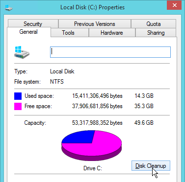
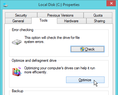
  3. On the Tools tab, click Optimize.
  4. Highlight the mounted drive and click Optimize.
  5. When done, back in Citrix Provisioning Console, right-click the vDisk, and click Unmount vDisk.

Standard Image Mode

  1. In the Citrix Provisioning Console, go to the vDisk store, right-click the vDisk, and click Properties.
  2. On the General tab:
    1. Change the Access Mode to Standard Image.
    2. Set the Cache Type to Cache in device RAM with overflow on hard disk. Don’t leave it set to the default cache type or you will have performance problems. Also, every time you change the vDisk from Standard Image to Private Image and back again, you’ll have to select Cache in device RAM with overflow on hard disk.
    3. Change the Maximum RAM size to a higher value. For virtual desktops, set it to 512 MB or larger. For Remote Desktop Session Hosts, set it to 4096 MB or lager. Make sure your Target Devices have extra RAM to accommodate the write cache.
    4. On the bottom of the General tab is a new checkbox to disable cleanup of cached secrets. By default, Citrix Provisioning 7.12 and newer will delete any cached credentials. This behavior can be disabled by checking the box.
  3. Click OK when done.

vDisk – High Availability

  1. In the Citrix Provisioning Console, right-click the vDisk, and click Load Balancing.
  2. Ensure Use the load balancing algorithm is selected. Check the box next to Rebalance Enabled. Click OK.
  3. Go to the physical vDisk store location (e.g. D:\Win2016Common) and copy the .vhd and .pvp vDisk files for the new vDisk. Do not copy the .lok file.
  4. Go to the same path on the other Provisioning Server and paste the files. You must keep both Provisioning Servers synchronized.
  5. Another method of copying the vDisk files is by using Robocopy:
    Robocopy D:\vDisks\ \\pvs2\d$\vDisks *.vhd *.avhd *.pvp *.vhdx *.avhdx /b /mir /xf *.lok /xd WriteCache /xo
  6. Citrix Blog Post The vDisk Replicator Utility is finally finished! has a GUI utility script that can replicate vDisks between Citrix Provisioning Sites and between Citrix Provisioning Farms.

  7. In the Citrix Provisioning Console, right-click the vDisk, and click Replication Status.
  8. Blue indicates that the vDisk is identical on all servers. If they’re not identical then you probably need to restart the Citrix PVS Stream Service and the Citrix PVS SOAP Service. Click Done when done.

Cache Disk – vSphere

Here are vSphere instructions to remove the original C: drive from the Master Target Device, and instead add a blank cache disk.

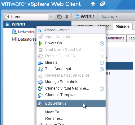
  1. In vSphere Client, right-click the Master Target Device, and click Edit Settings.
  2. Select Hard disk 1, and click the x icon. Click OK.
  3. Edit the Settings of the virtual machine again.
  4. On the top right, click Add New device, and select Hard Disk.
  5. This is your cache overflow disk. Size is based on the type of VDA.
    • 40 GB is probably a good size for session hosts.
    • For virtual desktops this can be a smaller disk (e.g. 5 GB).
    • Note: the pagefile must be smaller than the cache disk.
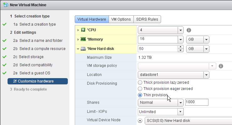
  6. Expand the newly added disk, and set Disk Provisioning to Thin provision if desired. Click OK when done.
  7. Configure group policy to place the Event Logs on the cache disk.
  8. Boot the Target Device and Verify the Write Cache Location.

Cache Disk – Hyper-V

Remove the original C: drive from the Target Device and instead add a cache disk.

  1. Edit the settings of your Citrix Provisioning master virtual machine and remove the existing VHD.
  2. Make a choice regarding deletion of the file.
  3. Create a new Disk.
  4. This is your cache overflow disk. 15-20 GB is probably a good size for session hosts. For virtual desktops this can be a smaller disk (e.g. 5 GB). Note: the pagefile must be smaller than the cache disk. Click OK when done.
  5. Configure group policy to place the Event Logs on the cache disk.

Verify Write Cache Location

  1. Boot the target device virtual machine.
  2. Open the Virtual Disk Status window by clicking the Citrix Provisioning disk icon in the system tray by the clock.
  3. Make sure Mode is set to Read Only and Cache type is set to  device RAM with overflow on local hard drive.
  4. If Cache type says server, then follow the next steps:

    1. For the cache disk, if machine uses BIOS, then only MBR is supported. GPT only works with EFI/UEFI machines.
    2. The cache disk must be a Basic disk, not Dynamic.
    3. Format the cache disk with NTFS.
    4. Make sure the pagefile is smaller than the cache disk. If not it will fail back to server caching.
  5. After fixing the problem and rebooting, the Cache Type should be device RAM with overflow on local hard drive.
  6. To view the files on the cache disk, go to Folder Options, and deselect Hide protected operating system files.
  7. On the cache disk, you’ll see the pagefile, and the vdiskdiff.vhdx file, which is the overflow cache file.

Related Pages

Citrix Provisioning Master Device – Preparation

Last Modified: Oct 16, 2024 @ 6:13 am

Navigation

This article applies to all 7.x versions of Citrix Provisioning, including 2407, 2402 LTSR, and 2203 LTSR.

💡 = Recently Updated

Change Log

General Preparation

  1. In Provisioning 2311 and newer, make sure the VDA machine is UEFI instead of BIOS. If not, see Converting BIOS vDisks to UEFI at Citrix Docs.
  2. Build the VDA like normal.
  3. Update VMware Tools.
  4. Join the machine to the domain.
  5. Chrome and Edge – CTX212545 PVS 7.6 CU1: Write cache getting filled up automatically recommends disabling Google Chrome automatic updates.

Pagefile

Ensure the pagefile is smaller than the cache disk. For example, if you allocate 20 GB of RAM to your Remote Desktop Session Host, and if the cache disk is only 15 GB, then Windows will have a default pagefile size of 20 GB and Citrix Provisioning will be unable to move it to the cache disk. This causes Citrix Provisioning to cache to server instead of caching to your local cache disk (or RAM).

The cache disk size for a session host is typically 15-20 GB. The cache disk size for a virtual desktop is typically 5 GB.

  1. Open System. In 2012 R2 and newer, you can right-click the Start button, and click System.
  2. For older versions of Windows, you can click Start, right-click the Computer icon, and click Properties. Or find System in the Control Panel.
  3. Click Advanced system settings.
  4. On the Advanced tab, click the top Settings button.
  5. On the Advanced tab, click Change.
  6. Either turn off the pagefile or set the pagefile to be smaller than the cache disk. Don’t leave it set to System managed size. Don’t forget to click the Set button. Click OK several times.

VMware ESXi/vSphere

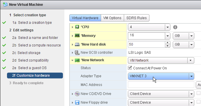
VMXNET3

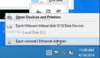
E1000 is not supported – For VMware virtual machine, make sure the NIC is VMXNET3. E1000 is not supported and will affect performance.

View hidden adapters in Device Manager and delete any ghost VMXNET3 NICs.

  1. At the command prompt, type the following lines, pressing ENTER after each line
    set devmgr_show_nonpresent_devices=1
    start devmgmt.msc
    
  2. Open the View menu, and click Show hidden devices.
  3. Expand Network adapters, and look for ghost NICs (grayed out). If you see any, remove them.

SATA Controller

Citrix Provisioning does not support the SATA Controller that became available in ESXi virtual machine hardware Version 10. Change the CD/DVD Drive to IDE instead of SATA.

Then remove the SATA Controller.

NTP

Ensure that the ESXi hosts have NTP enabled.

DHCP

After creating the vDisk, follow the instructions at Provisioning Services 6 Black Screen Issue to clear any DHCP address in the vDisk.

Slow Boot Times

Citrix Provisioning Target Devices in VMware ESX boot slow intermittently after upgrading the ESX hosts from 5.0 to 5.1.

Citrix CTX139498 Provisioning Services Target Devices Boot Slow in ESX 5.x: Use the following command to disable the NetQueue feature on the ESX hosts:

esxcli system settings kernel set -s netNetqueueEnabled -v FALSE

Hyper-V

  1. Generation 2 support is available in Citrix Provisioning 7.8 and newer.
  2. If Generation 1, each Hyper-V Citrix Provisioning Target Device must have a Legacy network adapter. Legacy NIC supports Network Boot, while the Synthetic NIC does not.
  3. Give the Legacy Network Adapter a Static MAC address. If you leave it set to all zeros then VMM will generate one once the VM is deployed.
  4. When you reopen the virtual machine properties there will be a Static MAC address.
  5. Set the Action to take when the virtualization server stops to Turn off virtual machine. This prevents Hyper-V from creating a BIN file for each virtual machine.
  6. To set a VLAN, either create a Logical Network and Network Site.
  7. Or use Hyper-V Manager to set the VLAN on each virtual machine NIC.

Antivirus Best Practices

Citrix’s Recommended Antivirus Exclusions

Citrix Tech Zone: Endpoint Security, Antivirus, and Antimalware Best Practices.

Citrix Blog Post Citrix Recommended Antivirus Exclusions: the goal here is to provide you with a consolidated list of recommended antivirus exclusions for your Citrix virtualization environment focused on the key processes, folders, and files that we have seen cause issues in the field:

  • Set real-time scanning to scan local drives only and not network drives
  • Disable scan on boot
  • Remove any unnecessary antivirus related entries from the Run key
  • Exclude the pagefile(s) from being scanned
  • Exclude Windows event logs from being scanned
  • Exclude IIS log files from being scanned

See the Blog Post for exclusions for each Citrix component/product including StoreFront, VDA, Controller, and Provisioning. The Blog Post also has links to additional KB articles on antivirus.

Sophos

Sophos Anti-Virus for Windows 2000+: incorporating current versions in a disk image, including for use with cloned virtual machines: This procedure will make sure that the produced target/cloned computers:

  • Get their distinct identity with Enterprise Console, under which they can be subsequently managed.
  • Have the desired version of Sophos Anti-Virus already installed and configured on the created image.

Kaspersky

CTX217997 BSOD Error: “STOP 0x0000007E CVhdMp.sys with Kaspersky antivirus: install Kaspersky Light Agent using the /pINSTALLONPVS=1 switch.

Boot ISO

You can create a Citrix Provisioning boot ISO for your Target Devices. This is an alternative to PXE.

  1. On the Provisioning server, run Citrix Provisioning Boot Device Manager.
  2. In the Specify the Login Server page, add the IP addresses of Provisioning servers.
  3. Check the box next to Target device is UEFI firmware. Click Next.
  4. In the Set Options page, check the box next to Verbose Mode, and click Next.
  5. In the Burn the Boot Device page, do not click Burn. If you do, then you will have a very bad day. Instead, look in the Boot Device section, and change it to Citrix ISO Image Recorder. Then you can click Burn.
  6. Save the iso and upload it to a datastore or VMM library.
  7. You can now configure your Target Devices to boot from this ISO file.

Target Device Software Installation

The Target Device Software version must be the same or older than the Citrix Provisioning server version.

The install instructions for all Target Device versions 2407 and older are essentially the same.

Do the following on the master VDA you intend to convert to a vDisk. Try not to install this while connected using RDP or ICA since the installer will disconnect the NIC.

  1. Ghost NICs – Your Target Device might have ghost NICs. This is very likely to occur on Windows 7 and Windows 2008 R2 VMs when using VMXNet3. Follow CTX133188 Event ID 7026 – The following boot-start or system-start driver(s) failed to load: Bnistack to view hidden devices and remove ghost NICs.
  2. Go to the downloaded Citrix Provisioning and run PVS_Device_x64.exe.
  3. If you see a requirements window, then click Install to install prerequisites.
  4. In the Welcome to the Installation Wizard for Citrix Provisioning Target Device x64 page, click Next.
  5. In the License Agreement page, select I accept, and click Next.
  6. In the Customer Information page, click Next.
  7. In the Destination Folder page, click Next.
  8. In the Ready to Install the Program page, click Install.
  9. In the Installation Wizard Completed page click Finish.
  10. Click Yes if prompted to restart.
  11. The Imaging Wizard launches. Review the following tweaks. Then proceed to converting the Master Image to a vDisk.

Target Device Software Tweaks

Asynchronous I/O

Prevent Drive for Write Cache

From Citrix Community PVS Target Device wrong drive letters: The driver that determines which partition to place the local cache searches for a file named: {9E9023A4-7674-41be-8D71-B6C9158313EF}.VDESK.VOL.GUID in the root directory. If the file is found it will not place the write cache on that disk.

Excessive Retries

If VMware vSphere, make sure the NIC is VMXNET3.

Hide Citrix Provisioning Systray Icon

From Citrix CTX572340 Hide “Virtual Disk status” icon from System tray on the endpoints: Add the reg value below:

  • HKLM\Software\Citrix\ProvisioningServices\StatusTray
    • ShowIcon (DWORD) = 0

This however will disable to all users, even Admins. Solution: Apply the HKCU key below based on Group membership (Group Policy Preferences > Item Level Targeting):

  • HKEY_CURRENT_USER\SOFTWARE\Citrix\ProvisioningServices\StatusTray
    • ShowIcon (DWORD) = 0

Once that is in place the icon will go away.

Related Pages

Citrix Provisioning Console Configuration

Last Modified: Oct 16, 2024 @ 6:13 am

Navigation

This article applies to all 7.x versions of Citrix Provisioning, including 2407, 2402 LTSR, and 2203 LTSR.

Change Log

Launch the Provisioning Console

  1. Launch the Citrix Provisioning Console.
  2. Right-click the top-left node and click Connect to Farm.
  3. Enter localhost and click Connect.
  4. In large multi-domain environments, or when older domains are still configured but are unreachable, if you see Server communication timeout, then see CTX231194 PVS Console Errors: “Critical Error: Server communication timeout” for a registry key to skip forest level trusts, a registry key to increase the console timeout, and a .json file to blacklist domains.

Farm Properties

  1. Right-click the farm name and click Properties.
  2. On the Groups tab, add the Citrix Admins group.
  3. On the Security tab, add the Citrix Administrators group to grant it full permission to the entire Provisioning farm. You can also assign permissions in various nodes in the Provisioning console. Citrix Provisioning 2311 and newer let you restrict a group to Read-only access.
  4. On the Options tab, check the boxes next to Enable Auditing, and Enable offline database support.

    • With Auditing enabled, you can right-click on objects and click Audit Trail to view the configuration changes.

  5. If you see a Problem Report tab, you can enter MyCitrix credentials. This tab was removed in Provisioning 2209.
  6. Registration tab shows you if the farm is registered to a CVAD Site or Citrix Cloud.

  7. Encryption tab shows you the status of database encryption. In PVS 2407 and newer, database encryption no longer requires registration with Citrix Cloud.
  8. Click OK to close Farm Properties.
  9. Click OK when prompted that a restart of the service is required.

Server Properties

  1. Expand the Provisioning Site and click Servers.
  2. For each Provisioning Server, right-click it, and click Configure Bootstrap.
  3. Click Read Servers from Database. This should cause both servers to appear in the list.
  4. From Carl Fallis at PVS HA at Citrix Discussions: when stopping the stream service through the console the Provisioning server will send a message to the targets to reconnect to another server before the stream service shuts down. The target then uses the list of login servers (Bootstrap servers) and reconnects to another server, this is almost instantaneous failover and can’t really be detect . In the case of the Provisioning server failing the target detects it and reconnects, slightly different mechanism and the target may hang for a short time. Check out the following article for more information https://www.citrix.com/blogs/2014/10/16/provisioning-services-failover-myth-busted for the Provisioning server failure case.
  5. On the Options tab, check the box next to Verbose mode.
  6. Right-click the server, and click Properties.
  7. On the General tab, check the box next to Log events to the server’s Windows Event Log.
  8. Click Advanced.
  9. Citrix Blog Post From Legacy to Leading Edge: The New Citrix Provisioning Guidelines says Avoid Modifying the Threads Per Port and Streaming Ports. The old guidance was for the number of threads per port should match the number of vCPUs assigned to the server.
  10. On the same tab are concurrent I/O limits. Note that these throttle connections to local (drive letter) or remote (UNC path) storage. Setting them to 0 turns off the throttling. Only testing will determine the optimal number.
  11. Click OK to close Advanced Server Properties.
  12. On the Network tab, Citrix Blog Post From Legacy to Leading Edge: The New Citrix Provisioning Guidelines says Avoid Modifying the Threads Per Port and Streaming Ports. The old guidance was to change the Last port to 6968.
    • Note: port 6969 is used by the Provisioning two-stage boot (Boot ISO) component.
    • You can set the First port to 7000 to avoid port 6969 and get more ports.
    • Citrix Provisioning 1811 and newer open Windows Firewall ports during installation, but Citrix Provisioning Console will not change the Windows Firewall rules based on what you configure here. You’ll need to adjust the Windows Firewall rules manually.
  13. Click OK when done.
  14. Click Yes if prompted to restart the stream service.
  15. If you get an error message about the stream service then you’ll need to restart it manually.

  16. From Carl Fallis at PVS HA at Citrix Discussions: when stopping the stream service through the console the Provisioning server will send a message to the targets to reconnect to another server before the stream service shuts down. The target then uses the list of login servers and reconnects to another server, this is almost instantaneous failover and can’t really be detect . In the case of the Provisioning server failing the target detects it and reconnects, slightly different mechanism and the target may hang for a short time. Check out the following article for more information https://www.citrix.com/blogs/2014/10/16/provisioning-services-failover-myth-busted for the Provisioning server failure case.
  17. Repeat for the other servers. You can copy the Server Properties from the first server, and paste them to additional servers.


Create vDisk Stores

To create additional vDisk stores (one per vDisk / Delivery Group / Image), do the following:

  1. On the Provisioning servers, using Explorer, go to the local disk containing the vDisk folders and create a new folder. The folder name usually matches the vDisk name. Do this on both Provisioning servers.
  2. In the Provisioning Console, right-click Stores, and click Create Store.
  3. Enter the name for the vDisk store, and select an existing site.
  4. Switch to the Servers tab. Check the boxes next to the Provisioning Servers.
  5. On the Paths tab, enter the path for the Delivery Group’s vDisk files. Shared SMB paths are supported as described at Citrix Blog Post PVS Internals #4: vDisk Stores and SMB3.
  6. Click Validate.
  7. Click Close and then click OK.
  8. Click Yes when asked for the location of write caches.

Create Device Collections

  1. Expand the site, right-click Device Collections, and click Create Device Collection.
  2. Name the collection in some fashion related to the name of the Delivery Group, and click OK.

If you are migrating from one Provisioning farm to another, see Kyle Wise How To Migrate PVS Target Devices.

Prevent “No vDisk Found” PXE Message

If PXE is enabled on your Provisioning servers, and if you PXE boot a machine that is not added as a device in the Provisioning console, then the machine will pause booting with a “No vDisk Found” message at the BIOS boot screen. Do the following to prevent this.

  1. Enable the Auto-Add feature in the farm Properties on the Options tab.

  2. Create a small dummy vDisk (e.g. 100 MB).

  3. Create a dummy Device Collection.

  4. Create a dummy device.
  5. Set it to boot from Hard Disk
  6. Assign the dummy vDisk and click OK.
  7. Set the dummy device as the Template.

  8. Right-click the site, and click Properties.
  9. On the Options tab, point the Auto-Add feature to Dummy collection, and click OK.

Related Topics

Citrix Provisioning 2407 – Server Install

Last Modified: Oct 16, 2024 @ 6:15 am

Navigation

This article applies to all 7.x versions of Citrix Provisioning, including 2407, 2402 LTSR, and 2203 LTSR.

💡 = Recently Updated

Change Log

Planning and Versions

CTX220651 Best Practices for deploying PVS in multi-geo environments: ensure that Provisioning farms do not span data centers with a network latency that can affect communications between the Provisioning Servers and the SQL database

SQL 2019 is supported with Citrix Provisioning 2003 and newer.

Citrix Provisioning Firewall Rules

The most recent Current Release version of Citrix Provisioning is 2407.

For LTSR CVAD, deploy the Citrix Provisioning version that matches your CVAD version:

Citrix License Server Version

Upgrade the Citrix Licensing server to the latest version. Citrix now requires the latest License Server version and is configured to upload license telemetry data.

Upgrade

Windows Server 2022 is supported with Citrix Provisioning 2203 and newer.

VMware ESXi 8.0 is supported with Citrix Provisioning 2212 and newer.

SCVMM 2022 is supported with Citrix Provisioning 2203 and newer.

If you are upgrading from an older version of Citrix Provisioning, do the following:

  1. In-place upgrade the Citrix License Server.
  2. In-place upgrade the Provisioning Console.
    1. Re-register the Citrix.PVS.snapin.dll snap-in:
      "C:\Windows\Microsoft.NET\Framework64\v4.0.30319\InstallUtil.exe" "c:\program files\citrix\provisioning services console\Citrix.PVS.snapin.dll"
    2. If upgrading from 7.15.3000 to 7.15.4000, then manually upgrade the snap-ins. See CTX256773 Powershell SnapIns are not upgraded from PVS 7.15 LTSR CU3 to 7.15 LTSR CU4 after the upgrade is complete
  3. In-place upgrade the Provisioning Server. If you have two or more Provisioning servers, upgrade one, and then the other. If High Availability is configured correctly, then the Target Devices should move to a different Provisioning server while a Provisioning server is being upgraded.
    1. After the first Provisioning server is upgraded, run the Configuration Wizard. You can generally just click Next through the wizard. At the end, you’ll be prompted to upgrade the database. Then upgrade the remaining Provisioning servers and run the Config Wizard on each of them too.
  4. Upgrade the Target Device Software inside each vDisk. Don’t do this until the Provisioning servers are upgraded (Target Device Software must be same version or older than the Provisioning Servers).
    1. If your Target Devices are 7.6.1 or newer, you can create a Maintenance version, boot an Updater Target Device, and in-place upgrade the Target Device Software.
    2. If your Target Devices are older, then you must reverse image.

vDisk Storage

Do the following on both Provisioning Servers. The vDisks will be stored locally on both servers. You must synchronize the files on the two servers: either manually (e.g. Robocopy), or automatically (e.g. DFS Replication).

Create D: Drive

  1. In the vSphere Web Client, edit the settings for each of the Provisioning server virtual machines.
  2. On the bottom, use the drop-down list to select New Hard Disk, and click Add.
  3. Expand the New Hard disk by clicking the arrow next to it.
  4. Change the disk size to 500 GB or higher. It needs to be large enough to store the vDisks. Each full vDisk is 40 GB plus a chain of snapshots. Additional space is needed to merge the chain.
  5. Feel free to select Thin provision, if desired. Click OK when done.
  6. Login to the session host. Right-click the Start Button, and click Disk Management.
  7. In the Action menu, click Rescan Disks.
  8. On the bottom right, right-click the CD-ROM partition, and click Change Drive Letters and Paths.

  9. Click Change.
  10. Change the drive letter to E:, and click OK.
  11. Click Yes when asked to continue.
  12. Right-click Disk 1 and click Online.
  13. Right-click Disk 1 and click Initialize Disk.
  14. Click OK to initialize the disk.
  15. Right-click the Unallocated space, and click New Simple Volume.
  16. In the Welcome to the New Simple Volume Wizard page, click Next.
  17. In the Specify Volume Size page, click Next.
  18. In the Assign Drive Letter or Path page, select D: and click Next.
  19. In the Format Partition page, change the Volume label to vDisks and click Next.
  20. In the Completing the New Simple Volume Wizard page, click Finish.
  21. If you see a pop-up asking you to format the disk, click Cancel since Disk Management is already doing that.

vDisk Folders

On the new D: partition, create one folder per Delivery Group. For example, create one called Win10Common, and create another folder called Win10SAP. Each vDisk is composed of several files, so its best to place each vDisk in a separate folder. Each Delivery Group is usually a different vDisk.

Robocopy Script

Here is a sample robocopy statement to copy vDisk files from one Provisioning server to another. It excludes .lok files and excludes the WriteCache folders.

REM Robocopy from PVS01 to PVS02
REM Deletes files from other server if not present on local server
Robocopy D:\vDisks \\pvs02\d$\vDisks *.vhd *.vhdx *.avhd *.avhdx *.pvp /b /mir /xf *.lok /xd WriteCache /xo

Citrix Blog Post vDisk Replicator Utility has a GUI utility script that can replicate vDisks between Provisioning Sites and between Provisioning Farms.

Service Account

Provisioning Services should run as a domain account that is in the local administrators group on both Provisioning servers. This is required for KMS Licensing.

Provisioning Console Install/Upgrade

The installation and administration of Citrix Provisioning 2407 and older (including LTSR versions 2203 and 1912) are essentially identical.

Operating System – Windows Server 2022 is supported with Citrix Provisioning 2203 and newer.

Hypervisor – VMware ESXi 8.0 is supported with Citrix Provisioning 2212 and newer. VMware VSAN 8 is supported with Citrix Provisioning 2311 and newer.

BIOS – Citrix Provisioning 2311 and newer no longer support BIOS. See Converting BIOS vDisks to UEFI at Citrix Docs.

If you want to automate the installation and configuration of Citrix Provisioning, see Dennis Span Citrix Provisioning Server unattended installation.

To manually install Provisioning Console, or in-place upgrade the Provisioning Console:

  1. Go to the downloaded Citrix Provisioning, and in the Console folder, run PVS_Console_x64.exe.
  2. Click Install.
  3. If you see the .NET Framework Setup page:
    1. Check the box next to I have read and accept the license terms, and click Install.
    2. In the Installation Is Complete page, click Finish.
    3. Click Restart Now.
    4. Restart the PVS_Console_x64.exe installer.
    5. Click Install.
  4. Click Yes to reboot when prompted. Then restart the installation.
  5. In the Welcome to the InstallShield Wizard for Citrix Provisioning Console x64 page, click Next.
  6. In the License Agreement page, select I accept the terms, and click Next.
  7. In the Customer Information page, click Next.
  8. In the Destination Folder page, click Next.
  9. In the Ready to Install the Program page, click Install.
  10. In the InstallShield Wizard Completed page, click Finish.
  11. Click Yes if you are prompted to restart.

After upgrading the Console, re-register the PowerShell snap-in. This is required for the Citrix App Layering Agent.

"C:\Windows\Microsoft.NET\Framework64\v4.0.30319\InstallUtil.exe" "c:\program files\citrix\provisioning services console\Citrix.PVS.snapin.dll"

Provisioning Server – Install/Upgrade

The installation and administration of Citrix Provisioning 2407, 1912 LTSR CU9, 7.15.45, 7.6.9 and other 7.x versions are essentially identical.

Operating System – Windows Server 2022 is supported with Citrix Provisioning 2203 and newer.

Hypervisor – VMware ESXi 8.0 is supported with Citrix Provisioning 2212 and newer. VMware VSAN 8 is supported with Citrix Provisioning 2311 and newer.
BIOS – Citrix Provisioning 2311 and newer no longer support BIOS. See Converting BIOS vDisks to UEFI at Citrix Docs.

You can in-place upgrade Provisioning Server. The Provisioning Servers must be upgraded before the vDisks’ Target Device Software are upgraded. While upgrading one Provisioning Server, all Target Devices are moved to the other Provisioning Server assuming that vDisk High Availability is properly configured.

To install/upgrade Provisioning server:

  1. If vSphere, make sure the Provisioning server virtual machine Network Adapter Type is VMXNET 3.
  2. Go to the downloaded Provisioning ISO, and in the Server folder, run PVS_Server_x64.exe.
  3. Click Install when asked to install prerequisites.
  4. Click Yes to reboot. After the restart, relaunch the installer.
  5. Note: there’s a long delay before the installation wizard appears.
  6. In the Welcome to the Installation Wizard for Citrix Provisioning Server x64 page, click Next.
  7. In the License Agreement page, select I accept the terms, and click Next.
  8. In Citrix Provisioning 1811 and newer, you’ll see a Default Firewall Ports page. You can optionally select Automatically open all Citrix Provisioning ports in Windows Firewall. If you later use the Citrix Provisioning Console to change the ports, then the Windows Firewall rules need to be adjusted manually since the Citrix Provisioning Console won’t do it for you.
  9. In the Customer Information page, select Anyone who users this computer, and click Next.
  10. In the Destination Folder page, click Next.
  11. In the Ready to Install the Program page, click Install.
  12. In the Installation Wizard Completed page, click Finish.

Database Script

By default, the Citrix Provisioning Configuration Wizard will try to create the database using the credentials of the person that is running the Wizard. This isn’t always feasible. An alternative is to create a script that a DBA can run on the SQL server.

  1. Go to C:\Program Files\Citrix\Provisioning Services and run DBScript.exe.
  2. Change the selection to New database for 2012 or higher.
  3. Enter a path to save the script file.
  4. Fill in the other fields.
  5. Select an Active Directory group containing your Citrix administrators, and click OK.
  6. In SQL Server Management Studio, open the SQL script.

  7. Execute the script to create the database.

  8. The person that runs the Citrix Provisioning Configuration Wizard will need db_owner permission to the new Citrix Provisioning database.
  9. Create a Windows service account that will run the services on the Citrix Provisioning server. This account must have a SQL login on the SQL server containing the Citrix Provisioning database. The Citrix Provisioning Configuration Wizard will grant this account the correct permissions in the database.

Configuration Wizard – New Farm

  1. If you used DBScript.exe to pre-create the database, skip to Configuration Wizard – Join Farm.
  2. Certificate – Joining PVS to CVAD site requires a valid certificate on the PVS server.
  3. For SQL AlwaysOn Availability Group, see CTX201203 SQL Server AlwaysOn Configuration for PVS 7.6. In summary: Use the wizard to create the database instance. In SQL, create the Availability Group. Then reconfigure Citrix Provisioning Server to point to the SQL AlwaysOn listener.
  4. The Citrix Provisioning Configuration Wizard launches automatically. If the database wasn’t pre-created, then the person running the wizard must have dbcreator and securityadmin roles on the SQL Server. If true, click Next. If not true, then cancel the wizard and launch it as somebody that does have those roles.

  5. The DHCP Services page appears. DHCP is typically hosted on a different server so select The service that runs on another computer. It is also possible to install DHCP on the Provisioning Servers. Click Next.
  6. In the PXE Services page, if you intend to use Boot Device Manager (BDM or ISO) instead of PXE, then change the selection to The service that runs on another computer, which disables the PXE service.
  7. If your Target Devices and Provisioning Servers are on the same broadcast network, then change the selection to Citrix Provisioning PXE service on this computer.
  8. Click Next.

  9. In the Farm Configuration page, choose Create Farm, and click Next.
  10. In the Database Server page, enter the name of the SQL server. Citrix Provisioning 2203 and newer has an option for specifying credentials to the SQL server.

    • In Citrix Provisioning 2203 and newer, click the Connection Options button and there’s an option for Enable MultiSubnetFailover for SQL Always On. There’s also an Optional TCP port field. Click OK and then click Next.
    • Older versions of Provisioning have an option for MultiSubnetFailover on the Database Server page. Click Next.
  11. In the New Farm page, enter the following:
    • Enter a descriptive Database name. Put the word Citrix in the database name so the DBA knows what it is for.
    • Enter a descriptive Farm name.
    • Enter a descriptive Site name.
    • Enter a descriptive Collection name. All of these names can be changed later.
    • Select the Active Directory group that will have administrator permissions to Citrix Provisioning, and click Next. If you don’t see your group here, select any group you belong to, and you can fix it later in the console.
  12. In the New Store page, browse to one of the vDisk folders, and give the store a name. Then click Next.
  13. You can optionally join the Provisioning Farm to CVAD or Citrix Cloud so that you can use Web Studio to provision Targets. The CVAD option is available in Citrix Provisioning 2311 and newer.

    1. Click Yes to join the farm to a CVAD Site.
    2. In the Citrix Virtual Desktops Controller page, click Next.
    3. Later in the wizard, an SSL certificate is required on the PVS server.
    4. The Registration tab in Provisioning Console > Farm Properties shows the status of CVAD Site registration.
  14. In the License Server page, enter the name of your Citrix license server, check the box next to Validate license server communication, and click Next.
  15. In the User account page, notice it defaults to Network service account. This won’t work with KMS licensing so change it to Specified user account. Enter credentials for an account that is a local administrator on all Provisioning servers, and click Next. Note: Provisioning 7.16 and newer support Group Managed Service Accounts.

  16. In the Active Directory Computer Account Password page, check the box, and click Next.
  17. In the Network Communications page, click Next.
  18. In the TFTP Option and Bootstrap Location page, check the box, and click Next.
  19. In the Stream Servers Boot List page, click Advanced.
  20. Check the box next to Verbose mode, click OK, and then click Next.
  21. If Provisioning 7.12 or newer, in the SSL Configuration page, click Next.
  22. If you see the Problem Report Configuration page, enter your MyCitrix credentials and click Next.
  23. In the Finish page, click Finish.
  24. If you are upgrading, then you might be asked to upgrade the database. Click Yes.
  25. Click OK if you see the firewall message.
  26. In the Finish page, click Done.

From Running the Configuration Wizard silently at Citrix Docs: Now that you have a configured server, you can run "C:\Program Files\Citrix\Provisioning Services\ConfigWizard.exe" /s to produce an .ans file at "C:\ProgramData\Citrix\Provisioning Services\ConfigWizard.ans". This .ans file can be modified and copied to additional Provisioning servers. "C:\Program Files\Citrix\Provisioning Services\ConfigWizard.exe" /a reads the .ans file and applies the configuration silently.

Configuration Wizard – Join Farm

  1. The Configuration Wizard launches automatically.
  2. There are two methods of handling SQL permissions:
    1. The person running the wizard must have db_owner on the database and securityadmin role on the SQL Server. This allows the wizard to add the service account to SQL logins and grant it access to the database.
    2. Or the person running the wizard can be limited to just db_owner permission to the database. The service account must be added manually to SQL logins by a DBA.
  3. The DHCP Services page appears. DHCP is typically hosted on a different server so select The service that runs on another computer. It is also possible to install DHCP on the Provisioning Servers. Click Next.
  4. In the PXE Services page, if you intend to use Boot Device Manager (BDM or ISO) instead of PXE, then change the selection to The service that runs on another computer, which disables the PXE service.
  5. If your Target Devices and Provisioning Servers are on the same broadcast network, then change the selection to Citrix Provisioning PXE service on this computer.
  6. Click Next.

  7. In the Farm Configuration page, click Join existing farm.
  8. In the Database Server page, enter the name of the SQL server. Citrix Provisioning 2203 and newer has an option for specifying credentials to the SQL server.

    • In Citrix Provisioning 2203 and newer, click the Connection Options button and there’s an option for Enable MultiSubnetFailover for SQL Always On. There’s also an Optional TCP port field. Click OK and then click Next.
    • Older versions of Provisioning have an option for MultiSubnetFailover on the Database Server page. Click Next.
  9. In the Existing Farm page, select the database, and click Next.
  10. In the Site page, select an existing site, and click Next.
  11. If you used the script to create the database, then there probably are no stores defined. Do so now.
  12. Otherwise, in the New Store page, select the existing store, and click Next.
  13. In the License Server page, click Next.
  14. In the User account page, notice it defaults to Network service account. This won’t work with KMS licensing so change it to Specified user account. Enter credentials for an account that is a local administrator on all Provisioning servers, and click Next. Note: Provisioning 7.16 and newer support Group Managed Service Accounts.

  15. In the Active Directory Computer Account Password page, check the box, and click Next.
  16. In the Network Communications page, click Next.
  17. In the TFTP Option and Bootstrap Location page, check the box, and click Next.
  18. In the Stream Servers Boot List page, click Advanced.
  19. Check the box next to Verbose mode, click OK, and then click Next.
  20. If Provisioning 7.12 or newer, in the Soap SSL Configuration page, click Next.
  21. If Provisioning 7.11 or newer, in the Problem Report Configuration page, enter your MyCitrix credentials, and click Next.
  22. In the Finish page, click Finish.
  23. Click OK if you see the firewall message.
  24. In the Finish page, click Done.

Troubleshooting – Networking Services Don’t Work After Reboot

If your PXE service or TFTP service does not work after a reboot of the Provisioning server, do the following:

  1. One option is to set the Citrix PVS PXE Service, Citrix PVS TFTP Service, and Citrix PVS Two-stage boot Service to Automatic (Delayed Start).
  2. The TFTP and Two-stage Boot services can be delayed by setting registry keys.
    • Keys = HKLM\System\CurrentControlSet\services\BNTFTP (and PVSTSB)\Parameters
    • Value = InitTimeoutSec (DWORD). 1 – 4 seconds. Default is 1.
    • Value = MaxBindRetry (DWORD). 5 – 20 retries. Default is 5.

Disable Firewall

Disable the Windows Firewall to allow communication to all Citrix Provisioning Server ports. Or, see Citrix Provisioning Firewall Rules and manually open all required ports. If you change the ports in the Citrix Provisioning Console, then you’ll need to adjust the Windows Firewall rules accordingly.

  1. In Server Manager, click Tools, and click Windows Firewall with Advanced Security.
  2. Click Windows Firewall Properties.
  3. On the Domain Profile tab, change the Firewall state to Off.

Disable BIOS Boot Menu

The versioning process in Citrix Provisioning will present a boot menu when booting any version except Production.

  1. To avoid this, create the DWORD registry value HKLM\Software\Citrix\ProvisioningServices\StreamProcess\SkipBootMenu on both Provisioning Servers and set it to 1. Note: the location of this key changed in Provisioning Services 7.0 and newer.
  2. Then restart the Citrix PVS Stream Service.

Private Mode vDisk – No Servers Available for vDisk

Citrix CTX200233 – Error: “No servers available for disk”: When you set a vDisk to Private Image mode (or new Maintenance version), if the Target Device is not connected to the server that contains the vDisk then you might see a message saying “No Servers Available for vDisk”.

  1. To avoid this, create the DWORD registry value HKLM\Software\Citrix\ProvisioningServices\StreamProcess\SkipRIMSForPrivate on both Provisioning Servers and set it to 1. Note: the location of this key changed in Provisioning Services 7.0.
  2. Then restart the Citrix PVS Stream Service.

Multi-Homed Provisioning Server

From slide 20 of http://www.slideshare.net/davidmcg/implementing-and-troubleshooting-pvs:, Multi-homed Provisioning server is not recommended but if you insist, and if running Provisioning 6.1 or older, configure the following. Provisioning 7.7 configuration wizard should have asked you for the management NIC.

  • HKLM\Software\Citrix\ProvisioningServices\IPC
    • New Reg_Sz (string) named IPv4Address with the IP of the NIC for IPC
  • HKLM\Software\Citrix\ProvisioningServices\Manager
    • New Reg_Sz (string) named GeneralInetAddr with the IP of the NIC and port
    • e.g. 10.1.1.2:6909

Citrix 133877 Timeout Error 4002 in Provisioning Server Console after Clicking “Show Connected Devices: when there are multiple streaming NICs assigned to the Provisioning Server, when Show Connected Devices was clicked in the Provisioning console, the following symptoms might be experienced: Server timeout error 4002, unusual delay of 3 to 4 minutes to list the connected devices, or Provisioning console stops responding. Complete the following to resolve the issue:

  1. On the Provisioning Server machine, under HKLM\software\citrix\provisioningServices\Manager key, create registry DWORD RelayedRequestReplyTimeoutMilliseconds, and set it to 50 ms (Decimal).
  2. Create a DWORD RelayedRequestTryTimes, and set it to 1.
  3. Open the Provisioning Server console and test by selecting the Show Connected Devices command.

Antivirus Exclusions

Citrix’s Recommended Antivirus Exclusions

Endpoint Security, Antivirus, and Antimalware Best Practices at Citrix Docs TechZone contains a list of recommended exclusions for Citrix Provisioning.


Citrix Blog Post Citrix Recommended Antivirus Exclusions: the goal here is to provide you with a consolidated list of recommended antivirus exclusions for your Citrix virtualization environment focused on the key processes, folders, and files that we have seen cause issues in the field:

  • Set real-time scanning to scan local drives only and not network drives
  • Disable scan on boot
  • Remove any unnecessary antivirus related entries from the Run key
  • Exclude the pagefile(s) from being scanned
  • Exclude Windows event logs from being scanned
  • Exclude IIS log files from being scanned

See the Blog Post for exclusions for each Citrix component/product including: StoreFront, VDA, Controller, and Provisioning. The Blog Post also has links to additional KB articles on antivirus.

Microsoft’s virus scanning recommendations

(e.g. exclude group policy files) – http://support.microsoft.com/kb/822158.

TFTP High Availability

BIOS machines have multiple methods of booting into PVS:

  • PXE (network boot) on same subnet as Citrix Provisioning Servers.
  • PXE (network boot) on different subnet as Citrix Provisioning Servers. DHCP Scope Options 66 and 67 required.
  • Boot ISO created by Citrix Provisioning Boot Device Manager.
  • Boot partition created by the Citrix Provisioning Virtual Desktops Setup Wizard.

EFI/UEFI machines have two methods of booting into PVS:

  • PXE (network boot) on same subnet as Citrix Provisioning Servers. DHCP Scope Option 11 required.
  • PXE (network boot) on different subnet as Citrix Provisioning Servers. DHCP Scope Options 66, 67, and 11 required.

If PXE booting on same subnet as Provisioning Servers, then make sure the PXE service is running on the Citrix Provisioning Servers. When your target device boots, it will broadcast a PXE Request message to the entire subnet. One of the Provisioning Servers PXE services will reply with the IP address of the TFTP service on the local Provisioning Server.

If your Target Devices are not on the same VLAN/subnet as the Provisioning Servers, then use Boot ISO or Boot Partition.

HA for DHCP Scope Options:

DHCP Failover

The DHCP infrastructure must be highly available. And session hosts should be configured with DHCP Reservations. With multiple DHCP servers, any reservation should be created on all DHCP servers hosting the same DHCP scope. The easiest way to accomplish this is with the DHCP Failover feature in Windows Server 2012 and newer.

  1. Build two DHCP servers on Windows Server 2012 or newer.
  2. Create a scope for the Provisioning Target Devices.
  3. Right-click the existing scope, and click Configure Failover.
  4. In the Introduction to DHCP Failover page, click Next.
  5. In the Specify the partner server to use for failover page, enter the name of the other DHCP server, and click Next.
  6. In the Create a new failover relationship page, enter a Shared Secret, and click Next.
  7. Click Finish.
  8. Click Close.

Health Check

CTP Sacha Thomet’s PowerShell script to view the health/status of the Provisioning environment. Emails an HTML Report. For Provisioning 7.7 and newer, see https://blog.sachathomet.ch/2015/12/29/happy-new-script-pvs-7-7-healthcheck/.

Related Pages

Citrix Provisioning – Create Devices

Last Modified: Oct 16, 2024 @ 6:13 am

Navigation

This article applies to all 7.x versions of Citrix Provisioning, including 2407, 2402 LTSR, and 2203 LTSR.

💡  = Recently Updated

Change Log

Target Device Template – vSphere

The hardware of the additional target devices must match the original virtual machine so that the drivers contained in the vDisk continue to function. The easiest way to preserve the hardware configuration is to clone the original virtual machine.

  1. Shut down the original virtual machine.
  2. Edit the Settings of the virtual machine and make sure there is a blank, formatted cache disk.
  3. Citrix Provisioning 2311 and newer only support UEFI. See Converting BIOS vDisks to UEFI at Citrix Docs.
  4. In the vSphere Client, right-click the original virtual machine, expand Clone, and click Clone to Template. The new machine must be a Template and not a regular virtual machine.
  5. In the Select a name and folder page, enter a name for the template, and click Next.
  6. In the Select a compute resource page, select the cluster and click Next.
  7. In the Select storage page, select a datastore for the template and click Next. Note: if you use the Citrix Provisioning wizards to create Target Devices, the new machines will be created on the same datastore as this template.
  8. In the Ready to complete page, click Finish.

Target Device Template – Hyper-V

If you store the template in the library then you might see the issue described in CTX128750 Hyper-V Synthetic Network Interface Card Reinitializes on New Target Devices. The article recommends cloning a real VM instead of a template VM but this might not work for Citrix Provisioning Citrix Virtual Desktops Setup Wizard.

  1. Edit the Properties of the original virtual machine and make sure there is a blank, formatted cache disk.
  2. Right-click the original virtual machine, expand Create and click Create VM Template.
  3. Click Yes to acknowledge that the source virtual machine will be destroyed.
  4. In the VM Template Identity page, give the template a name and click Next.
  5. In the Configure Hardware page, click Next.
  6. In the Configure Operating System page, select None – customization not required, and click Next. There is no need to run SysPrep.
  7. In the Select Library Server page, select a library server, and click Next.
  8. In the Select Path page, click Browse to select a share, and click Next.
  9. In the Summary page, click Create.

Citrix Virtual Desktops Setup Wizard

The easiest way to create a bunch of Target Devices is to use the Citrix Virtual Desktops Setup Wizard that is built into the Citrix Provisioning Console. This wizard used to be named XenDesktop Setup Wizard.

If you prefer to script much of this wizard, see:

Do the following to launch the Citrix Virtual Desktops Setup Wizard:

  1. The Citrix Virtual Desktops Setup Wizard uses the Hosting Resources defined in Citrix Studio, so configure Citrix Studio > Configuration > Hosting with destination datastores and networks for the new Target Devices. For maximum control over datastore placement, create a separate Hosting Resource per datastore.
  2. Make sure the Template Target Device is on the same datastore that you want the new Target Devices to be stored on.
  3. If Hyper-V, make sure the VMM Console is installed on the same machine as the Citrix Provisioning Console.
  4. In the Citrix Provisioning Console, right-click the site, and click Citrix Virtual Desktops Setup Wizard.
  5. In the Welcome to Citrix Virtual Desktops page, click Next.
  6. In the Citrix Virtual Desktops Controller page, choose Customer-Managed Control Plane, enter the name of a Delivery Controller, and click Next.
  7. In the Citrix Virtual Desktops Host Resources page, select a hosting resource. This list comes from the Hosting Resources created inside Studio. Click Next.
  8. Use a service account to login to vCenter or SCVMM when prompted. Citrix Provisioning might use these credentials later to power manage the target devices.
  9. If you see a message about no available templates, then you need to move your virtual machine template to this datastore.
  10. In the Template page, select the Target Device template, and click Next.
  11. In the Citrix Virtual Desktops Host Resources Network page, select a network and click Next.
  12. In the vDisk page, select the Standard Image vDisk and click Next.
  13. In the Catalog page, enter a name for a new catalog, and click Next. Or you can add machines to an existing catalog.
  14. In the Operating System page, make your selection, and click Next.
  15. If you selected Single-session OS, then in the User Experience page, select random or static, and click Next.
  16. In the Virtual machines page:
    1. Enter the number of machines you want to create.
    2. Enter the number of vCPUs for each new virtual machine. For RDSH, you usually add between 4 and 8 vCPUs.
    3. Enter the amount of Memory for each new virtual machine.
      • To accommodate the Citrix Provisioning vDisk memory cache, add 256 MB (virtual desktop) or 4 GB of RAM (Remote Desktop Session Host) to the Memory. See Citrix Blog Post Size Matters: PVS RAM Cache Overflow Sizing for more information.
    4. Specify the size of the cache disk: 20-40 GB for session hosts, or 5-10 GB for virtual desktops.
    5. Select BDM disk or PXE boot.
      1. For PXE boot, the Target Devices must be on the same VLAN as the Provisioning servers.
      2. BDM disk burns the boot image into the new virtual machine’s disk. BDM Disk supports target devices on a different subnet than the Provisioning servers. Make sure the Target Device VM template does not have any Boot ISOs configured.
  17. Click Next.
  18. In the Active Directory page, PVS 2308 and newer let you create computer accounts in untrusted domains. Click Next
  19. In the Active Directory accounts and location page
    1. Select an OU.
    2. Enter a naming pattern for the new machines. Use ## to represent numbering.
    3. Select a Starting Index.
  20. Click Next.
  21. In the Citrix Provisioning server information page, PVS 2308 and newer let you enter boot addresses that work for UEFI targets. Choose or enter your boot PVS servers and click Next.
  22. In the Summary page, click Finish to start creating the machines. The wizard will power on the machines so it can format the cache disk.
  23. Then click Done. PVS 2407 and newer have a button to View Logs.
  24. In Citrix Provisioning Console, if you go to Farm > Sites > mySite > Hosts, you’ll see the Hosting Resource used by the Wizard. If you open the Properties of the Hosting Resource…
  25. On the Credentials tab, you can see the credentials you used when running the wizard. You will probably want to change these to a service account.
  26. In Citrix Studio, you’ll see a new machine catalog.
  27. The Citrix Provisioning Citrix Virtual Desktops Setup Wizard seems to ignore zones, so you’ll have to move it to the correct zone manually.
  28. Create a new Delivery Group or add the machines to an existing Delivery Group.

Target Device Power Operation

If you used the Citrix Virtual Desktops Setup Wizard to create Target Devices, then the Target Devices are linked to a hosting connection and can be powered on from the Citrix Provisioning Console by right clicking the device and clicking Boot.

Target Devices created by the Citrix Virtual Desktops Setup Wizard have a VirtualHostingPoolId, which corresponds to the hosting connection listed under Sites > MySite > Hosts. When powering on the VM, Citrix Provisioning searches for a VM with the same name as the Target Device.

Boot Disk Manager (BDM) Partition Update

During Citrix Provisioning Citrix Virtual Desktops Setup Wizard, you can configure the Target Devices to use a BDM Partition to boot from Citrix Provisioning servers. This partition contains the IP addresses of the Citrix Provisioning servers. Prior to Citrix Provisioning 7.9, it was not possible to change the BDM Partition configuration.

In Citrix Provisioning 7.9 and newer, it is now possible to update the BDM Partition with the latest bootstrap info:

  1. In Citrix Provisioning Console, go to MyFarm > Sites > MySite > Servers, right-click each Citrix Provisioning server, and click Configure Bootstrap. Update the list of Citrix Provisioning servers.
  2. Make sure the Target Devices are powered off.
  3. Go to MyFarm > Sites > MySite > Device Collections, right-click a collection created by the Citrix Virtual Desktops Setup Wizard, expand Target Device, and click Update BDM Partitions.
  4. Citrix Provisioning 2311 and newer let you specify the Boot Servers.
  5. Click Update Devices.
  6. Click Close when done.

Citrix Studio Catalog of Citrix Provisioning Machines

The easiest method to create Citrix Provisioning Target Device machines (i.e. VDAs) and add them to a Machine Catalog is to run the Citrix Virtual Desktops Setup Wizard.

If you’re not able to use the Citrix Virtual Desktops Setup Wizard for any reason, then you can manually create Citrix Provisioning Target Device machines or use the Streamed VM Setup Wizard. Once the machines are created in the Citrix Provisioning Console, you need to Export them to a Delivery Controller.

In Citrix Provisioning 1906 and newer, to add Target Devices to a Machine Catalog, Citrix recommends that you use the new Export Devices Wizard because it works with both on-premises CVAD and Citrix Cloud. Find the wizard by right-clicking the Site name. See Export Devices Wizard at Citrix Docs. The Export Wizard is very similar to the Citrix Virtual Desktops Setup Wizard.

For Citrix Provisioning 1903 and older, do the following:

  1. In Citrix Studio, create a new Catalog.
  2. On the Introduction page, click Next.
  3. In the Operating System page, make a selection that matches the vDisk, and click Next.
  4. In the Machine Management page, change the Deploy machines using selection to Citrix Provisioning, and click Next.
  5. In the Device Collection page, enter the Provisioning server name, and click Connect.
  6. Select the Citrix Provisioning Device Collection, and click Next.
  7. In the Devices page, review the list of machines that will be added to the catalog, and click Next.
  8. In the Summary page, give the Catalog a name, and click Finish. You can now add these machines to a Delivery Group.
  9. You can later add more machines to the Device Collection in the Citrix Provisioning Console.
  10. To add the new machines to Citrix Studio, right-click the existing Catalog, and click Add Machines.
  11. In the Device Collection page, click Connect.
  12. Select the Device Collection containing new machines and click Next.
  13. In the Devices page, review the list of new machines, and click Next.
  14. In the Summary page, click Finish. You can now add these new machines to a Delivery Group.

Write Cache Disk

Write Cache Drive Letter

If the Write Cache disk is not mounting with the correct drive letter, see CTX133476 Explaining and Troubleshooting WriteCache Disk Drive Letter Assignment

Write Cache File Name

Citrix Provisioning has had three different cache names:

  • .vdiskCache is Legacy Ardence format (5 .x and before not supported anymore, you can delete this if your target software is running latest, this cache was optimized for size)
  • .vdiskdif.vhd is legacy hard drive cache (6.0 and above local hard drive cache, used standard 1mb sector size and is larger than the legacy cache but worked better with storage and was incrementally faster than Legacy Ardence format)
  • vdiskdiff.vhdx is Ram cache with overflow (7.1.4 and above RAM cache with overflow, 2 mb sectors larger than vhd but much faster and more compatible with storage)

Write Cache Filling Up Cache Disk

The vdisk cache is basically a difference disk and only contains the blocks that are written to the system drive so you cannot mount it or read the file, it is just block data.  Use a tool like Process Monitor from Microsoft (used to be sysinternals) and monitor the system drive. Any write to the system drive is redirected by the Citrix Provisioning software to the cache file.  Make sure that any software that is installed on the target image does not have an auto update feature enabled, redirect all user data to a network share and educate your users to make sure they are not doing something that will fill up the cache like downloading a video to the local system drive.

Be aware that the RAM cache with overflow to hard drive can use more space on your local drive, it is important even in the older cache that you perform regular maintenance on your vdisks some recommendations:

  • Merge to a new base disk when you have created 5 or more versions
  • After every merge to the base disk, mount the new base disk and defrag the disk, this is important to reduce sectors used in the local cache, it is very important with the new RAM cache with overflow to local disk but it can have a very positive impact with the legacy local cache. Refer to http://blogs.citrix.com/2015/01/19/size-matters-pvs-ram-cache-overflow-sizing for more information.

Write Cache Size Monitoring

To view the size of Write Cache in RAM with overflow to disk, look in Task Manager for Nonpaged pool.

Citrix Blog Post Digging into PVS with PoolMon and WPA details how to use Windows Performance Analyzer to view Citrix Provisioning RAM cache and overflow.

Related Topics

Citrix Provisioning – Update vDisk

Last Modified: Oct 16, 2024 @ 6:13 am

Navigation

This article applies to all 7.x versions of Citrix Provisioning, including 2407, 2402 LTSR, and 2203 LTSR.

💡 = Recently Updated

Change Log

Updater Device

  1. Create a new Updater Target Device that is only used when you need to update a vDisk. You can create the Updater device manually or you can use the Citrix Virtual Desktops Setup Wizard.
  2. Put the Updater device in a new Device Collection. This is to avoid assigning the device to a Catalog in Studio. Users must not connect to an Updater device while it is powered on.
  3. Set the Updater device to boot from the Maintenance Type. This is used by the Versioning method of updating a vDisk.
  4. When adding the Updater device to Active Directory, be mindful of group policies. Sometimes it is helpful to apply the group policies to the Updater device so they are stored in the vDisk you are updating.
  5. An Updater device can only boot from one vDisk at a time but it can boot from any vDisk. If you need to do updates to multiple vDisks simultaneously, create more Updater devices.
  6. If you are using Enterprise Software Deployment tools (e.g., System Center Configuration Manager) to maintain a vDisk, keep the Updater device constantly booted to a Maintenance version so the ESD tool can push updates to it. This basically requires a separate Updater device for each vDisk.

Update a vDisk – Versioning Method

  1. In the Citrix Provisioning Console, right-click a Standard Mode vDisk, and click Versions.
  2. In the vDisk Versions window, click New.
  3. Notice that the Access is set to Maintenance. Click Done.
  4. If you look at the physical location where the vDisks are stored, you’ll see a new .avhdx file.
  5. Go to the properties of an Updater Target Device, and change the Type to Maintenance. You’ll use this Target Device to update the vDisk. Make sure this Target Device you are using for vDisk Updating is not in any Delivery Group so that users don’t accidentally connect to it when it is powered on.
  6. Of course this Target Device will need to be configured to use the vDisk you are updating.
  7. Power on the Updater Target Device.
  8. If you did not configure the DWORD registry value HKLM\Software\Citrix\ProvisioningServices\StreamProcess\SkipBootMenu to 1 on the Provisioning Servers, then you’ll see a boot menu.
  9. Login to your Updater Target Device. The Virtual Disk Status icon by the clock should indicate that the vDisk Mode is now Read/Write.
  10. Make any desired changes.
  11. The Citrix Provisioning Image Optimization tool disables Windows Update. To install Windows Updates, use the following script to enable Windows Update, install updates, then disable Windows Update – http://www.xenappblog.com/2013/prepare-a-provisioning-services-vdisk-for-standard-mode/
  12. Before powering off the target device, run your sealing tasks. Run antivirus sealing tasks. See VDA > Antivirus for links to antivirus vendor articles.
  13. Citrix Blog Post Sealing Steps After Updating a vDisk contains a list of commands to seal an image for Citrix Provisioning.
  14. Base Image Script Framework (BIS-F) automates many sealing tasks. The script is configurable using Group Policy.
  15. Power off the target device so the vDisk is no longer being used.
  16. Go back to the Versions window for the vDisk.
  17. Highlight the version you just updated, and click Promote.
  18. Best practice is to promote it to Test first. Or you can go directly to Production if you’re confident that your updates won’t cause any problems. Note: if you select Immediate, it won’t take effect until the Target Devices are rebooted. For scheduled promotion, the Target Devices must be rebooted after the scheduled date and time.
  19. The Replication icon should have a warning icon on it indicating that you need to copy the files to the other Provisioning server.
  20. Only copy the .avhdx and .pvp files. Do not copy the .lok file.

  21. Another method of copying the vDisk files is by using Robocopy:
    Robocopy D:\vDisks\ \\pvs2\d$\vDisks *.vhd *.avhd *.pvp *.vhdx *.avhdx /b /mir /xf *.lok /xd WriteCache /xo
  22. Citrix Blog Post The vDisk Replicator Utility is finally finished! has a GUI utility script that can replicate vDisks between Citrix Provisioning Sites and between Citrix Provisioning Farms.

  23. Then click the Refresh button, and the warning icon should go away.
  24. Configure a Target Device to boot the Test vDisk Type. Then boot it.
  25. Once testing is complete, promote the vDisk version again.
  26. Immediate means it will take effect only after Target Devices are rebooted, whether immediately or later. Scheduled means the Target Device has to be rebooted after the scheduled date and time before it takes effect; if the Target Device has been rebooted before the scheduled date, then the older version is still in effect. Click OK.
  27. If you need to Revert, you can use the Revert button, or the drop-down on top of the window.

Merge Versions

  1. Citrix recommends no more than five .avhd files in the snapshot chain. To collapse the chain of .avhd files, you can Merge the versions. Don’t Merge until the files on both Provisioning servers are replicated.
  2. You can merge (Merged Updates) multiple .avhdx files into a single new .avhdx file that is linked to the original base file. Or you can merge (Merged Base) the original base, plus all of the .avhdx files into a new base .vhdx file, without any linked .avhdx files.
  3. The Merged Base process creates a whole new .vhdx file that is the same size or larger than the original base. After merging, replicate the merged file to both Provisioning Servers.

  4. Make sure there is no warning icon on the Replication button.
  5. If your merged version is currently in Test mode, then you can promote it to Production.
  6. After merging, you can delete older versions if you don’t need to revert to them.

Citrix CTX207112 Managing Provisioning Services VDisk Versions with VhdUtil Tool: CLI tool that can do the following outside of Citrix Provisioning Console:

  • dump header/footer
  • merge chain
  • rename chain

Expand vDisk VHD

To expand a vDisk file, create a Merged Base. Then use normal VHD expansion tools/methods.

One method is described below: (Commands in fixed width font)

  1. Open cmd or powershell as administrator
  2. diskpart
  3. select vdisk file=“<path to your visk>” (e.g. V:\store\my.vhd)
  4. list vdisk (you should now see your vdisk and the path)
  5. expand vdisk maximum=60000 (This is the size in megabytes of the size you want to extend, so 60000 is 60Gb)
  6. attach vdisk
  7. list disk
  8. list volume (take note of the Volume number of the your vdisk, you should see the old size)
  9. select volume 5 (or whatever volume number from list volume command)
  10. extend
  11. list volume (you should now see the size you want for your disk. This should also be seen in the Citrix Provisioning console)
  12. detach vdisk
  13. exit

Reverse Image – BCDEDIT Method

If you want to upgrade the Citrix Provisioning Target Device Software on a vDisk, and if your current Target Devices Software installation is 7.6 Update 1 or newer then you can simply install the new Target Device Software. No special steps required. However, if your Target Device software is 7.6 or older then you’ll need to Reverse Image as detailed in this section.

If you want to update the NIC driver (e.g., VMware Tools), then you can’t use the normal vDisk versioning process since NIC interruptions will break the connection between Target Device and vDisk. Instead, you must reverse image, which essentially disconnects the vDisk from Citrix Provisioning.

One method of reverse imaging is to boot directly from the vDisk VHD. All you need to do is copy the vDisk VHD/VHDX to a Windows machine’s local C: drive, run bcdedit to configure booting to the VHD/VHDX, reboot into the VHD/VHDX, make your changes, reboot back into the original Windows OS, copy the VHD/VHDX back to Citrix Provisioning and import it. Details can be found later in this section.

Instead of the BCDEDIT method, you can try one of these alternative reverse image methods:

  • Citrix Image Portability Service can take a VHD from a Citrix Provisioning (PVS) store and recreate the original vSphere image. 
  • Aaron Silber How to update VMware Tools without Reverse Imaging – The gist is to add an E1000 NIC, boot from that, upgrade VMware Tools, and then remove the E1000 NIC. CTA Nishith Gupta has detailed this process in VMware Tools In PVS Image.
  • The traditional method of reverse imaging is to use Citrix Provisioning Imaging (P2PVS.exe), or similar, to copy a vDisk to a local disk, boot from the local disk, make changes, and then run the Imaging Wizard again to copy the local disk back to a new vDisk. Select Volume to Volume. On the next page, select C: as source, and local disk as Destination. If you don’t see the C: drive as an option, then make sure your vDisk is in read/write mode (Private Image or Maintenance Version).
  • George Spiers PVS Reverse Image with VMware vCenter Converter. This article has troubleshooting steps if the reverse image won’t boot.
  • Jan Hendriks Citrix PVS Reverse Imaging with Windows Backup.

To use bcdedit to boot from directly from vDisk VHD (Microsoft TechNet Add a Native-Boot Virtual Hard Disk to the Boot Menu):

  1. In Citrix Provisioning Console, if using versioning, create a merged base.
  2. Copy the merged based vDisk (VHDX file) to any supported Windows machine. Note: the C: drive of the virtual machine must be large enough to contain a fully expanded VHDX file.
  3. Run the following command to export the current BCD configuration:
    bcdedit /export c:\bcdbackup

  4. Run the following command to copy the default BCD entry to a new entry. This outputs a GUID that you will need later.
    bcdedit /copy {default} /d "vhd boot (locate)"

  5. Run the following commands to set the new BCD entry to boot from the VHD file. Replace {guid} with the GUID outputted from the previous command. Include the braces.
    bcdedit /set {guid} device vhd=[locate]\MyvDisk.vhd
    bcdedit /set {guid} osdevice vhd=[locate]\MyvDisk.vhd
    

  6. Make sure you are connected to the console of the virtual machine.
  7. Restart the virtual machine.
  8. When the boot menu appears, select the VHD option. Note: if you see a blue screen, then you might have to enlarge your C: drive so the VHD file can be unpacked.
  9. Login to the virtual machine.
  10. Perform updates:
    1. Uninstall the Citrix Provisioning Target Device software.
    2. Upgrade VMware Tools.
    3. Reinstall Citrix Provisioning Target Device software. The Target Device software must be installed after VMware Tools is updated.
  11. When you are done making changes, reboot back into the regular operating system.

  12. Rename the updated VHD file to make it unique.
  13. Copy the updated VHD file to your Citrix Provisioning Store.
  14. Copy an existing .pvp file and paste it with the same name as your newly updated VHD.

  15. In the Citrix Provisioning Console, right-click the store, and click Add or Import Existing vDisk.
  16. Click Search.
  17. It should find the new vDisk. Click Add. Click OK.

  18. You can now assign the newly updated vDisk to your Target Devices.

Automatic Scheduled vDisk Update – SCCM

You can use the vDisk Update Management node (and Hosts node) in Citrix Provisioning Console to schedule an updater machine to power on, receive updates from System Center Configuration Manager, and power off. The new vDisk version can then be automatically promoted to Production, or you can leave it in Maintenance or Test mode and promote it manually.

See the following Citrix links for instructions:

Related Topics

Global Server Load Balancing (GSLB) – NetScaler 10.5

Last Modified: Nov 6, 2020 @ 7:11 am

Navigation

This article was written for NetScaler 10.5.

GSLB Planning

GSLB is nothing more than DNS. GSLB is not in the data path. GSLB receives a DNS query and GSLB sends back an IP address, which is exactly how a DNS server works. However, GSLB can do some things that DNS servers can’t do:

  • Don’t give out an IP address unless it is UP (monitoring)
    • If active IP address is down, give out the passive IP address (active/passive)
  • Give out the IP address that is closest to the user (proximity load balancing)
  • Give out different IPs for internal vs external (DNS View)

GSLB is only useful if you have a single DNS name that could resolve to two or more IP addresses. If there’s only one IP address then use normal DNS instead.

Citrix Blog Post Global Server Load Balancing: Part 1 explains how DNS queries work and how GSLB fits in.

Citrix has a good DNS and GSLB Primer.

When configuring GSLB, don’t forget to ask “where is the data?”. For XenApp/XenDesktop, DFS multi-master replication of user profiles is not supported so configure “home” sites for users. More information at Citrix Blog Post XenDesktop, GSLB & DR – Everything you think you know is probably wrong!

GSLB can be enabled both externally and internally. For external GSLB, configure it on the DMZ NetScaler appliances and expose it to the Internet. For internal GSLB, configure it on internal NetScaler appliances. Note: Each NetScaler appliance only has one DNS table so if you try to use one NetScaler for both public and internal then be aware that external users can query for internal GSLB-enabled DNS names.

For internal and external GSLB of the same DNS name on the same appliance, you can use DNS Policies and DNS Views to return different IP addresses depending on where users are connecting from. Citrix CTX130163 How to Configure a GSLB Setup for Internal and External Users Using the Same Host Name.

However, GSLB monitoring applies to the entire GSLB Service so it would take down both internal and external GSLB. If you need different GSLB monitoring for internal and external of the same DNS name, try CNAME:

  • External citrix.company.com:
    • Configure NetScaler GSLB for citrix.company.com.
    • On public DNS, delegate citrix.company.com to the NetScaler DMZ ADNS services.
  • Internal citrix.company.com:
    • Configure NetScaler GSLB for citrixinternal.company.com or something like that.
    • On internal DNS, create CNAME for citrix.company.com to citrixinternal.company.com
    • On internal DNS, delegate citrixinternal.company.com to NetScaler internal ADNS services.

Some IP Addresses are needed on each NetScaler pair:

  • ADNS IP: An IP that will listen for ADNS queries. For external, create a public IP for the ADNS IP and open UDP 53 so Internet-based DNS servers can access it. This can be an existing SNIP on the appliance.
  • GSLB Site IP / MEP IP: A GSLB Site IP that will be used for NetScaler-to-NetScaler communication, which is called MEP or Metric Exchange Protocol. The IP for ADNS can also be used for MEP / GSLB Site.
    • RPC Source IP: RPC traffic is sourced from a SNIP, even if this is different than the GSLB Site IP. It’s less confusing if you use a SNIP as the GSLB Site IP.
    • Public IP: For external GSLB, create public IPs that are NAT’d to the GSLB Site IPs. The same public IP used for ADNS can also be used for MEP. MEP should be routed across the Internet so NetScaler can determine if the remote datacenter has Internet connectivity or not.
    • MEP Port: Open port TCP 3009 between the two NetScaler GSLB Site IPs. Make sure only the NetScalers can access this port on the other NetScaler. Do not allow any other device on the Internet to access this port. This port is encrypted.
    • GSLB Sync Ports: To use GSLB Configuration Sync, open ports TCP 22 and TCP 3008 from the NSIP (management IP) to the remote public IP that is NAT’d to the GSLB Site IP. The GSLB Sync command runs a script in BSD shell and thus NSIP is always the Source IP.
  • DNS Queries: The purpose of GSLB is to resolve a DNS name to one of several potential IP addresses. These IP addresses are usually public IPs that are NAT’d to existing Load Balancing, SSL Offload, Content Switching, or NetScaler Gateway VIPs in each datacenter.
  • IP Summary: In summary, for external GSLB, you will need a minimum of two public IPs in each datacenter:
    • One public IP that is NAT’d to the IP that is used for ADNS and MEP (GSLB Site IP). You only need one IP for ADNS / MEP no matter how many GSLB names are configured. MEP (GSLB Site IP) can be a different IP, if desired.
    • One public IP that is NAT’d to a Load Balancing, SSL Offload, Content Switching, or NetScaler Gateway VIP.
    • If you GSLB-enable multiple DNS names, each DNS name usually resolves to different IPs. This usually means that you will need additional public IPs NAT’d to additional VIPs.

ADNS

  1. Identify a SNIP that you will use for MEP and ADNS.
  2. Configure a public IP for the SNIP and configure firewall rules.
  3. If you wish to use GSLB configuration sync then management access (SSH) must be enabled on this SNIP.
  4. On the left, expand Traffic ManagementLoad Balancing, and click Services.
  5. On the right, click Add.
  6. Name the service ADNS or similar.
  7. In the IP Address field, enter an appliance SNIP.
  8. In the Protocol field, select ADNS. Then click OK.
  9. Scroll down and click Done.
  10. On the left of the console, expand System, expand Network, and then click IPs.
  11. On the right, you’ll see the SNIP is now marked as the ADNS svc IP. If you don’t see this yet, click the Refresh icon.
  12. Repeat on the other appliance in the other datacenter.
  13. Your NetScaler appliances are now DNS servers.

Metric Exchange Protocol

  1. Open the firewall rules for Metric Exchange Protocol. You can use the same SNIP and same public IP used for ADNS.
  2. On the left, expand Traffic Management, right-click GSLB, and enable the feature.
  3. Expand GSLB, and click Sites.
  4. On the right, click Add.
  5. Add the local site first. Enter a descriptive name and in the Site Type drop-down, select LOCAL.
  6. In the Site IP Address field, enter an appliance SNIP. This SNIP must be in the default Traffic Domain. The NetScaler listens for GSLB MEP traffic on this IP.
  7. For Internet-routed GSLB MEP, in the Public IP Address field, enter the public IP that is NAT’d to the GSLB Site IP (SNIP). For internal GSLB, there is no need to enter anything in the Public IP field. Click Create.
  8. Go back to System > Network > IPs, and verify that the IP is now marked as a GSLB site IP. If you don’t see it yet, click the Refresh button.
  9. If you want to use the GSLB Sync Config feature, then you’ll need to edit the GSLB site IP, and enable Management Access.
  10. Scroll down and enable Management Access. SSH is all you need.
  11. Go to the other appliance and also create the local GSLB site using its GSLB site IP and its public IP that is NAT’d to the GSLB site IP.
  12. In System > Network > IPs on the remote appliance, there should now be a GSLB site IP. This could be a SNIP. If GSLB Sync is desired, enable management access on that IP and ensure SSH is enabled.
  13. Now on each appliance add another GSLB Site, which will be the remote GSLB site.
  14. Enter a descriptive name and select REMOTE as the Site Type.
  15. Enter the other appliance’s actual GSLB Site IP as configured on the appliance. This IP does not need to be reachable.
  16. In the Public IP field, enter the public IP that is NAT’d to the GSLB Site IP on the other appliance. For MEP, TCP 3009 must be open from the local GSLB Site IP to the remote public Site IP. For GSLB sync, TCP 22, and TCP 3008 must be open from the local NSIP to the remote public Site IP. Click Create.
  17. Repeat on the other appliance.
  18. MEP will not function yet since the NetScaler appliances are currently configured to communicate unencrypted on TCP 3011. To fix that, on the left, expand System, expand Network, and click RPC.
  19. On the right, edit the new RPC address (the other site’s GSLB Site IP), and click Edit.
  20. On the bottom, check the box next to Secure, and click OK.
  21. Do the same thing on the other appliance.
  22. If you go back to GSLB > Sites, you should see it as active.

GSLB Services

GSLB Services represent the IP addresses that are returned in DNS Responses. DNS Query = DNS name. DNS Response = IP address.

GSLB should be configured identically on both NetScalers. Since you have no control over which NetScaler will receive the DNS query, you must ensure that both NetScalers are giving out the same DNS responses.

Create the same GSLB Services on both NetScalers:.

  1. Start on the appliance in the primary data center. This appliance should already have a traffic Virtual Server (NetScaler Gateway, Load Balancing, or Content Switching) for the DNS name that you are trying to GSLB enable.
  2. On the left, expand Traffic Management > GSLB, and click Services.
  3. On the right, click Add.
  4. The service name should be similar to the DNS name that you are trying to GSLB. Include the site name in the service name.
  5. Select the LOCAL Site.
  6. On the bottom part, select Virtual Servers, and then select a Virtual Server that is already defined on this appliance. It should automatically fill in the other fields. If you see a message asking if you wish to create a service object, click Yes.
  7. Scroll up and make sure the Service Type is SSL. It’s annoying that NetScaler doesn’t set this drop-down correctly.
  8. The Public IP field contains the actual IP Address that the GSLB ADNS service will hand out. Make sure this Public IP is user accessible. It doesn’t even need to be a NetScaler owned IP.
  9. Scroll down and click OK.
  10. If the GSLB Service IP is a VIP on the local appliance, then GSLB will simply use the state of the local traffic Virtual Server (Load Balancing, Content Switching, or Gateway). If the GSLB Service IP is a VIP on a remote appliance, then GSLB will use MEP to ask the other appliance for the state of the remote traffic Virtual Server. In both cases, there’s no need to bind a monitor to the GSLB Service.
  11. However, you can also bind monitors directly to the GSLB Service. Here are some reasons for doing so:
    • If the GSLB Service IP is a NetScaler-owned traffic VIP, but the monitors bound the traffic Virtual Server are not the same ones you want to use for GSLB. When you bind monitors to the GSLB Services, the monitors bound to the traffic Virtual Server are ignored.
    • If the GSLB Service IP is in a non-default Traffic Domain, then you will need to attach a monitor since GSLB cannot determine the state of Virtual Servers in non-default Traffic Domains.
    • If the GSLB Service IP is not hosted on a NetScaler, then only GSLB Service monitors can determine if the Service IP is up or not.
  12. If you intend to do GSLB active/active and if you need site persistence then you can configure your GSLB Services to use Connection Proxy or HTTP Redirect. See Citrix Blog Post Troubleshooting GSLB Persistence with Fiddler for more details.
  13. Click Done.
  14. On the other datacenter NetScaler, create a GSLB Service.
  15. Select the REMOTE site that is hosting the service.
  16. Since the service is on a different appliance and not this one, you won’t be able to select it using the Virtual Servers option. Instead, select New Server.
  17. For the Server IP, enter the actual VIP configured on the other appliance. This local NetScaler will use GSLB MEP to communicate with the remote NetScaler to find a traffic Virtual Server with this VIP. The remote NetScaler respond if the remote traffic Virtual Server is up or not. The remote Server IP configured here does not need to be directly reachable by this local appliance. If the Server IP is not owned by either NetScaler, then you will need to bind monitors to your GSLB Service.
  18. In the Public IP field, enter the IP address that will be handed out to clients. This is the IP address that users will use to connect to the service. For Public DNS, you enter a Public IP that is usually NAT’d to the traffic VIP. For internal DNS, the Public IP and the Server IP are usually the same.
  19. Scroll up and change the Service Type to match the Virtual Server defined on the other appliance..
  20. Click OK.
  21. Just like the other appliance, you can also configure Site Persistence and GSLB Service Monitors. Click Done when done.
  22. Create more GSLB Services, one for each traffic VIP. GSLB is useless if there’s only one IP address to return. You should have multiple IP addresses (VIPs) through which a web service (e.g. NetScaler Gateway) can be accessed. Each of these VIPs is typically in different datacenters, or on different Internet circuits. The mapping between DNS name and IP addresses is configured in the GSLB vServer, as detailed in the next section.

GSLB Virtual Server

The GSLB Virtual Server is the entity that the DNS name is bound to. GSLB vServer then gives out the IP address of one of the GSLB Services that is bound to it.

Configure the GSLB vServer identically on both appliances:

  1. On the left, expand Traffic Management > GLSB and click Virtual Servers.
  2. On the right, click Add.
  3. Give the GSLB vServer a descriptive name. For active/active, you can name it the same as your DNS name. For active/passive, you will create two GSLB Virtual Servers, one for each datacenter, so include Active or Passive in the Virtual Server name.
  4. Make sure Service Type is set correctly.
  5. If you intend to bind multiple GSLB Services to this GSLB vServer, then you can optionally check the box for Send all “active” service IPs. By default, GSLB only gives out one IP per DNS query. This checkbox always returns all IPs, but the IPs are ordered based on the GSLB Load Balancing Method and/or GSLB Persistence.
  6. Click OK.
  7. On the right, in the Advanced column, click Service.
  8. On the left, click where it says No GSLB Virtual Server to GSLBService Binding.
  9. Click the arrow next to Click to select.
  10. Check the box next to an existing GSLB Service and click OK. If your GSLB is active/passive then only bind one service.
  11. If your GSLB is active/active then bind multiple GSLB Services. Also, you’d probably need to configure GSLB persistence (Source IP or cookies).
  12. Click Bind.
  13. On the right, in the Advanced column, click Domains.
  14. On the left, click where it says No GSLB Virtual Server Domain Binding.
  15. Enter the FQDN that GSLB will resolve.
  16. If this GSLB is active/passive, there are two options:
    • Use the Backup IP field to specify the IP address that will be handed out if the primary NetScaler is inaccessible or if the VIP on the primary appliance is marked down for any reason.
    • Or, create a second GSLB Virtual Server that has the passive GSLB service bound to it. Don’t bind a Domain to the second GSLB Virtual Server. Then edit the Active GSLB Virtual Server and use the Backup Virtual Server section to select the second GSLB Virtual Server.
  17. Click Bind.
  18. If this is active/active GSLB, you can edit the Method section to enable Static Proximity. This assumes the Geo Location database has already been installed on the appliance.
  19. Also for active/active, if you don’t want to use Cookie-based persistence, then you can use the Persistence section to configure Source IP persistence.
  20. Click Done.
  21. If you are configuring active/passive using the backup GSLB Virtual Server method, create a second GSLB Virtual Server that has the passive GSLB service bound to it. Don’t bind a Domain to the second GSLB Virtual Server. Then edit the Active GSLB Virtual Server and use the Backup Virtual Server section to select the second GSLB Virtual Server.

  22. On the left, if you expand Traffic ManagementDNS, expand Records, and click Address Records, you’ll see a new DNS record for the GSLB domain you just configured. Notice it is marked as GSLB DOMAIN.

  23. Create identical GSLB Virtual Servers on the other NetScaler appliance. Both NetScalers must be configured identically.
  24. You can also synchronize the GSLB configuration with the remote appliance by going to Traffic Management > GSLB.
  25. On the right, click Sychronize configuration on remote sites.
  26. Use the check boxes on the top, if desired. It’s usually a good idea to Preview the changes before applying them. Then click OK to begin synchronization.

Some notes regarding GSLB Sync:

  • It’s probably more reliable to do it from the CLI by running sync gslb config and one of the config options (e.g. -preview).
  • GSLB Sync runs as a script on the BSD shell and thus always uses the NSIP as the source IP.
  • GSLB Sync connects to the remote GSLB Site IP on TCP 3008 (if RPC is Secure) and TCP 22.

Test GSLB

  1. To test GSLB, simply point nslookup to the ADNS services and submit a DNS query for one of the DNS names bound to a GSLB vServer. Run the query multiple times to make sure you’re getting the response you expect.
  2. Both NetScaler ADNS services should be giving the same response.
  3. To simulate a failure, disable the traffic Virtual Server.
  4. Then the responses should change. Verify on both ADNS services.

  5. Re-enable the traffic Virtual Server, and the responses should return to normal.


DNS Delegation

If you are enabling GSLB for the domain gateway.corp.com, you’ll need to create a delegation at the server that is hosting the corp.com DNS zone. For public GSLB, you need to edit the public DNS zone for corp.com.

DNS Delegation instructions will vary depending on what product host’s the public DNS zone. This section details Microsoft DNS, but it should be similar in BIND or web-based DNS products.

There are two ways to delegate GSLB-enabled DNS names to NetScaler ADNS:

  • Delegate the individual record. For example, delegate gateway.corp.com to the two NetScaler ADNS services (gslb1.corp.com and gslb2.corp.com).
  • Delegate an entire subzone. For example, delegate the subzone gslb.corp.com to the two NetScaler ADNS services. Then create a CNAME record in the parent DNS zone for gateway.corp.com that is aliased to gateway.gslb.corp.com. When DNS queries make it to NetScaler, they will be for gateway.gslb.corp.com and thus gateway.gslb.corp.com needs to be bound to the GSLB Virtual Server instead of gateway.corp.com. For additional delegations, simply create more CNAME records.

This section covers the first method – delegating an individual DNS record:

  1. Run DNS Manager.
  2. First, create Host Records pointing to the ADNS services running on the NetScalers in each data center. These host records for ADNS are used for all GSLB delegations no matter how many GSLB delegations you need to create.
  3. The first Host record is gslb1 (or similar) and should point to the ADNS service (Public IP) on one of the NetScaler appliances.
  4. The second Host record is gslb2 and should point to the ADNS Service (public IP) on the other NetScaler appliance.
  5. If you currently have a host record for the service that you are delegating to GSLB (gateway.corp.com), delete it.
  6. Right-click the parent DNS zone and click New Delegation.
  7. In the Welcome to the New Delegation Wizard page, click Next.
  8. In the Delegated Domain Name page, enter the left part of the DNS record that you are delegating (e.g. gateway). Click Next.
  9. In the Name Servers page, click Add.
  10. This is where you specify gslb1.corp.com and gslb2.corp.com. Enter gslb1.corp.com and click Resolve. Then click OK. If you see a message about the server not being authoritative for the zone, ignore the message.
  11. Then click Add to add the other GSLB ADNS server.
  12. Once both ADNS servers are added to the list, click Next.
  13. In the Completing the New Delegation Wizard page, click Finish.
  14. If you run nslookup against your Microsoft DNS server, it will respond with Non-authoritative answer. That’s because it got the response from NetScaler and not from itself.

That’s all there is to it. Your NetScalers are now DNS servers. For active/passive, the NetScalers will hand out the public IP address of the primary data center. When the primary data center is not accessible, GSLB will hand out the GSLB Service IP bound to the Backup GSLB vServer.

Geo Location Database

If you want to use DNS Policies or Static Proximity GSLB Load Balancing or Responders based on user’s location, import a geo location database. Common free databases are:

For IP2Location, see the blog post Add IP2Location Database as NetScaler’s Location File for instructions on how to import.

For GeoLite Legacy:

  1. Download the GeoLite Country database CSV from http://dev.maxmind.com/geoip/legacy/geolite/.
  2. Note: GeoLite City is actually two files that must be merged as detailed at Citrix Blog Post GeoLite City as NetScaler location database. GeoLite Country doesn’t need any preparation.
  3. Upload the extracted database (.csv file) to the NetScaler appliance at /var/netscaler/locdb.

To import the Geo database:

  1. In the NetScaler GUI, on the left, expand AppExpert, expand Location, and click Static Database (IPv4).
  2. On the right, click Add.
  3. Browse to the location database file.
  4. In the Location Format field, select geoip-country and click Create.
  5. When you open a GSLB Service, the public IP will be translated to a location.

You can use the Geo locations in a DNS Policy, static proximity GSLB Load Balancing, or Responders: