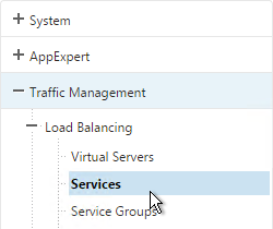
Navigation
- Lights Out Module (LOM)
- SDX IP Configuration
- Management Service Firmware – Upgrade to 11.0 build 55
- SDX Software Bundle Upgrade – Upgrade beyond 11.0 build 55
- Management Service NTP
- Licensing
- Management Service Alerting
- Management Service nsroot Password and AAA
- SSL Certificate and Encryption
- SDX/XenServer LACP Channels
- VPX Instances:
- Management Service Monitoring
- Management Service Backup
LOM IP Configuration
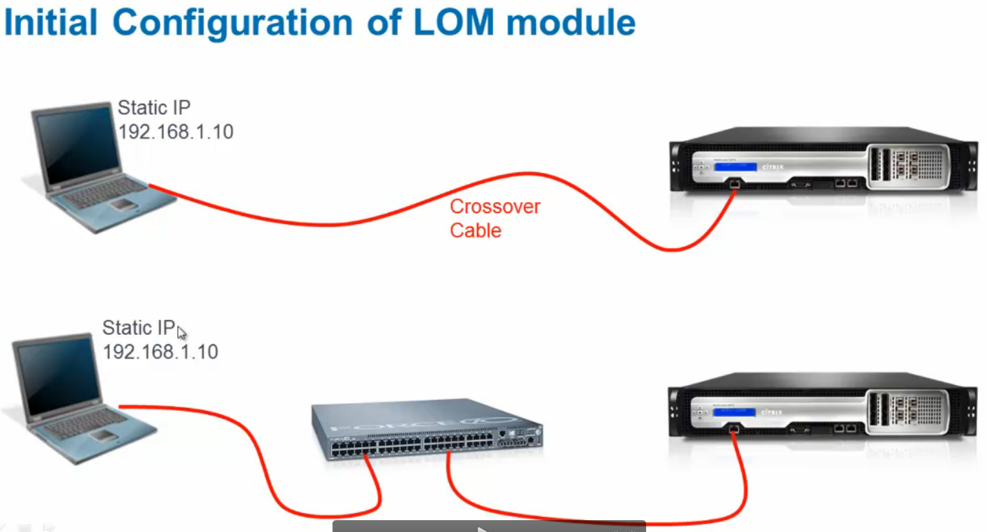
There are two ways to set the IP address of the Lights Out Module (LOM):
- Crossover Ethernet cable from a laptop with an IP address in the 192.168.1.0 network.
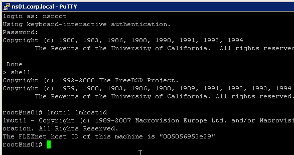
- ipmitool from the NetScaler SDX XenServer command line
Ipmitool Method:
- On NetScaler SDX appliance, SSH to the XenServer IP address (this is not the Service VM IP). On NetScaler MPX appliance, SSH to the NetScaler NSIP.
- Default XenServer credentials are root/nsroot. Default MPX credentials are nsroot/nsroot.
- If MPX, run shell. XenServer is already in the shell.
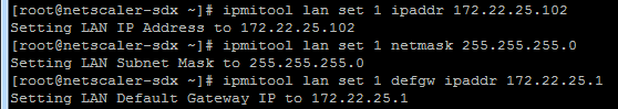
- Run the following:
ipmitool lan set 1 ipaddr x.x.x.x
ipmitool lan set 1 netmask 255.255.255.0
ipmitool lan set 1 defgw ipaddr x.x.x.x
- You should now be able to connect to the LOM using a browser.
Laptop method:
- Configure a laptop with static IP address 192.168.1.10 and connect it to the Lights Out Module port.
- In a Web browser, type the IP address of the LOM port. For initial configuration, type the port’s default address: http://192.168.1.3
- In the User Name and Password boxes, type the administrator credentials. The default username and password are nsroot/nsroot.
- In the Menu bar, click Configuration and then click Network.
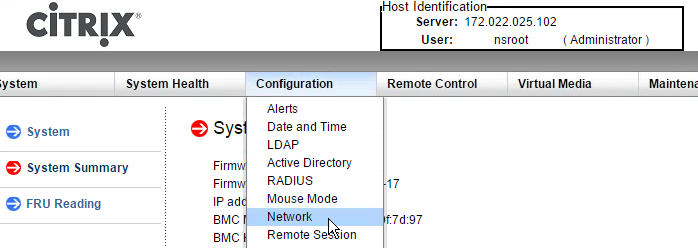
- Under Options, click Network and type values for the following parameters:
- IP Address—The IP address of the LOM port.
- Subnet Mask—The mask used to define the subnet of the LOM port.
- Default Gateway—The IP address of the router that connects the appliance to the network.
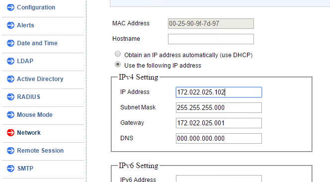
- Click Save.
- Disconnect the laptop and instead connect a cable from a switch to the Lights Out Module.
LOM Firmware Upgrade
The LOM firmware at https://www.citrix.com/downloads/netscaler-adc/components/lom-firmware-upgrade differs depending on the hardware platform. The LOM firmware for the 8000 series is different than the 11000 series. Do not mix them up.
Note: the SDX Update Bundle does not include LOM firmware update so you must update it separately.
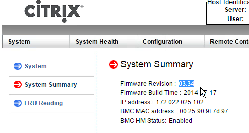
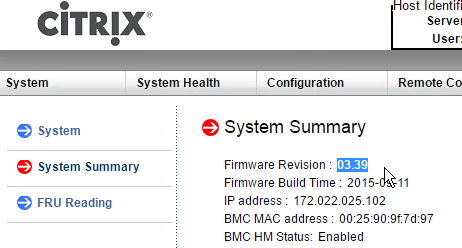
- Determine which firmware level you are currently running. You can point your browser to the LOM and login to the see the firmware level. Or you can run ipmitool mc info from the XenServer shell.
- If your LOM firmware is older than 3.0.2, follow the instructions at http://support.citrix.com/article/CTX137970 to upgrade the firmware.
- If your LOM firmware is version 3.02 or later, follow the instructions at http://support.citrix.com/article/CTX140270 to upgrade the firmware. This procedure is shown below.
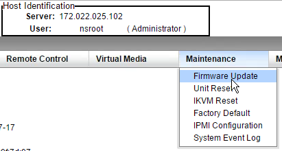
- Now that the firmware is version 3.0.2 or later, you can upgrade to 3.39. Click the Maintenance menu and then click Firmware Update.
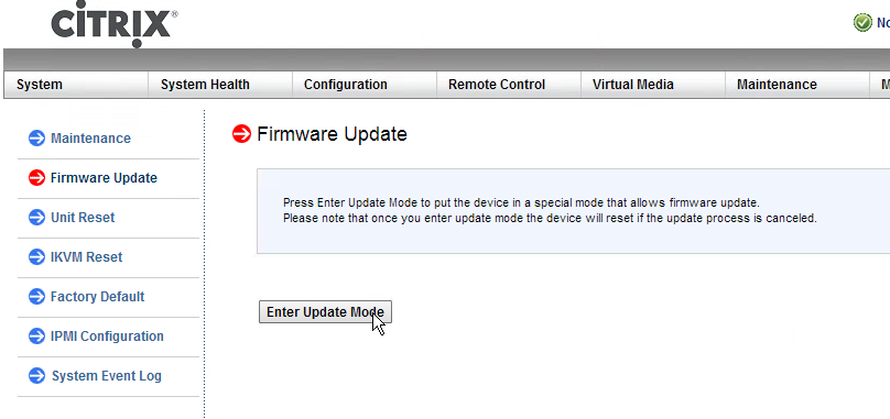
- On the right, click Enter Update Mode.
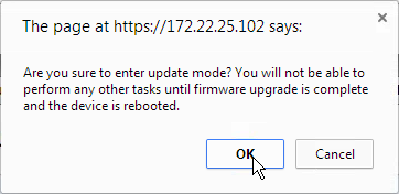
- Click OK when prompted to enter update mode.
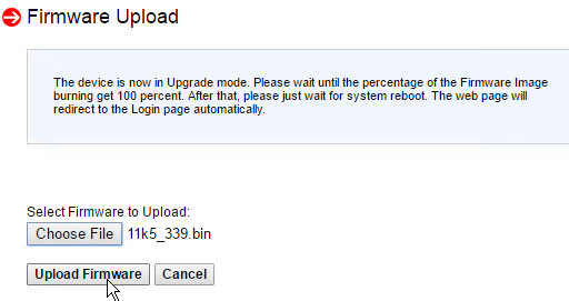
- Click Choose File and browse to the extracted bin file.
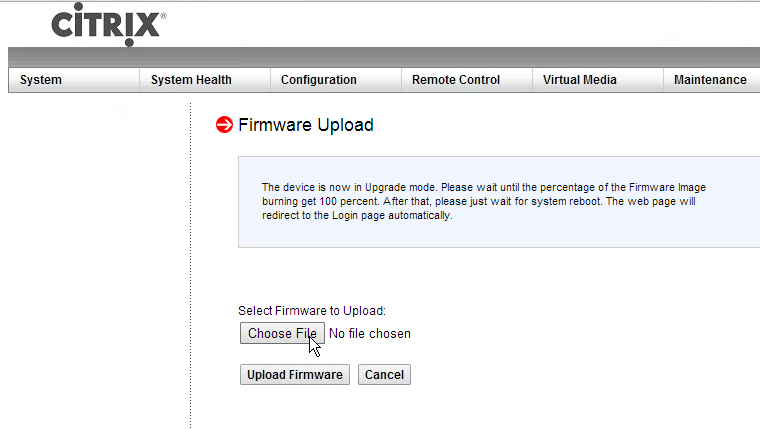
- After the file is uploaded, click Upload Firmware.
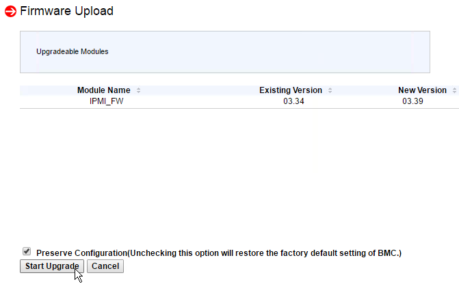
- Click Start Upgrade.
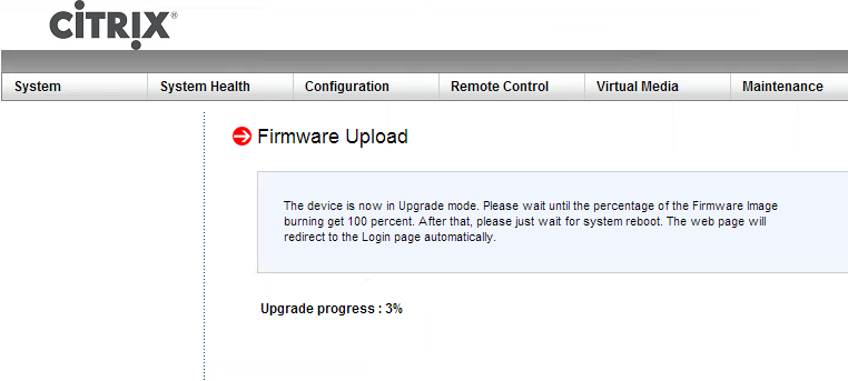
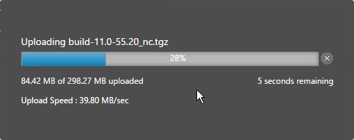
- The Upgrade progress will be displayed.
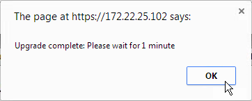
- After upgrade is complete, click OK to acknowledge the 1 minute message.
- The LOM will reboot.
- After the reboot, login and notice that the LOM firmware is now 3.39.
SDX IP Configuration
Default IP for Management Service is 192.168.100.1/16 bound to interface 0/1. Use laptop with crossover cable to reconfigure. Point browser to http://192.168.100.1. Default login is nsroot/nsroot.
Default IP for XenServer is 192.168.100.2/16. Default login is root/nsroot. Note: XenServer IP and Management Service IP must be on the same subnet.
There should be no need to connect to XenServer directly. Instead, all XenServer configuration (e.g. create new VM) is performed through the Management Service (SVM). To change the XenServer IP, make the change through the Management Service as detailed below:
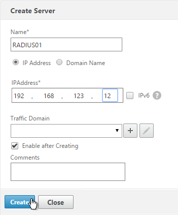
- Point a browser to http://192.168.100.1 and login as nsroot/nsroot.
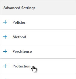
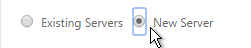
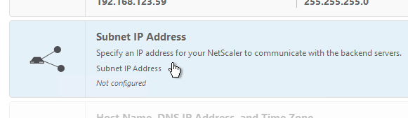
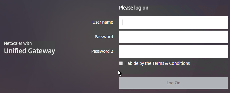
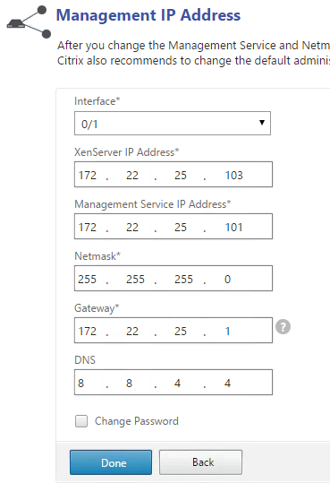
- When you first login to the SDX Management Service, the Welcome! Wizard appears. Click Management Network.
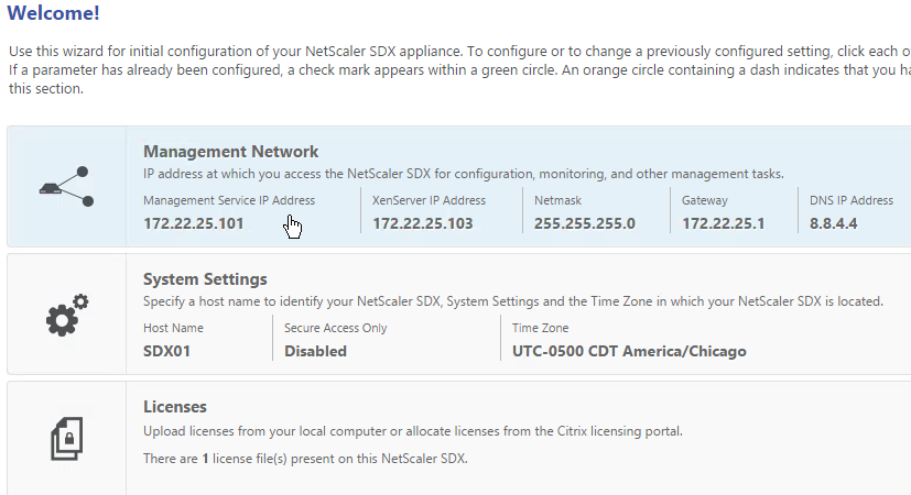
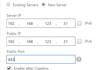
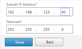
- Configure the IP addresses. Management Service IP Address and XenServer IP Address must be different but on the same subnet.
- You can change the password at this time or later. Click Done.
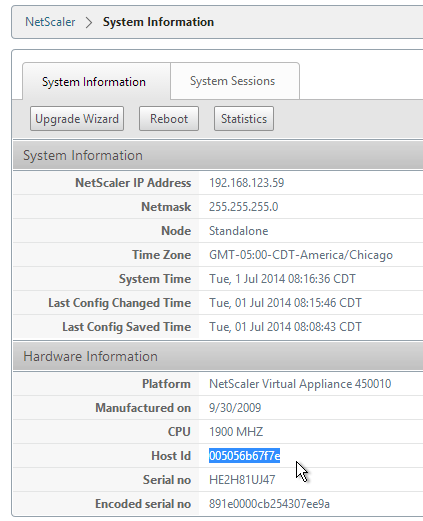
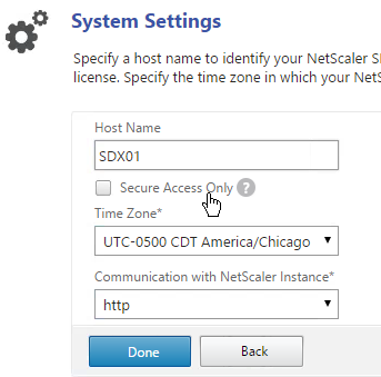
- Click the System Settings box.
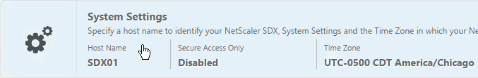
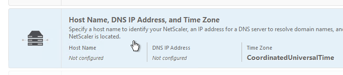
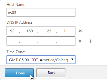
- Enter a Host Name.
- Select the time zone and click Continue.
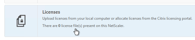
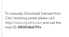
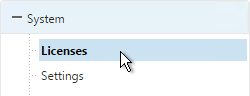
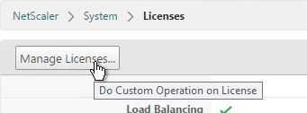
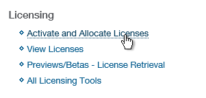
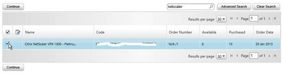
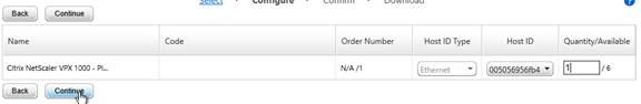
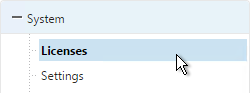
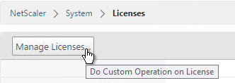
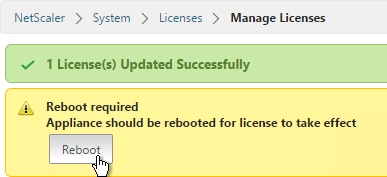
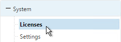
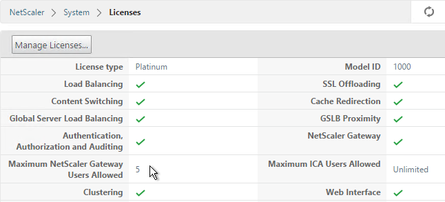
- Click the Licenses box.
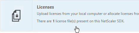
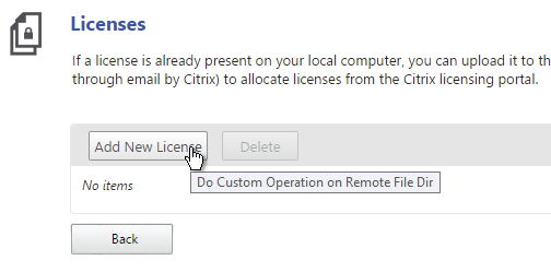
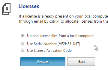
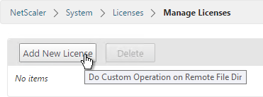
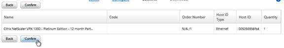
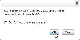
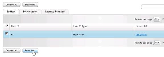
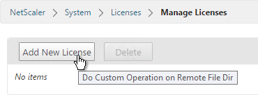
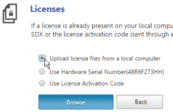
- Click Add New License.
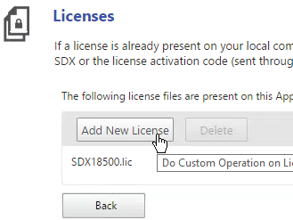
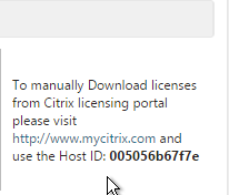
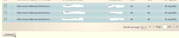
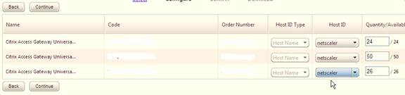
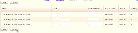
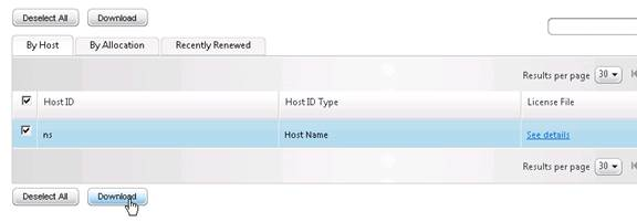
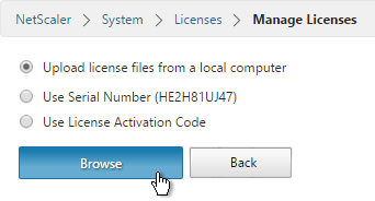
- In the Manage Licenses section, allocate licenses normally.
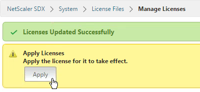
- Then click Continue.

Another way to login to the Management Service virtual machine is through the serial port. This is actually the XenServer Dom0 console. Once logged in to XenServer, run ssh 169.254.0.10 to access the Management Service virtual machine. Then follow instructions at http://support.citrix.com/article/CTX130496 to change the IP.
The console of the Management Service virtual machine can be reached by running the following command in the XenServer Dom0 shell (SSH or console):
xe vm-list params=name-label,dom-id name-label="Management Service VM"
Then run /usr/lib/xen/bin/xenconsole <dom-id>
Or if 11.0 build 64 or newer, run /usr/lib64/xen/bin/xenconsole <dom-id>
Management Service Firmware – Upgrade to 11.0
NetScaler SDX 11.0 and newer now bundle all updates in a single package. To take advantage of this improved installation experience, you must first upgrade the Service VM to 11.0. Once it’s 11.0 you no longer need to upgrade the Service VM separately from the rest of the appliance.
- If your SDX SVM (Management Service) is running 10.5 build 57 or newer then you can skip this section and proceed with installing the SDX Bundle.
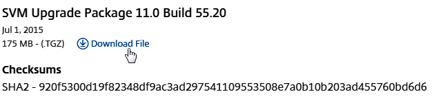
- NetScaler SDX 11.0 build 55 contains a separate installer for just the Management Service (SVM Upgrade Package). The newer builds of NetScaler SDX 11.0 don’t seem to have a separate SVM Upgrade Package so you’ll need to upgrade SVM to 11.0 build 55 first. Then use the Software Bundle method to upgrade beyond build 55 as detailed in the next section.
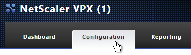
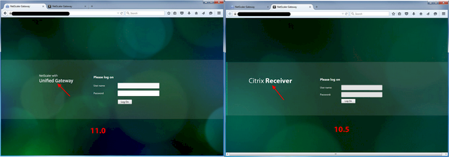
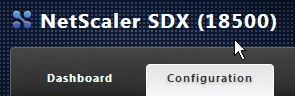
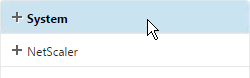
- If the webpage says NetScaler SDX on top then you are connected to the Service VM.
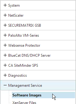
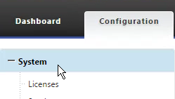
- Switch to the Configuration tab.
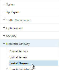
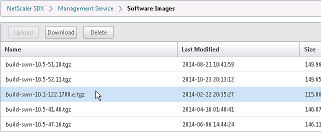
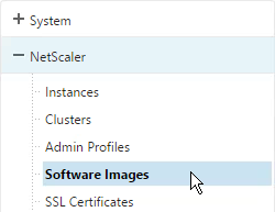
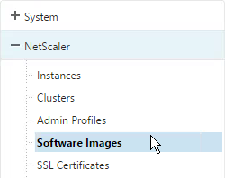
- In the navigation pane, expand Management Service, and then click Software Images.
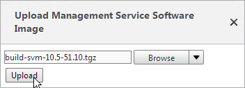
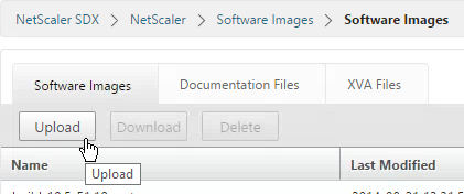
- In the right pane, click Upload.

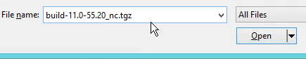
- In the Upload Management Service Software Image dialog box, click Browse, navigate to the folder that contains the build-svm file, and then double-click the build file.
- Click Upload.
To upgrade the Management Service:
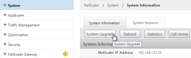
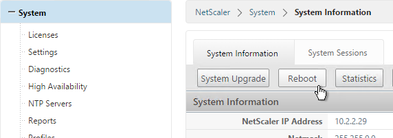
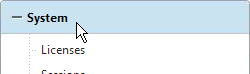
- In the navigation pane, click System.
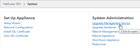
- In the System pane, under System Administration, click Upgrade Management Service.
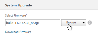
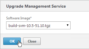
- In the Upgrade Management Service dialog box, in Build File, select the file of the build to which you want to upgrade the Management Service.
- If you see a Documentation File field, ignore it.
- Click OK.
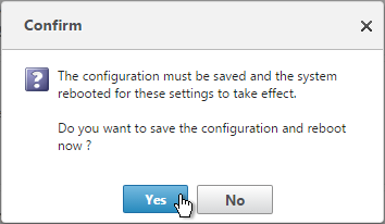
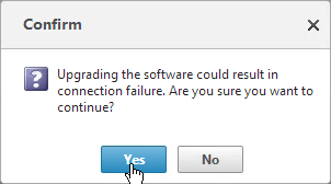
- Click Yes if asked to continue.
- If desired, go back to the Software Images node and delete older firmware files.
SDX Platform Software Bundle
Starting with SDX 11.0, all updates are bundled together and installed at once.
- Make sure your Management Service (SVM) is running SDX 11.0 or newer. If not, see the separate SVM upgrade procedure in the previous section.
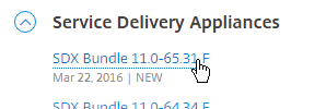
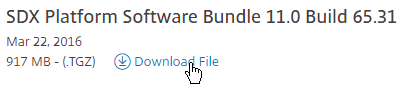
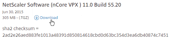
- Download the latest SDX Platform Software bundle from Downloads > NetScaler ADC > Service Delivery Appliances.
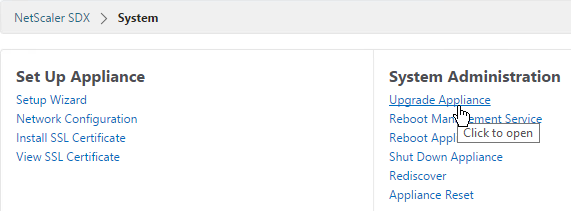
- Login to the SDX Management Service, go to Configuration > System.
- On the right, in the right column, click Upgrade Appliance.
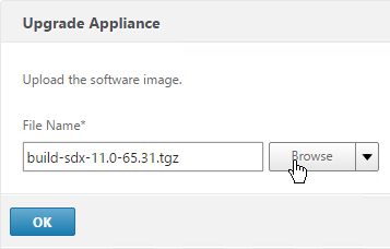
- Browse to the build-sdx-11.0.tgz software bundle and click OK.
- It should show you the estimated installation time. Check boxes next to the instances that need configs saved. Click Upgrade.
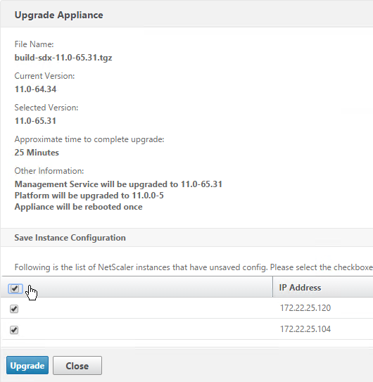
- Click Yes to continue with the upgrade.

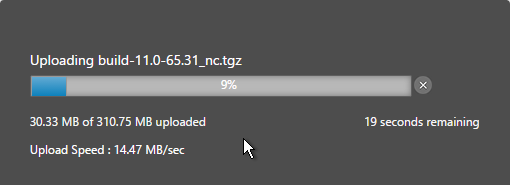
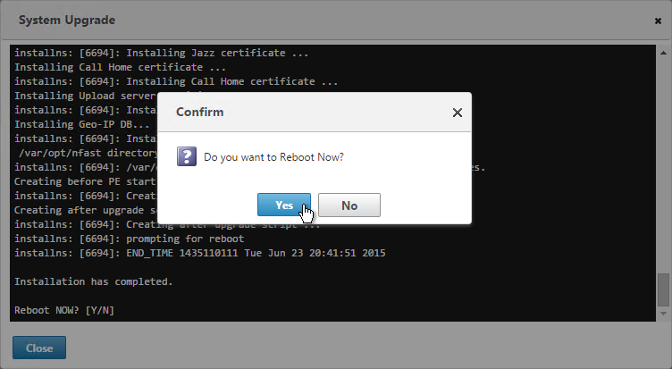
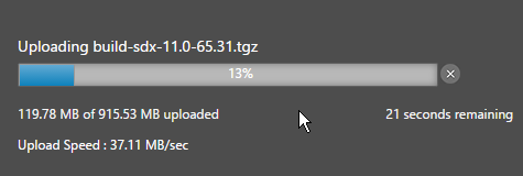
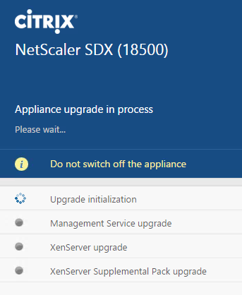
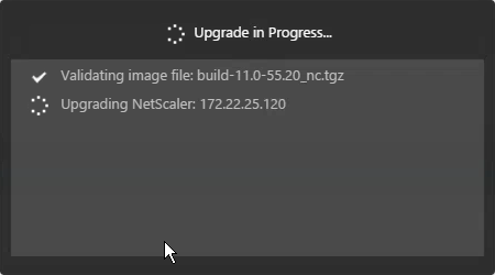
- The Management Service displays installation progress.
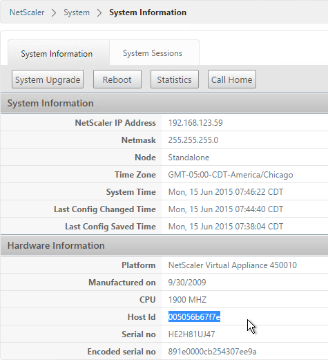
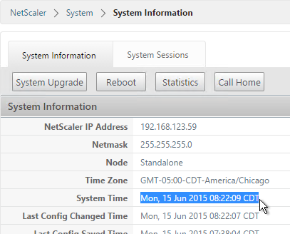
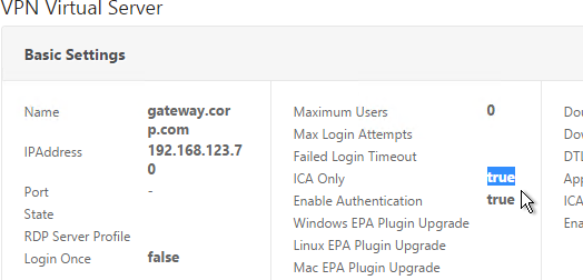
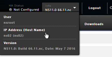
Once the upgrade is complete, click Login. 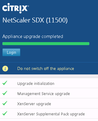
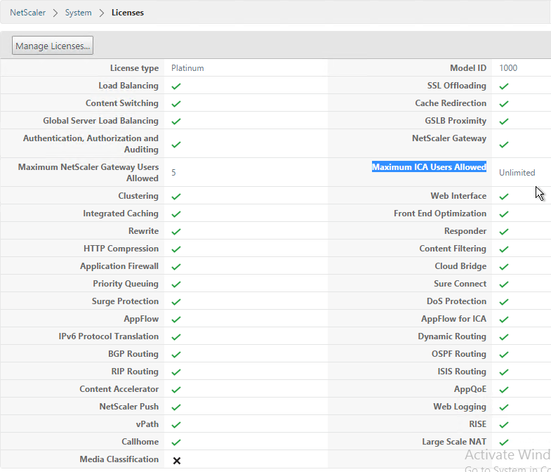
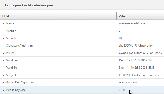
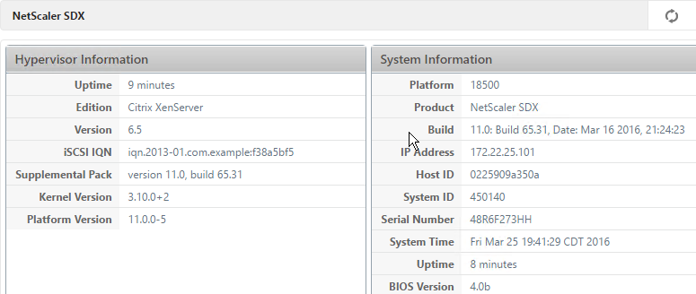
- The Information page will be displayed showing the version of XenServer, Management Service (Build), etc.
Management Service NTP
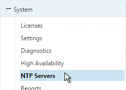
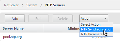
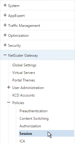
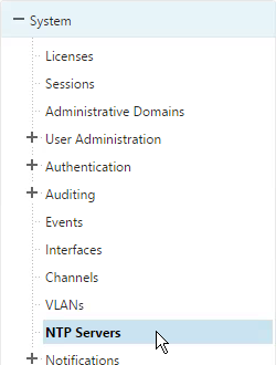
- On the Configuration tab, in the navigation pane, expand System, and then click NTP Servers.
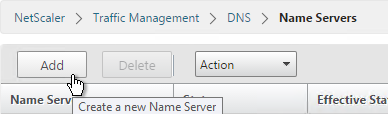
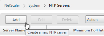
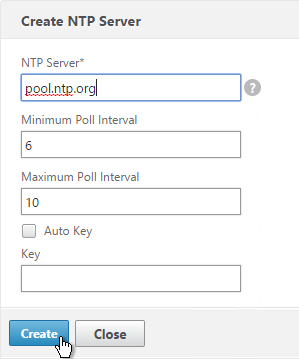
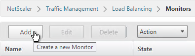
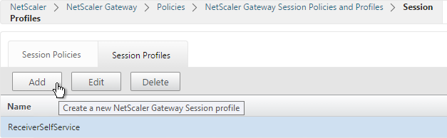
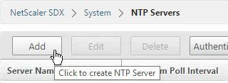
- To add a new NTP server, in the right pane, click Add.
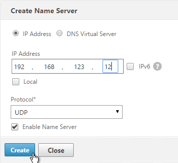
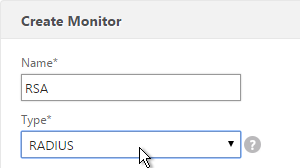
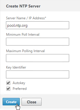
- In the Create NTP Server dialog box enter the NTP server name (e.g. pool.ntp.org) and click Create.
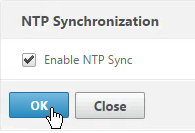
- In the right pane click NTP Synchronization.
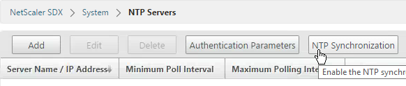
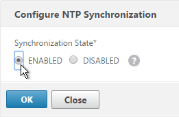
- In the NTP Synchronization dialog box, select Enable NTP Sync. Click OK.
Management Service Alerting
Syslog
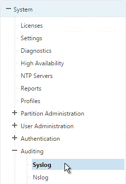
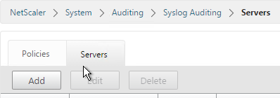
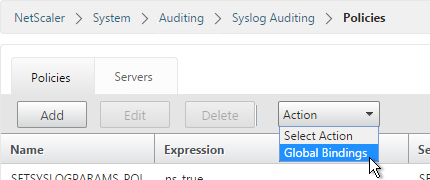
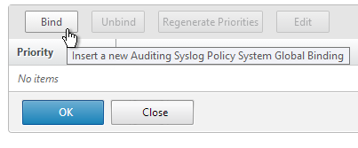
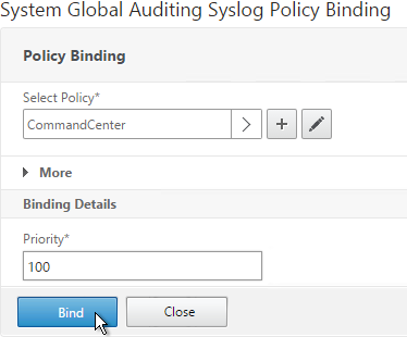
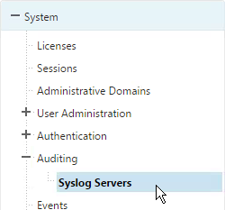
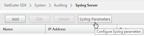
- On the Configuration tab, expand System > Auditing and click Syslog Servers.
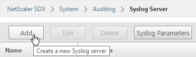
- In the right pane click the Add button.
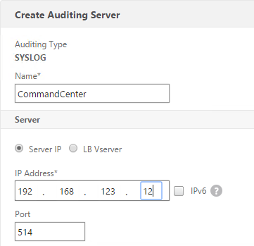
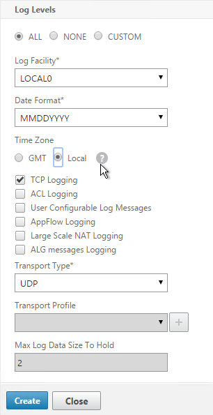
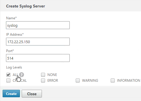
- Enter a name for the server.
- Enter the IP address of the Syslog server.
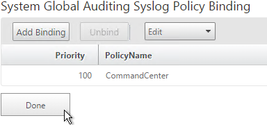
- Select log levels and click Create.
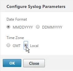
- On the right is Syslog Parameters.
- You can configure the Date Format and Time Zone. Click OK.
Mail Notification
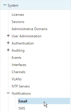
- On the Configuration tab, expand System > Notifications and click Email.
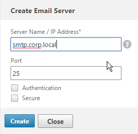
- In the right pane, on the Email Servers tab, click Add.
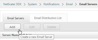
- Enter the DNS name of the mail server and click Create.
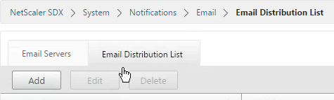
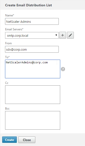
- In the right pane, switch to the Email Distribution List tab and click Add.
- Enter a name for the mail profile.
- Enter the destination email address and click Create.
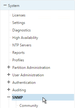
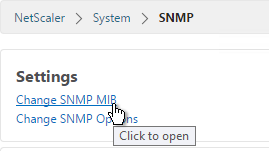
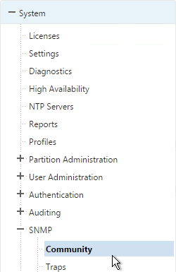
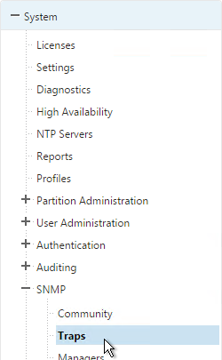
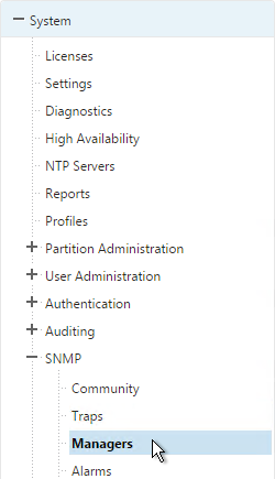
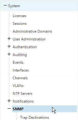
System SNMP
- Go to System > SNMP.
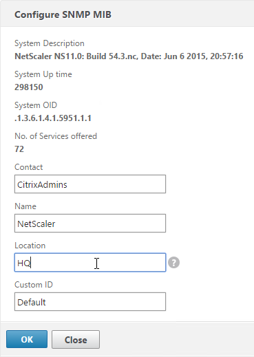
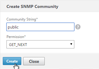
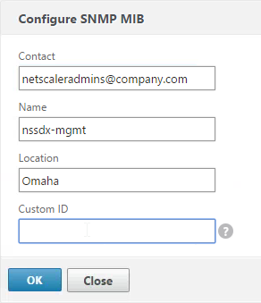
- On the right, click Configure SNMP MIB.
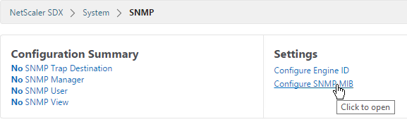
- Enter information as desired and click OK. Your SNMP management software will read this information.
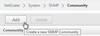
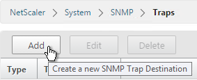
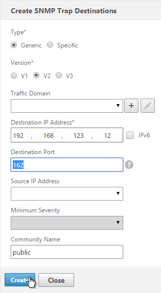
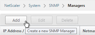
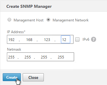
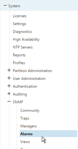
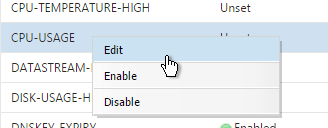
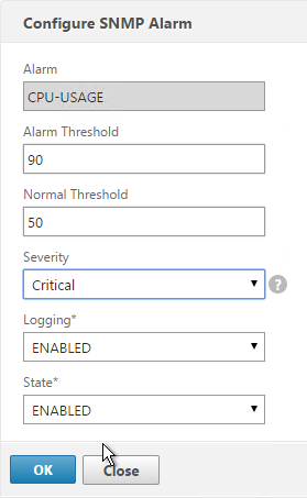
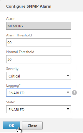
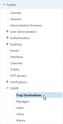
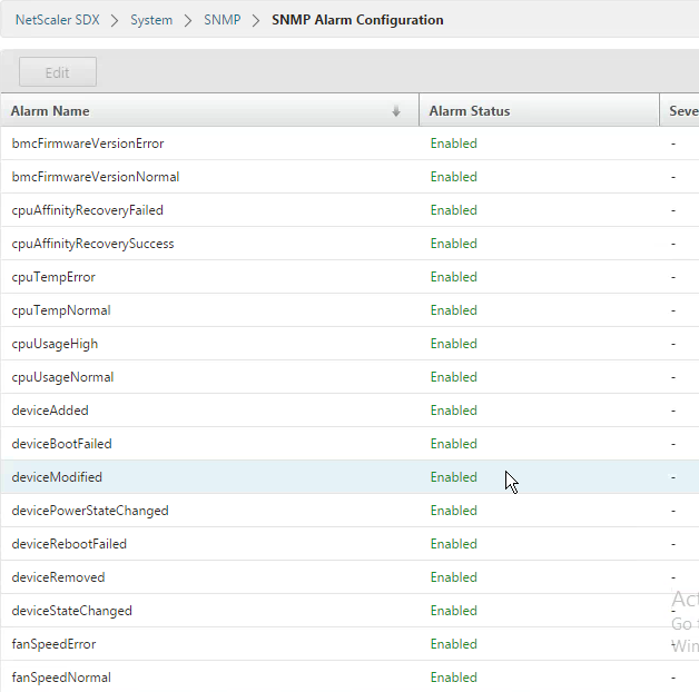
- Under the SNMP node, configure normal SNMP including: Trap Destinations, Managers, Alarms, etc.
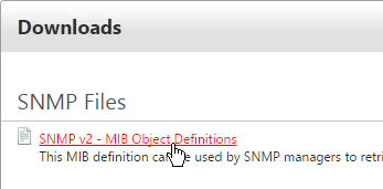
- MIBs can be downloaded from the Downloads tab.
Instance SNMP
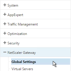
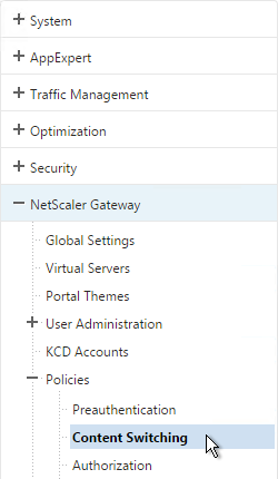
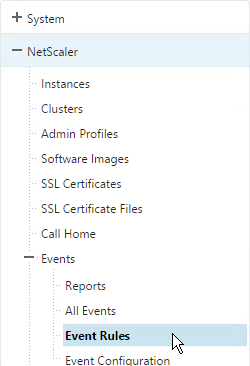
- The instances will send SNMP traps to the Service VM. To get alerted for these traps, in the Configuration page, in the navigation pane, expand NetScaler, expand Events, and click Event Rules.
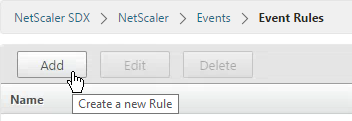
- On the right, click Add.
- Give the rule a name.
- Select the Major and Critical severities and move them to the right. Scroll down.
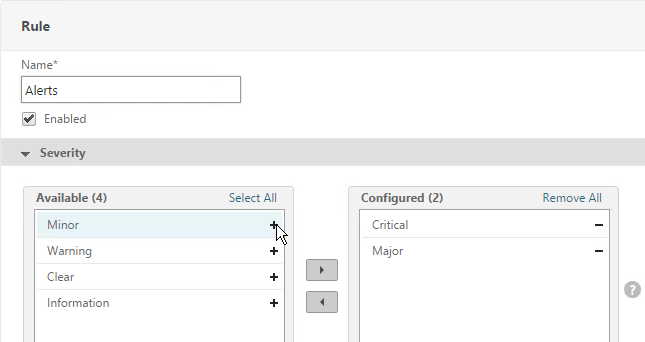
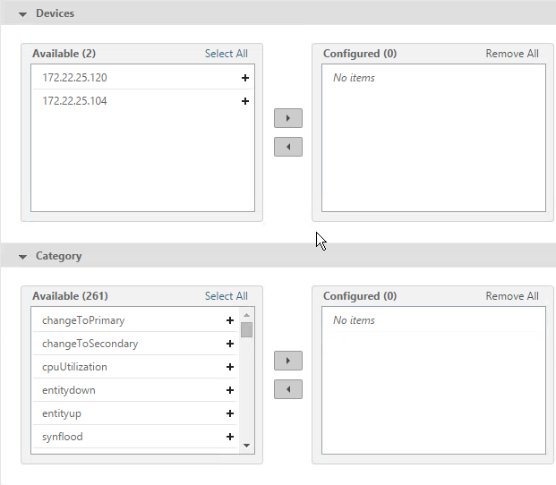
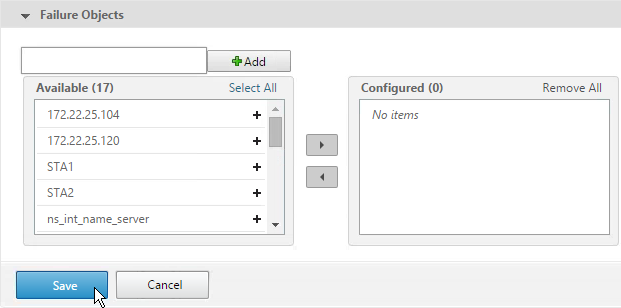
- For the other sections, if you don’t configure anything then you will receive alerts for all of the devices, categories, and failure objects. If you configure any of them then only the configured entities will be alerted. Scroll down.
- Click Save.
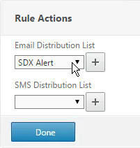
- Select an Email Distribution List and click Done.
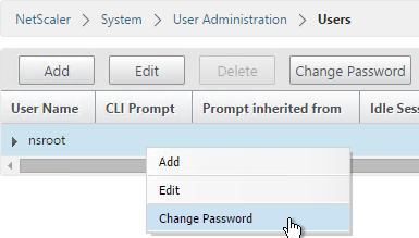
Management Service nsroot Password and AAA
To change the password of the default user account
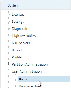
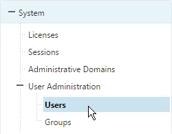
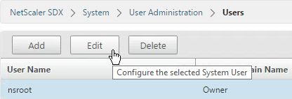
- On the Configuration tab, in the navigation pane, expand System, and then click Users.
- In the Users pane, click the default user account, and then click Edit.
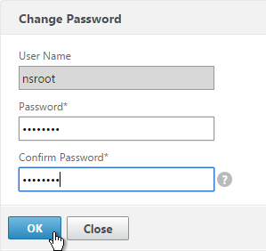
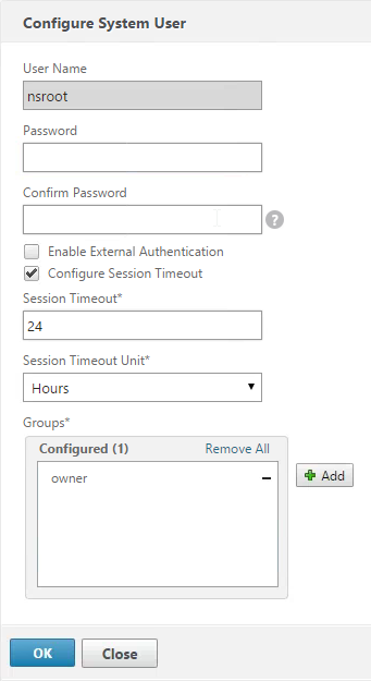
- In the Configure System User dialog box, in Password and Confirm Password, enter the password of your choice. Click OK.
To create a user account
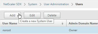
- In the navigation pane, expand System, and then click Users. The Users pane displays a list of existing user accounts, with their permissions.
- To create a user account, click Add.
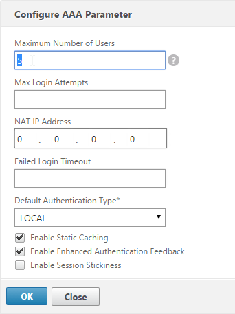
- In the Create System User or Modify System User dialog box, set the following parameters:
- Name*—The user name of the account. The following characters are allowed in the name: letters a through z and A through Z, numbers 0 through 9, period (.), space, and underscore (_). Maximum length: 128. You cannot change the name.
- Password*—The password for logging on to the appliance.
- Confirm Password*—The password.
- Session Timeout
- Groups —The user’s privileges on the appliance. Possible values:
- owner—The user can perform all administration tasks related to the Management Service.
- readonly—The user can only monitor the system and change the password of the account.
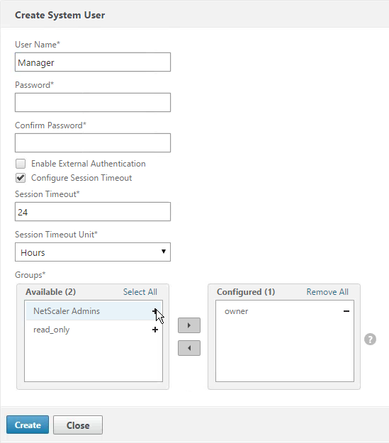
- Click Create. The user that you created is listed in the Users pane.
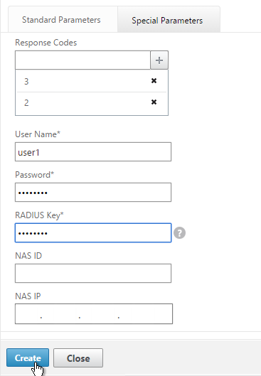
AAA Authentication
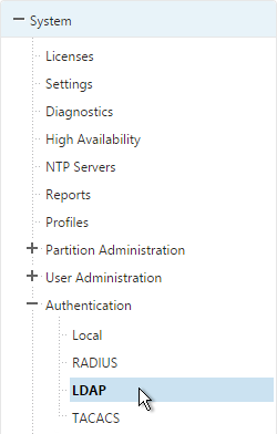
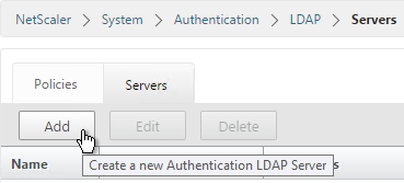
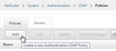
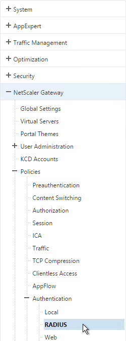
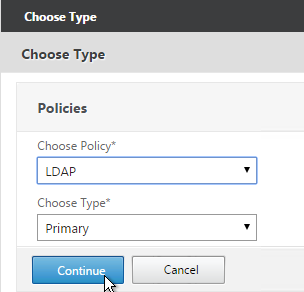
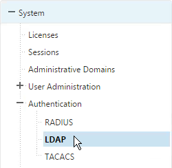
- If you would like to enable LDAP authentication for the Service VM, do that under Configuration > System > Authentication > LDAP.
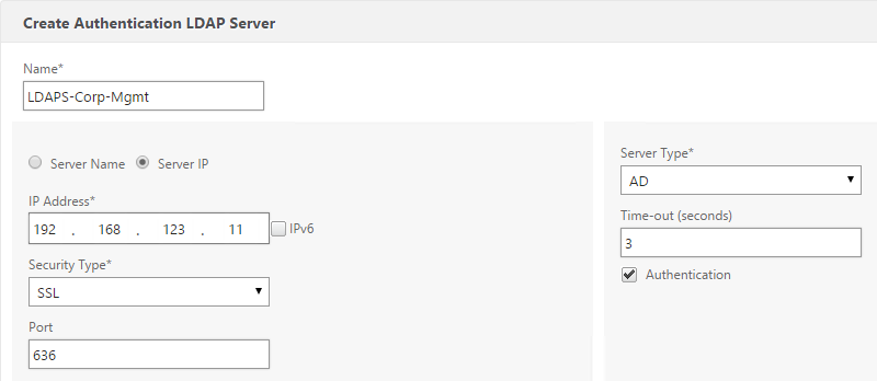
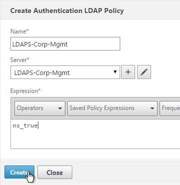
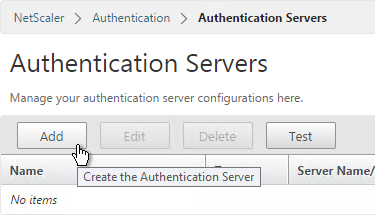
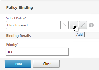
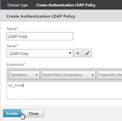
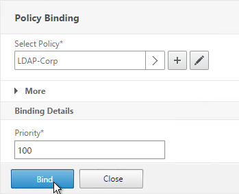
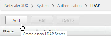
- In the right pane, click Add.
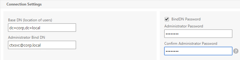
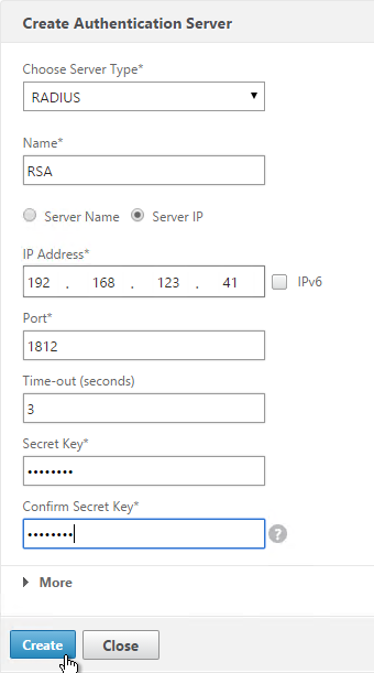
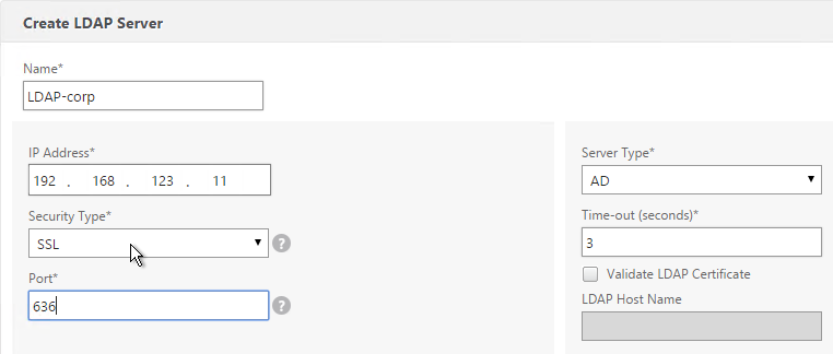
- This is configured identically to NetScaler. Enter a Load Balancing VIP for LDAP. Change the Security Type to SSL and Port to 636. Scroll down.
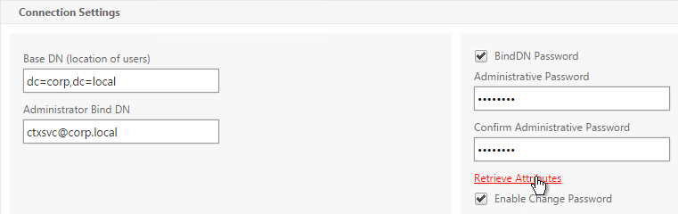
- Enter the Base DN in LDAP format.
- Enter the bind account.
- Check the box for Enable Change Password.
- Click Retrieve Attributes and scroll down.
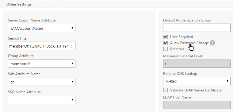
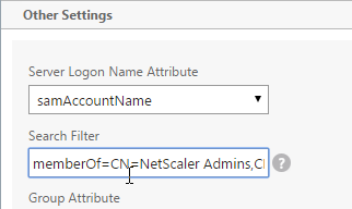
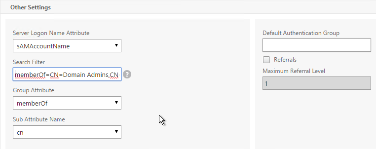
- For Server Logon Attribute select sAMAccountName.
- For Group Attribute select memberOf.
- For Sub Attribute Name select cn.
- To prevent unauthorized users from logging in, configure a Search Filter. Scroll down.
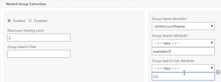
- If desired configure Nested Group Extraction
- Click Create.
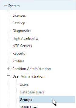
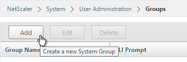
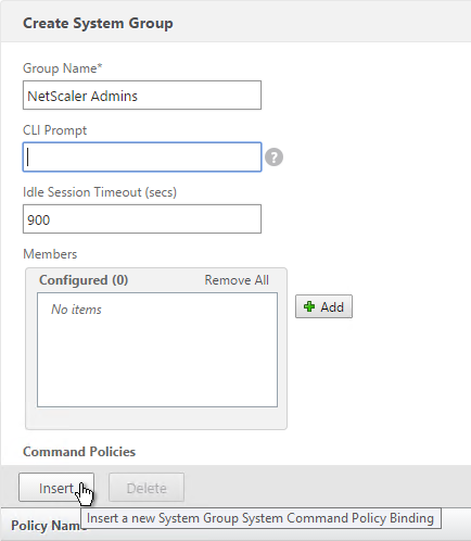
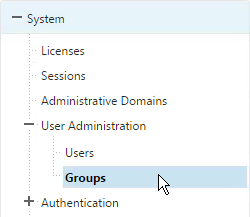
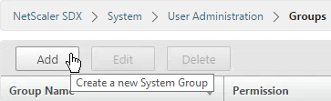
- Expand System, expand User Administration and click Groups.
- Click Add.
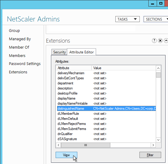
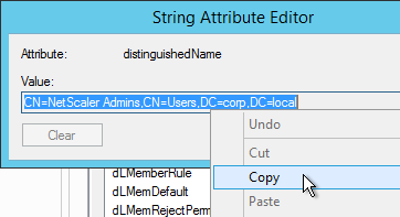
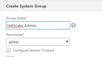
- Enter the case sensitive name of the Active Directory group.
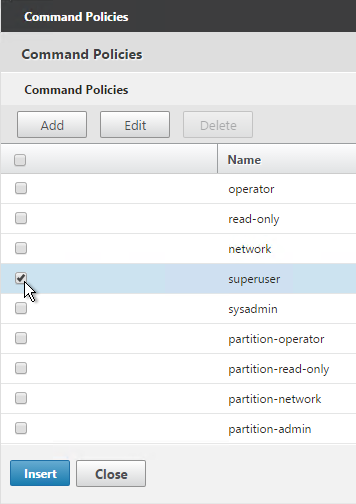
- Select the admin permission.
- Configure the Session Timeout. Click Create.
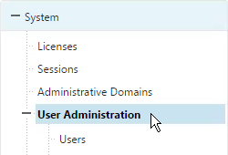
- On the left, under System, click User Administration.
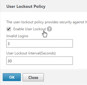
- On the right click User Lockout Configuration.
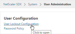
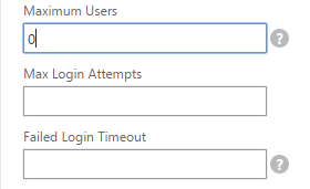
- If desired, check the box next to Enable User Lockout and configure the maximum logon attempts. Click OK.
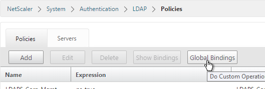
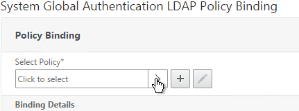
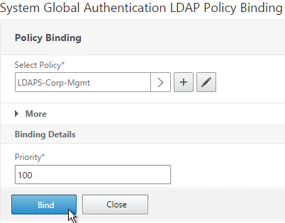
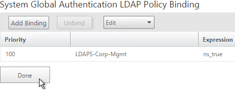
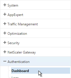
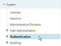
- On the left, under System, click Authentication.
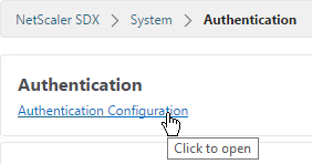
- On the right, click Authentication Configuration.
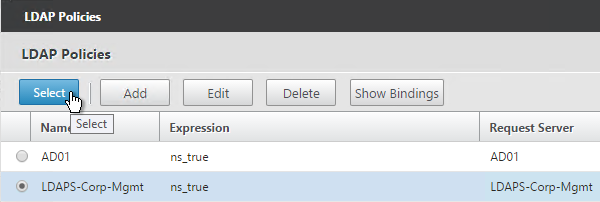
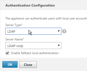
- Change the Server Type to LDAP.
- Select the LDAP server you created and click OK.
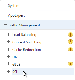
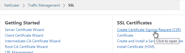
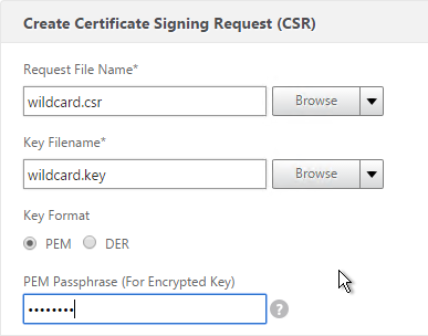
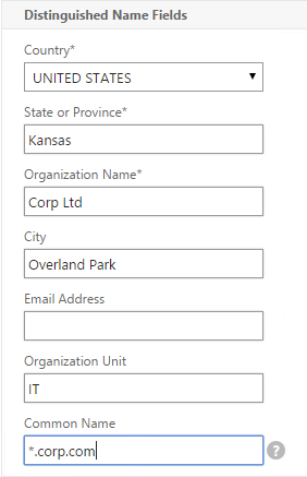
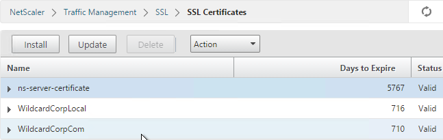
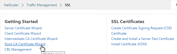
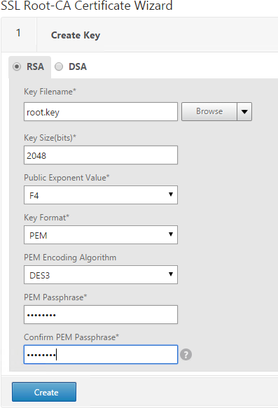
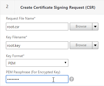
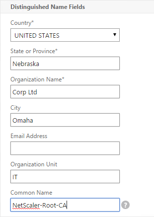
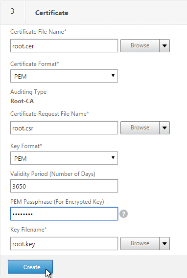
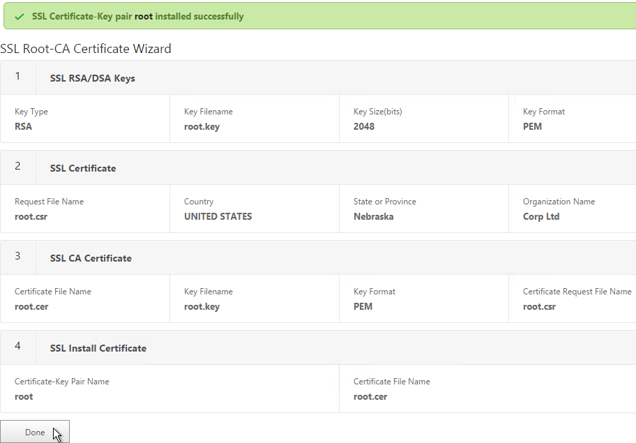
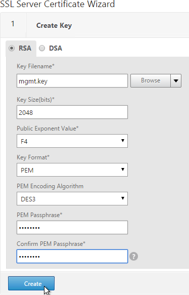
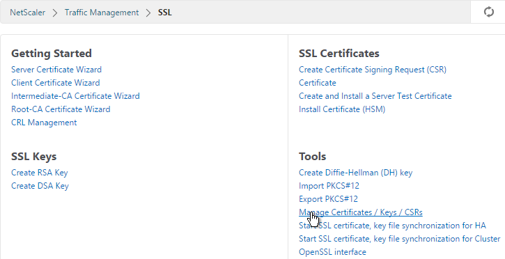
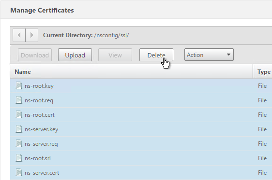
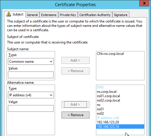
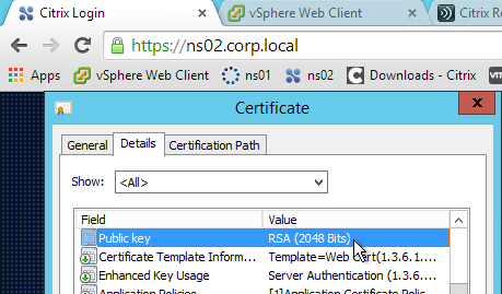
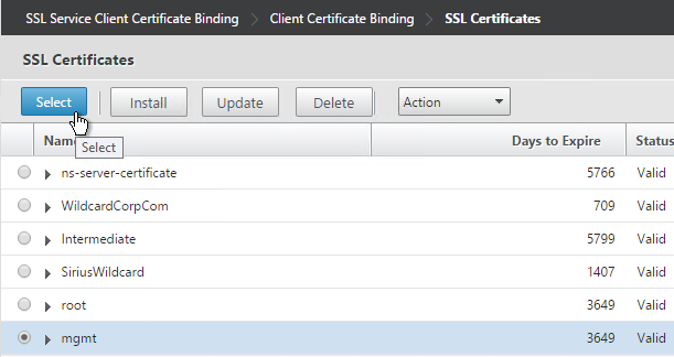
SSL Certificate and Encryption
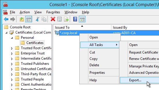
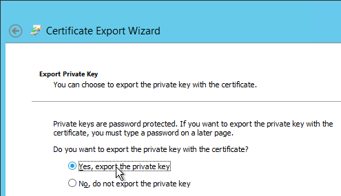
Replace SDX Management Service Certificate
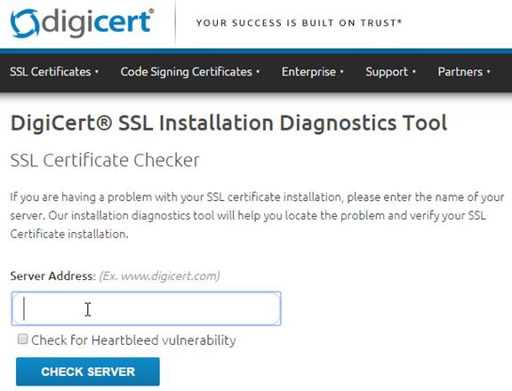
Before enabling secure access to the Management Service web console, you probably want to replace the Management Service certificate.
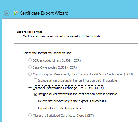
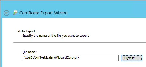
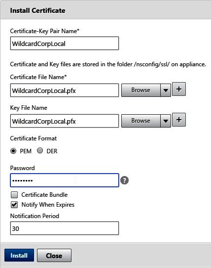
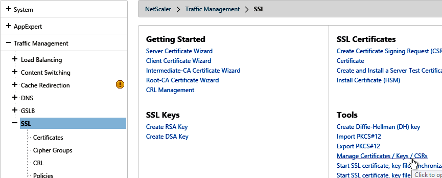
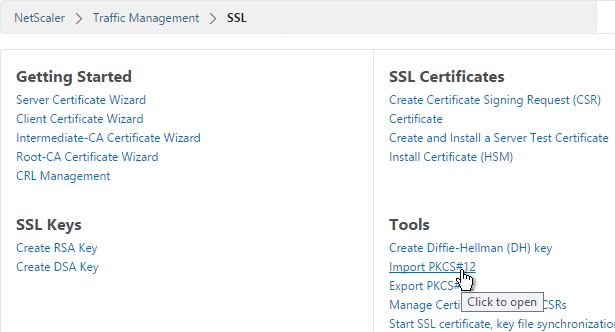
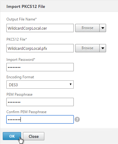
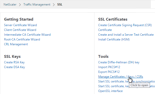
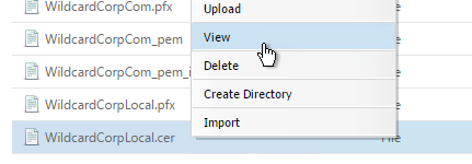
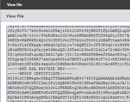
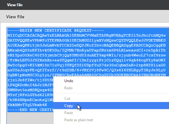
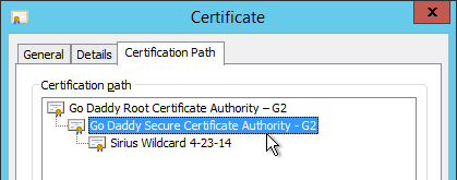
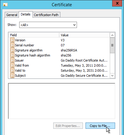
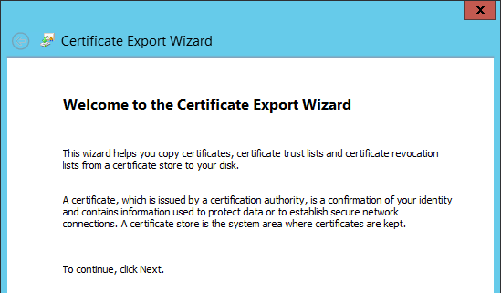
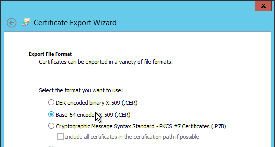
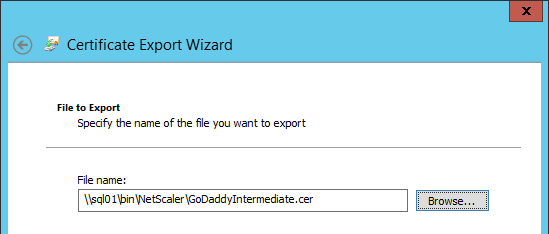
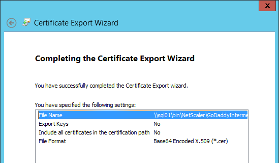
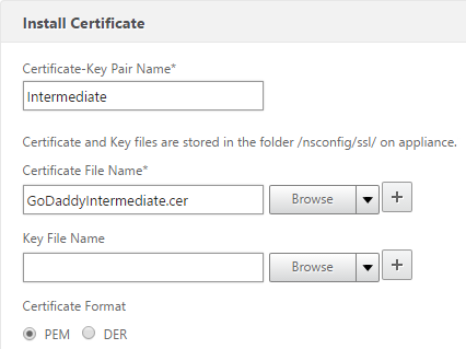
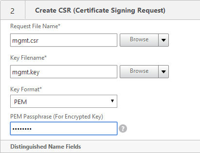
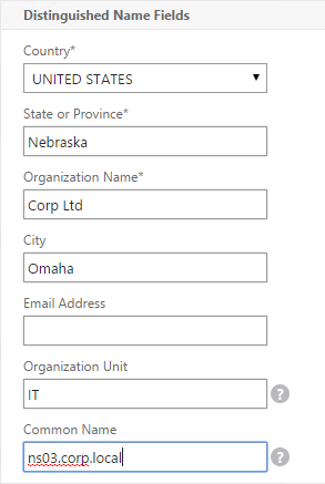
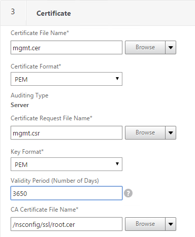
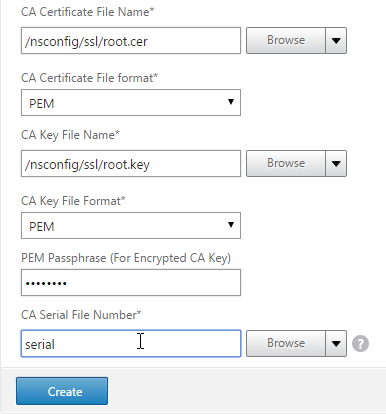
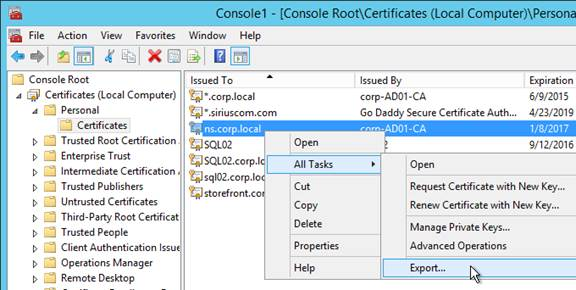
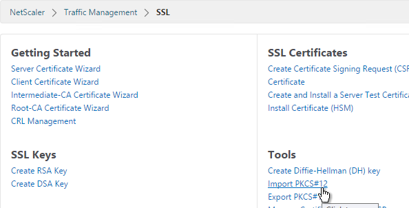
- PEM format: The certificate must be in PEM format. The Management Service does not provide any mechanism for converting a PFX file to PEM. You can convert from PFX to PEM by using the Import PKCS#12 task in a NetScaler instance.
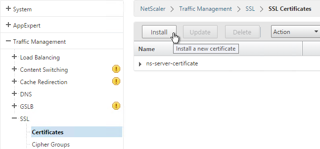
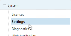
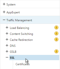
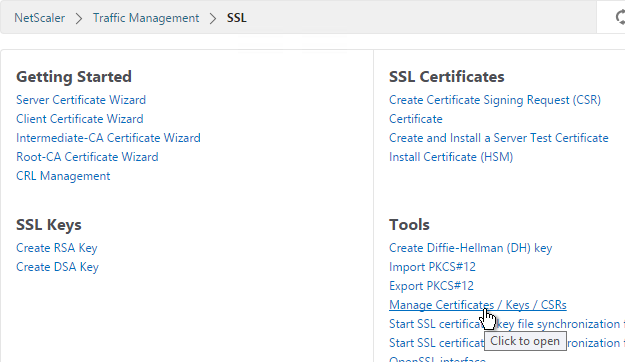
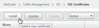
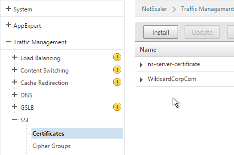
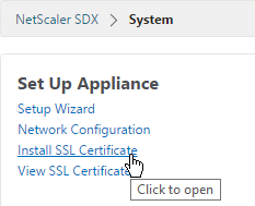
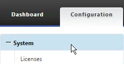
- On the left, click System.
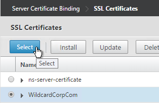
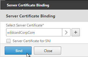
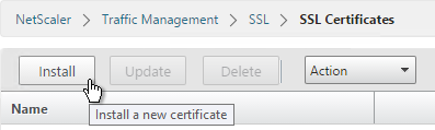
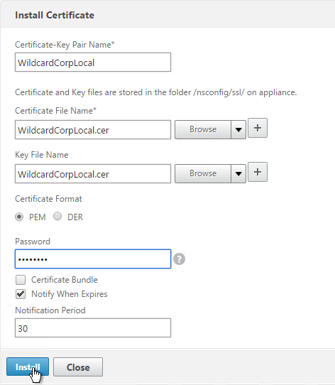
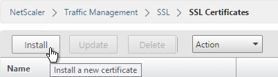
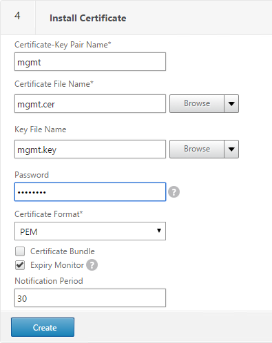
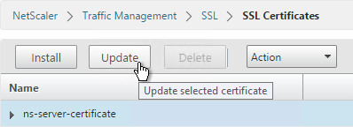
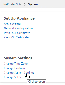
- On the right, click Install SSL Certificate.
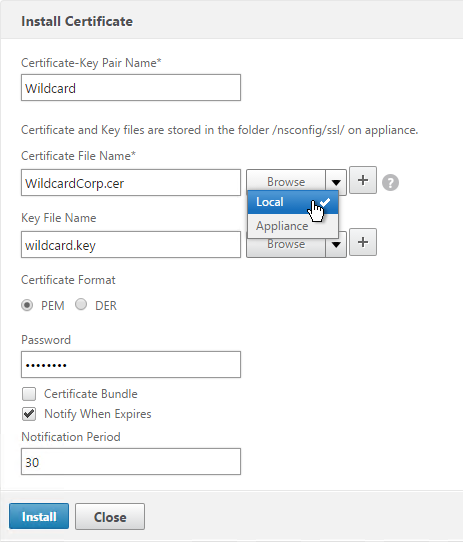
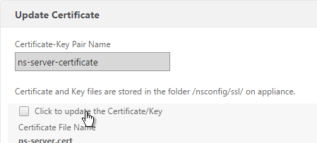
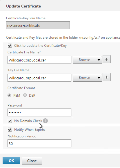
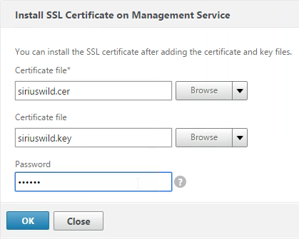
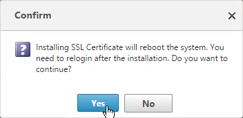
- Select the certificate and key files in PEM format. If the key file is encrypted, enter the password. Then click OK. The Management Service will restart so there will be an interruption.
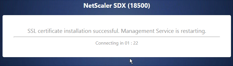
- After the Management Service restarts, connect to it using HTTPS. You can’t make this change if you are connected using HTTP.
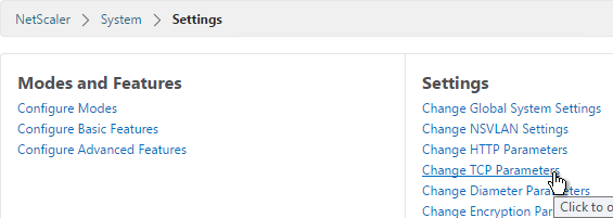
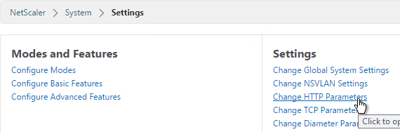
- On the Configuration tab, click System.
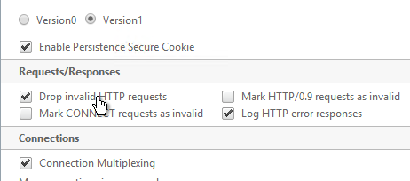
- On the right, click Change System Settings.
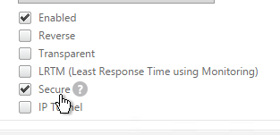
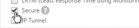
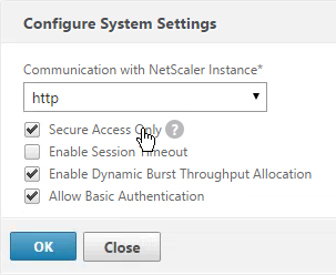
- Check the box next to Secure Access Only and click OK. This forces you to use HTTPS to connect to the Management Service.
SSL Encrypt Management Service to NetScaler Communication
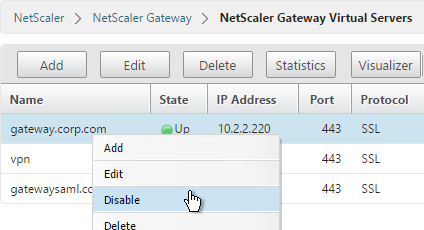
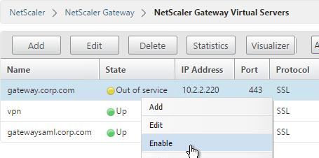
From http://support.citrix.com/article/CTX134973: Communication from the Management Service to the NetScaler VPX instances is HTTP by default. If you want to configure HTTPS access for the NetScaler VPX instances, then you have to secure the network traffic between the Management Service and NetScaler VPX instances. If you do not secure the network traffic from the Management Service configuration, then the NetScaler VPX Instance State appears as Out of Service and the Status shows Inventory from instance failed.
- Log on to the Management Service .
- On the Configuration tab, click System.
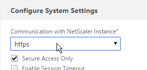
- On the right, click Change System Settings.
- Change Communication with NetScaler Instance to https, as shown in the following screen shot:
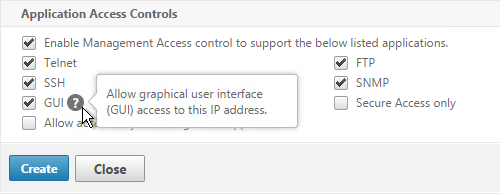
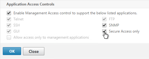
- Run the following command on the NetScaler VPX instance, to change the Management Access (-gui) to SECUREONLY:
set ns ip ipaddress -netmask netmask -arp ENABLED -icmp ENABLED -vServer DISABLED -telnet ENABLED -ftp ENABLED -gui SECUREONLY -ssh ENABLED -snmp ENABLED - mgmtAccess ENABLED -restrictAccess DISABLED -dynamicRouting ENABLED -ospf DISABLED -bgp DISABLED -rip DISABLED -hostRoute DISABLED -vrID 0
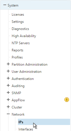
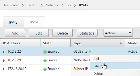
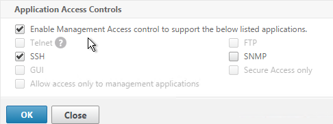
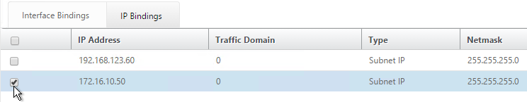
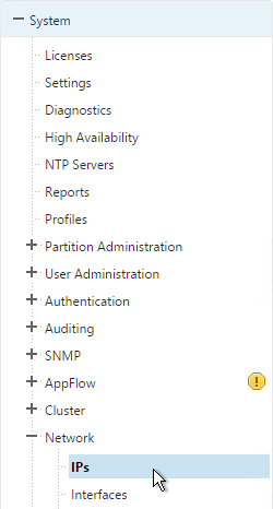
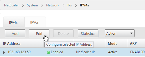
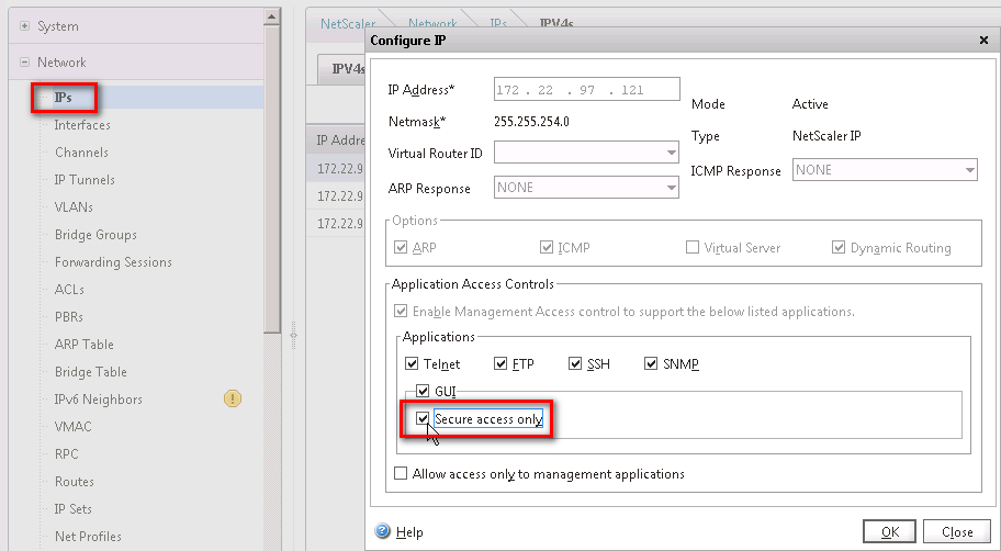
Or in the NetScaler instance management GUI go to Network > IPs, open the NSIP and then check the box next to Secure access only.
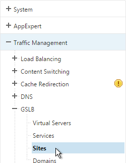
SDX/XenServer LACP Channels
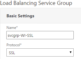
To use LACP, configure Channels in the Management Service, which creates them in XenServer. Then when provisioning an instance, connect it to the Channel.
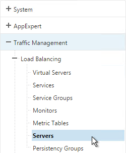
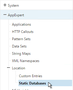
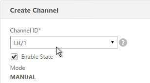
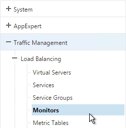
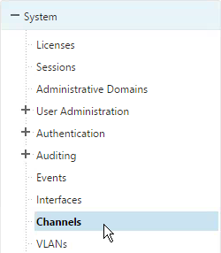
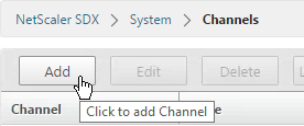
- In the Management Service, on the Configuration tab, expand System and click Channels.
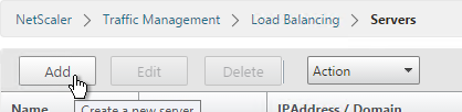
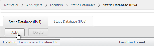
- On the right, click Add.
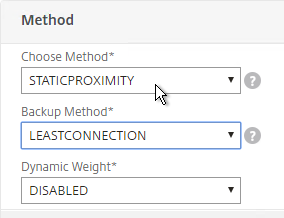
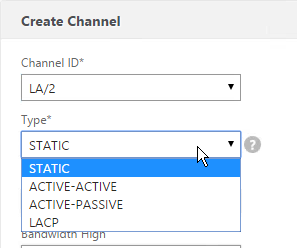
- Select a Channel ID.
- For Type, select LACP or STATIC. If using Cisco vPC then LACP is required. The other two options are for switch independent load balancing.
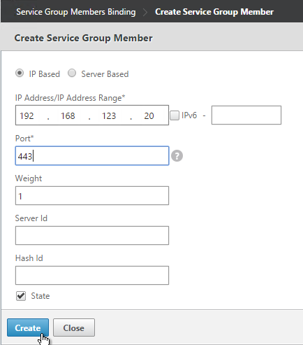
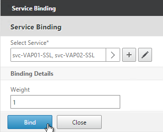
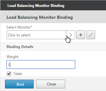
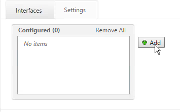
- In the Interfaces tab, click Add.
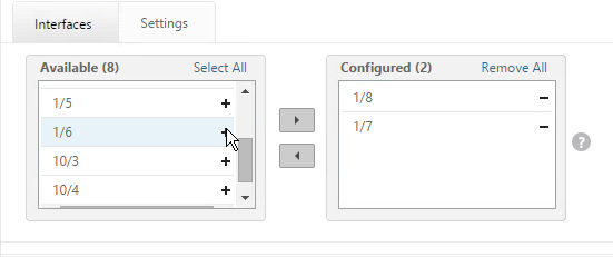
- Move the Channel Member interfaces to the right by clicking the plus icon.
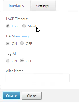
- On the Settings tab, for LACP you can select Long or Short, depending on switch configuration. Short is the default.
- Click Create when done.
- Click Yes when asked to proceed.
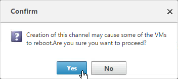
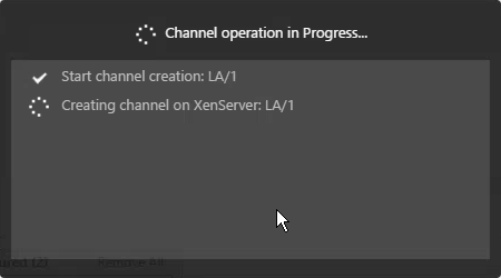
- The channel will then be created on XenServer.
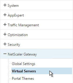
VPX Instances – Provision
To create an admin profile
Admin profiles specify the user credentials that are used by the Management Service when provisioning the NetScaler instances, and later when communicating with the instances to retrieve configuration data. The user credentials specified in an admin profile are also used by the client when logging on to the NetScaler instances through the CLI or the configuration utility.
The default admin profile for an instance specifies a user name of nsroot, and the password is also nsroot. This profile cannot be modified or deleted. However, you should override the default profile by creating a user-defined admin profile and attaching it to the instance when you provision the instance. The Management Service administrator can delete a user-defined admin profile if it is not attached to any NetScaler instance.
Important: Do not change the password directly on the NetScaler VPX instance. If you do so, the instance becomes unreachable from the Management Service. To change a password, first create a new admin profile, and then modify the NetScaler instance, selecting this profile from the Admin Profile list.
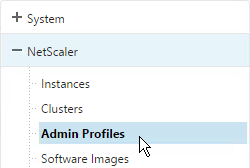
- On the Configuration tab, in the navigation pane, expand NetScaler Configuration, and then click Admin Profiles.
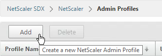
- In the Admin Profiles pane, click Add.
- In the Create Admin Profile dialog box, set the following parameters:
- Profile Name*—Name of the admin profile. The default profile name is nsroot. You can create user-defined profile names.
- User Name—User name used to log on to the NetScaler instances. The user name of the default profile is nsroot and cannot be changed.
- Password*—The password used to log on to the NetScaler instance. Maximum length: 31 characters.
- Confirm Password*—The password used to log on to the NetScaler instance.
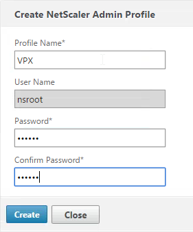
- Click Create. The admin profile you created appears in the Admin Profiles pane.
To upload a NetScaler VPX .xva file
You must upload a NetScaler VPX .xva file to the SDX appliance before provisioning the NetScaler VPX instances.
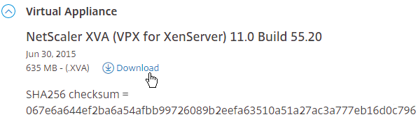
- Download the Virtual Appliance XVA from the SDX Software Bundle Download Page.
- On the Configuration tab, in the navigation pane, expand NetScaler Configuration, and then click Software Images.
- On the right, switch to the XVA Files tab and then click Upload.
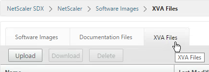
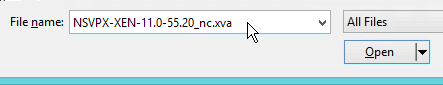
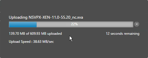
- In the Upload NetScaler Instance XVA dialog box, click Browse and select the XVA image file that you want to upload. Click Upload. The XVA image file appears in the NetScaler XVA Files pane after it is uploaded.
To provision a NetScaler instance
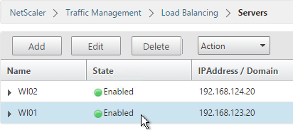
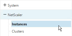
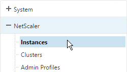
- On the Configuration tab, in the navigation pane, expand NetScaler Configuration, and then click Instances.
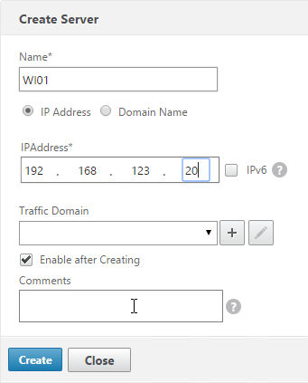
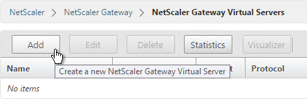
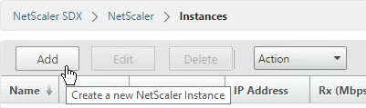
- In the NetScaler Instances pane, click Add.
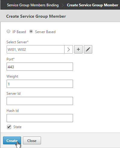
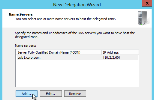
- In the Provision NetScaler Wizard follow the instructions in the wizard.
- Click Create. The NetScaler instance you provisioned appears in the NetScaler Instances pane.
The wizard will ask for the following info:
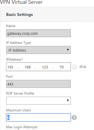
- Name* – The host name assigned to the NetScaler instance.
- IP Address* – The NetScaler IP (NSIP) address at which you access a NetScaler instance for management purposes. A NetScaler instance can have only one NSIP. You cannot remove an NSIP address.
- Netmask* – The subnet mask associated with the NSIP address.
- Gateway* – The default gateway that you must add on the NetScaler instance if you want access through SSH or the configuration utility from an administrative workstation or laptop that is on a different network.
- Nexthop to Management Service (11.0 build 64 and newer) – Adds a static route on the NSIP network so SDX Management Service can communicate with the instance NSIP. Only needed if instance default gateway and instance NSIP are on separate networks. 💡
- XVA File* – The .xva image file that you need to provision. This file is required only when you add a NetScaler instance.
- Feature License* – Specifies the license you have procured for the NetScaler. The license could be Standard, Enterprise, and Platinum.
- Admin Profile* – The profile you want to attach to the NetScaler instance. This profile specifies the user credentials that are used by the Management Service to provision the NetScaler instance and later, to communicate with the instance to retrieve configuration data. The user credentials used in this profile are also used while logging on to the NetScaler instance by using the GUI or the CLI. It is recommended that you change the default password of the admin profile. This is done by creating a new profile with a user-defined password. For more information, see Configuring Admin Profiles.
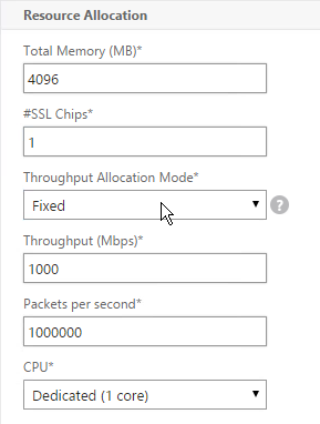
- Total Memory (MB)* – The total memory allocated to the NetScaler instance.
- #SSL Cores* – Number of SSL cores assigned to the NetScaler instance. SSL cores cannot be shared. The instance is restarted if you modify this value.
- Throughput (Mbps)* – The total throughput allocated to the NetScaler instance. The total used throughput should be less than or equal to the maximum throughput allocated in the SDX license. If the administrator has already allocated full throughput to multiple instances, no further throughput can be assigned to any new instance.
- Packets per second* – The total number of packets received on the interface every second.
- CPU – Assign a dedicated core or cores to the instance or the instance shares a core with other instance(s).
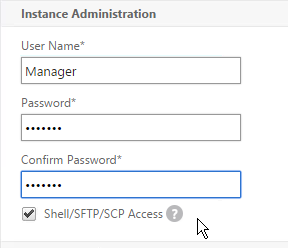
- User Name* – The root user name for the NetScaler instance administrator. This user has superuser access, but does not have access to networking commands to configure VLANs and interfaces. (List of non-accessible commands will be listed here in later versions of this document)
- Password* – The password for the root user.
- Shell/Sftp/Scp Access* – The access allowed to the NetScaler instance administrator.
- Interface Settings – This specifies the network interfaces assigned to a NetScaler instance. You can assign interfaces to an instance. For each interface, if you select Tagged, specify a VLAN ID.
- Important:The interface ID numbers of interfaces that you add to an instance do not necessarily correspond to the physical interface numbering on the SDX appliance. For example, if the first interface that you associate with instance 1 is SDX interface 1/4, it appears as interface 1/1 when you log on to the instance and view the interface settings, because it is the first interface that you associated with instance 1.
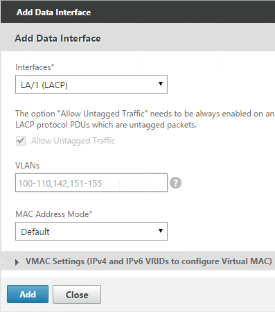
- If a non-zero VLAN ID is specified for a NetScaler instance interface, all the packets transmitted from the NetScaler instance through that interface will be tagged with the specified VLAN ID. If you want incoming packets meant for the NetScaler instance that you are configuring to be forwarded to the instance through a particular interface, you must tag that interface with the VLAN ID you want and ensure that the incoming packets specify the same VLAN ID.
- For an interface to receive packets with several VLAN tags, you must specify a VLAN ID of 0 for the interface, and you must specify the required VLAN IDs for the NetScaler instance interface.
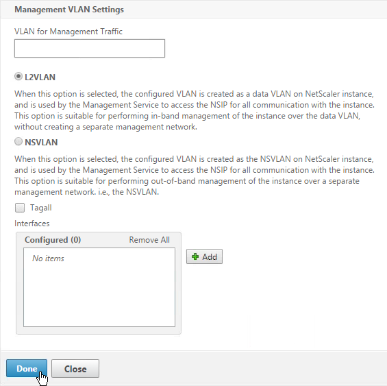
- NSVLAN ID – An integer that uniquely identifies the NSVLAN. Minimum value: 2. Maximum value: 4095.
- Tagged – Designate all interfaces associated with the NSVLAN as 802.1q tagged interfaces.
- Interfaces – Bind the selected interfaces to the NSVLAN.
Here are screenshots from the wizard:
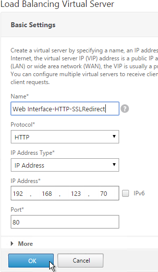
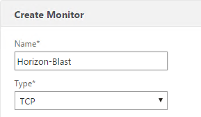
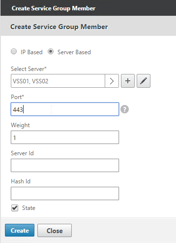
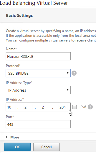
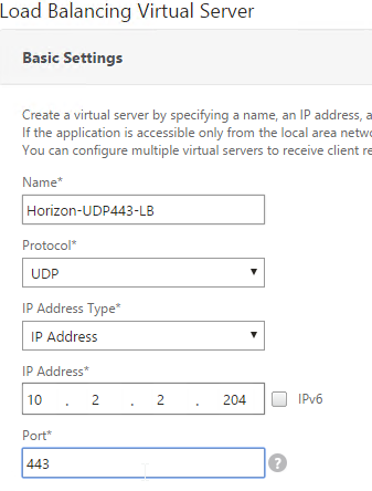
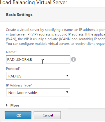
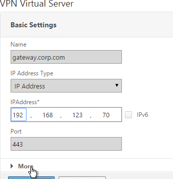
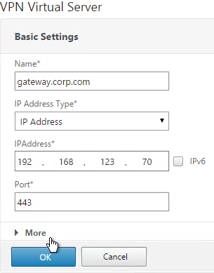
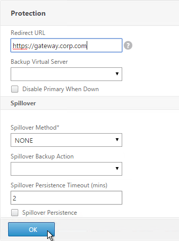
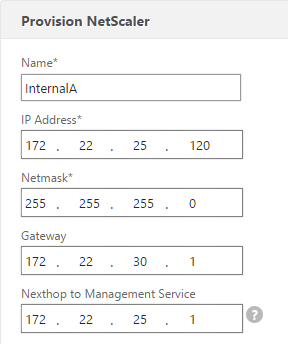
- In the Provision NetScaler section, enter a name for the instance.
- Enter the NSIP, mask, and Gateway.
- Nexthop to Management Service is new in 11.0 build 64 and newer. If the default gateway is on a different network than the NSIP, then enter a next hop router address on the NSIP network so the SDX Management Service can communicate with the NSIP. 💡
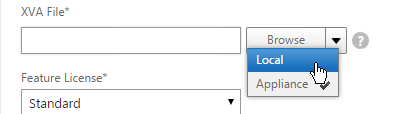
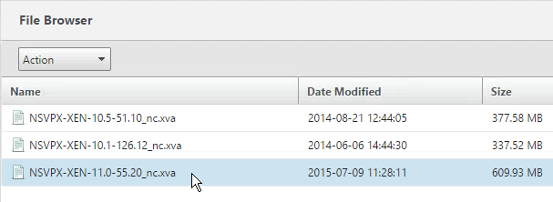
- In the XVA File field, you can Browse > Local to select an XVA file on your file system. Or you can Browse > Appliance and select an XVA file that has already been uploaded.
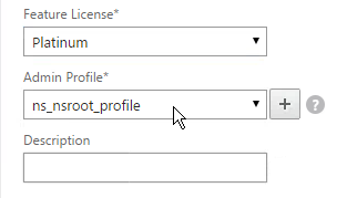
- Change the Feature License to Platinum.
- Select an Admin Profile created earlier.
- Enter a Description. Scroll down.
- In the Resource Allocation section, change the Total Memory to 4096.
- For SSL Chips, specify between 1 and 16.
- For Throughput, partition your licensed bandwidth. If you are licensed for 8 Gbps, make sure the total of all VPX instances does not exceed that number.
- Burstable is also an option. Fixed bandwidth can’t be shared with other instances. Burstable can be shared. See Bandwidth Metering in NetScaler SDX at docs.citrix.com
- For CPU, select one of the Dedicated options. Then scroll down.
- In the Instance Administration section, enter a new local account that will be created on the VPX. This is in addition to the nsroot user. Note, not all functionality is available to this account. Scroll down.
- In the Network Settings section, leave 0/1 selected and deselect 0/2.
- Click Add to connect the VPX to more interfaces.
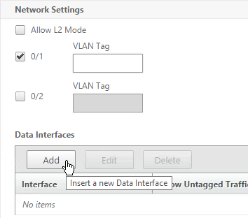
- If you have Port Channels, select one of the LA interfaces.
- Try not configure any VLAN settings here. If you do, XenServer filters the VLANs available to the VPX instance. Changing the VLAN filtering settings later probably requires a reboot. Click Add.
- In the Management VLAN Settings section, do not configure anything in this section unless you need to tag the NSIP VLAN. Click Done.
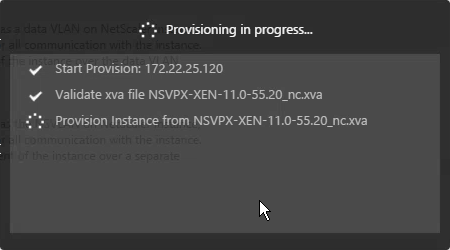
- After a couple minutes the instance will be created. Click Close.
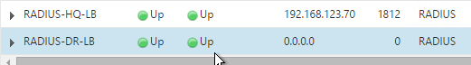
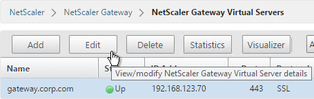
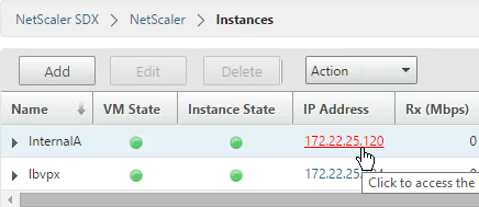
- In your Instances list, click the IP address to launch the VPX management console. Do the following at a minimum (instructions in the NetScaler System Configuration page):
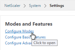
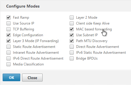
- Enable MAC Based Forwarding – System > Settings > Configure Modes > MAC Based Forwarding
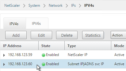
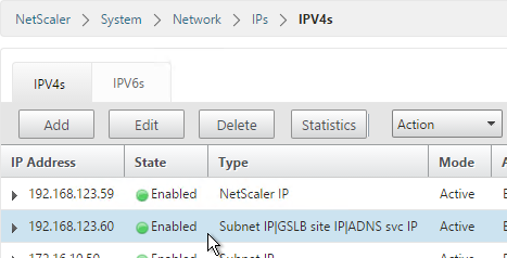
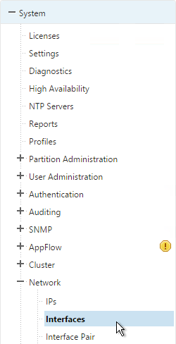
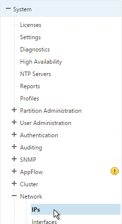
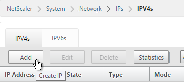
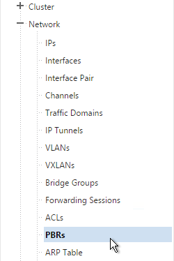
- Add SNIPs for each VLAN – System > Network > IPs
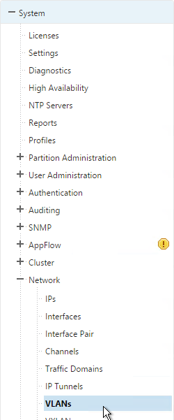
- Add VLANs and bind to SNIPs – System > Network > VLANs
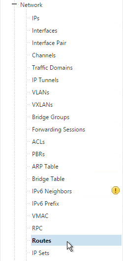
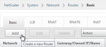
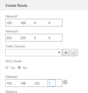
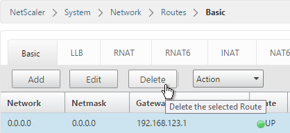
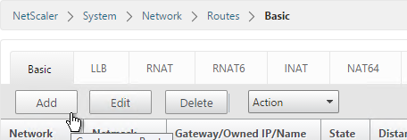
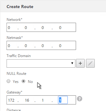
- Change default gateway – System > Network > Routes > 0.0.0.0
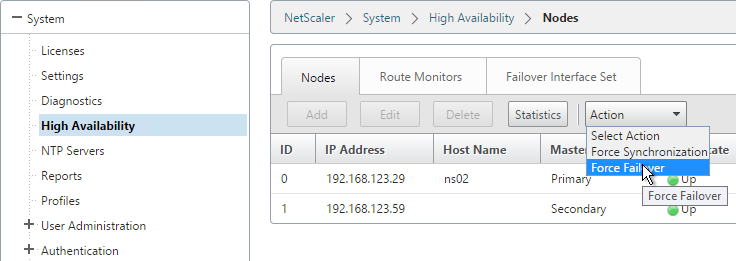
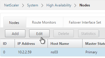
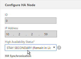
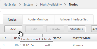
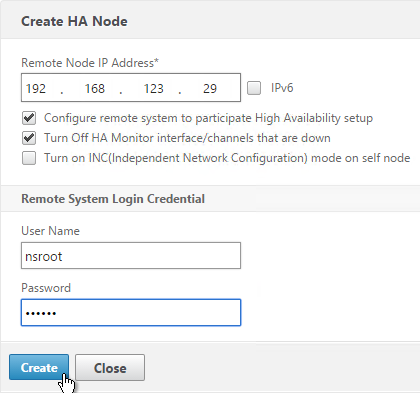
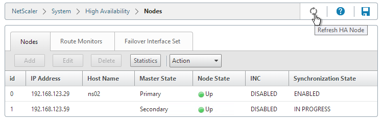
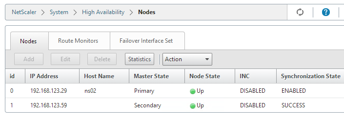
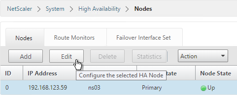
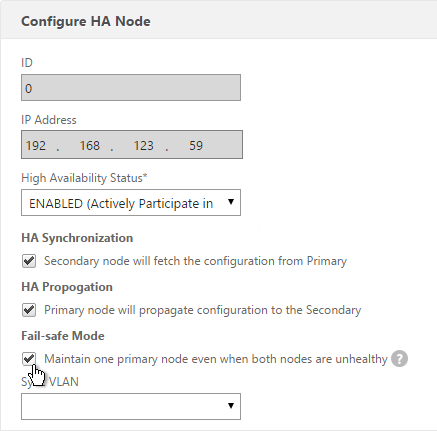
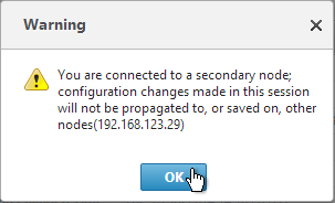
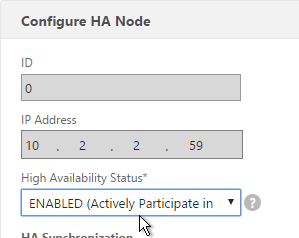
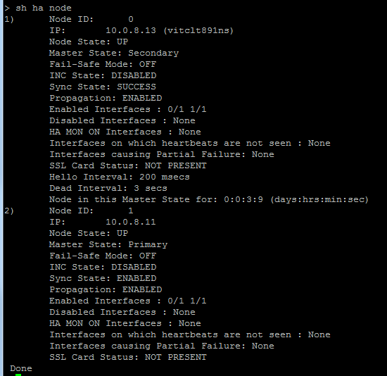
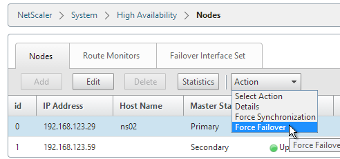
- Create another instance on a different SDX and High Availability pair them together – System > High Availability
Applying the Administration Configuration
At the time of provisioning a NetScaler VPX instance, the Management Service creates some policies, instance administration (admin) profile, and other configuration on the VPX instance. If the Management Service fails to apply the admin configuration at this time due to any reason (for example, the Management Service and the NetScaler VPX instance are on different subnetworks and the router is down or if the Management Service and NetScaler VPX instance are on the same subnet but traffic has to pass through an external switch and one of the required links is down), you can explicitly push the admin configuration from the Management Service to the NetScaler VPX instance at any time.
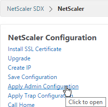
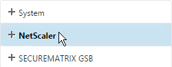
- On the Configuration tab, in the navigation pane, click NetScaler.
- In the NetScaler Configuration pane, click Apply Admin Configuration.
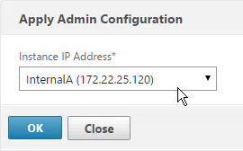
- In the Apply Admin Configuration dialog box, in Instance IP Address, select the IP address of the NetScaler VPX instance on which you want to apply the admin configuration.
- Click OK.
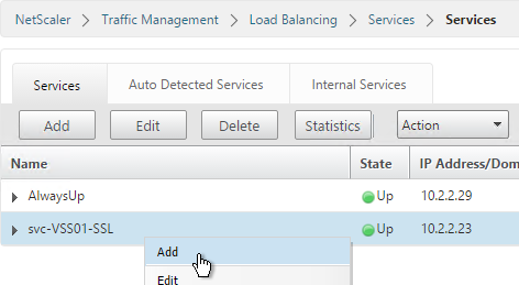
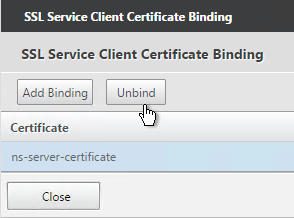
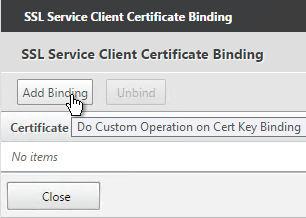
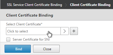
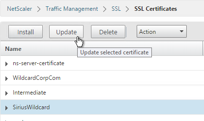
VPX Instances – Manage
You may login to the VPX instance and configure everything normally. SDX also offers the ability to manage IP address and SSL certificates from SDX rather than from inside the VPX instance. The SDX Management Service does not have the ability to create certificates so it’s probably best to do that from within the VPX instance.
To view the console of a NetScaler instance
- Connect to the Management Service using https.
- Viewing the console might not work unless you replace the Management Service certificate.
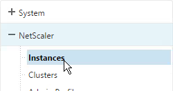
- In the Management Service, go to Configuration > NetScaler > Instances.
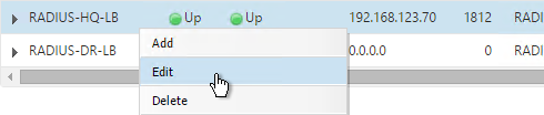
- On the right, right-click an instance and click Console.
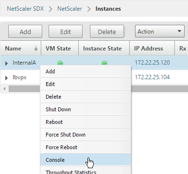
- The instance console then appears.
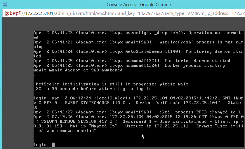
- Another option is to use the Lights Out Module and the xl console command as detailed at Citrix Blog Post SDX Remote Console Access of VIs.
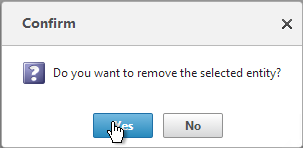
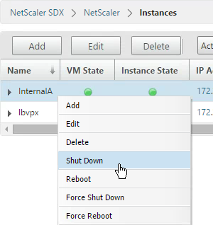
To start, stop, delete, or restart a NetScaler instance
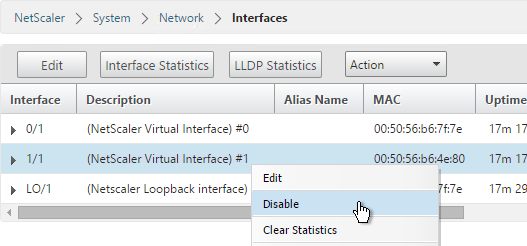
- On the Configuration tab, in the navigation pane, expand NetScaler and click Instances.
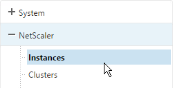
- In the Instances pane, right-click the NetScaler instance on which you want to perform the operation, and then click Start or Shut Down or Delete or Reboot.
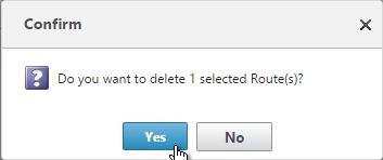
- In the Confirm message box, click Yes.
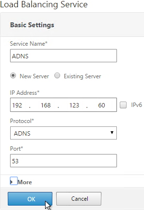
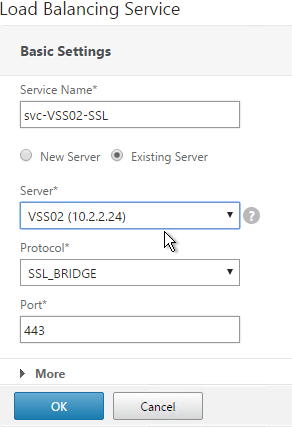
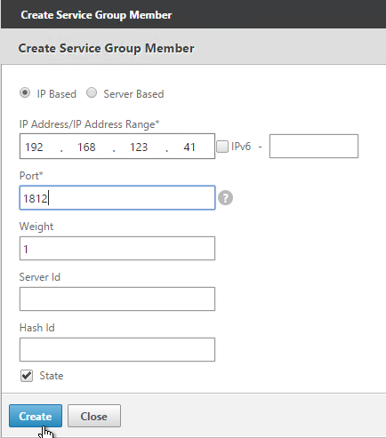
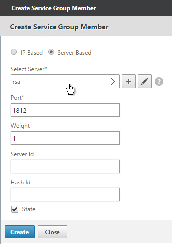
Creating a Subnet IP Address on a NetScaler Instance
You can create or delete a SNIP during runtime without restarting the NetScaler instance.
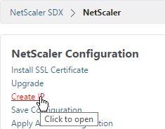
- On the Configuration tab, in the navigation pane, click NetScaler.
- In the NetScaler Configuration pane, click Create IP.
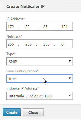
- In the Create NetScaler IP dialog box, specify values for the following parameters.
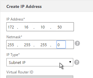
- IP Address* – Specify the IP address assigned as the SNIP or the MIP address.
- Netmask* – Specify the subnet mask associated with the SNIP or MIP address.
- Type* – Specify the type of IP address. Possible values: SNIP.
- Save Configuration* – Specify whether the configuration should be saved on the NetScaler. Default value is false.
- Instance IP Address* – Specify the IP address of the NetScaler instance.
- Click Create.
Create a VLAN on a NetScaler instance
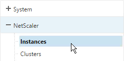
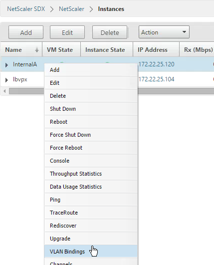
- Go to NetScaler > Instances.
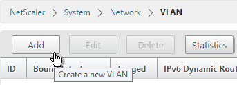
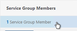
- Right-click an instance and click VLAN Bindings.
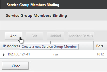
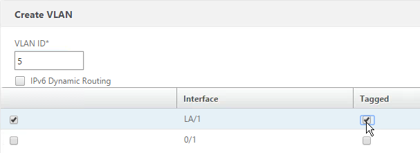
- Click Add.
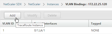
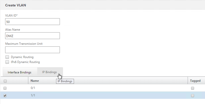
- Enter a VLAN ID and select an interface.
- Check the box for Tagged if needed.
- Notice there’s no way to bind a SNIP. You do that inside the instance. Click Create.
To save the configuration on a NetScaler instance
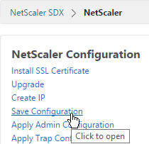
- On the Configuration tab, in the navigation pane, click NetScaler.
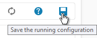
- In the NetScaler pane, click Save Configuration.
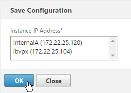
- In the Save Configuration dialog box, in Instance IP Address, select the IP addresses of the NetScaler instances whose configuration you want to save.
- Click OK.
Change NSIP of VPX Instance
If you change NSIP inside of VPX instead of using the Modify Instance wizard in the Service VM, see article http://support.citrix.com/article/CTX139206 to adjust the XenServer settings.
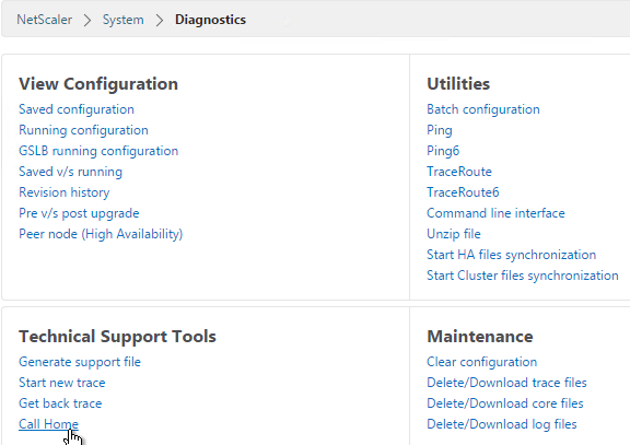
Enable Call Home
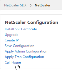
- On the Configuration tab, in the navigation pane, click the NetScaler node.
- On the right, click Call Home.
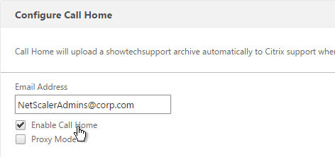
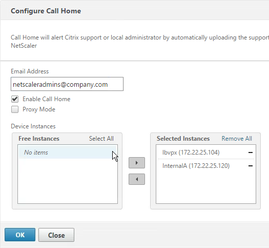
- Enter an email address to receive communications regarding NetScaler Call Home.
- Check the box next to Enable Call Home.
- Select the instances to enable Call Home and click OK.
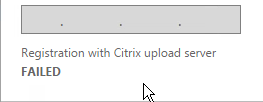
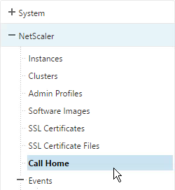
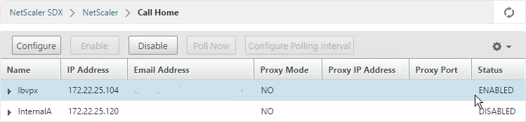
- You can view the status of Call Home by expanding NetScaler and clicking Call Home.
- The right pane indicates if it’s enabled or not. You can also configure Call Home from here.
VPX Instance – Firmware Upgrade
Upload NetScaler Firmware Build Files
To upgrade a VPX instance from the Management Service, first upload the firmware build file.
- Download the NetScaler firmware using the normal method.
- In the Configuration tab, on the left, expand NetScaler and click Software Images.
- On the right, in the Software Images tab click Upload.
- Browse to the build…tgz file and click Open.
Upgrading Multiple NetScaler VPX Instances
You can upgrade multiple instances at the same time.
- To prevent any loss of the configuration running on the instance that you want to upgrade, save the configuration on the instance before you upgrade the instance.
- On the Configuration tab, in the navigation pane, expand NetScaler and click Instances.
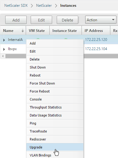
- Right-click an instance and click Upgrade.
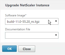
- In the Upgrade NetScaler dialog box, in Build File, select the NetScaler upgrade build file of the version you want to upgrade to. Ignore the Documentation File. Click OK.
Management Service Monitoring
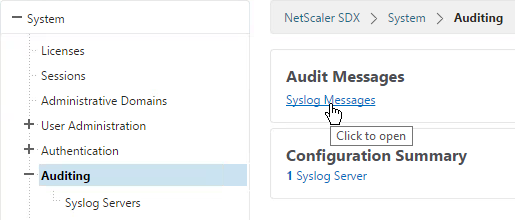
- To view syslog, in the navigation pane, expand System, click Auditing and then click Syslog Message in the right pane.
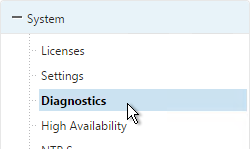
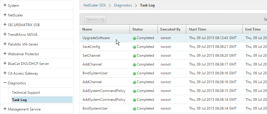
- To view the task log, in the navigation pane, expand Diagnostics, and then click Task Log.
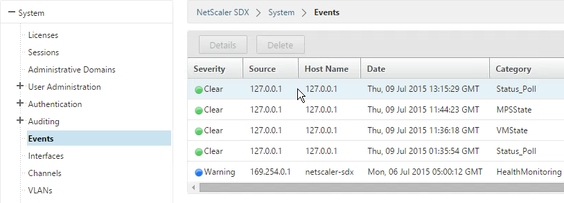
- To view Management Service events, on the Configuration tab, in the expand System and click Events.
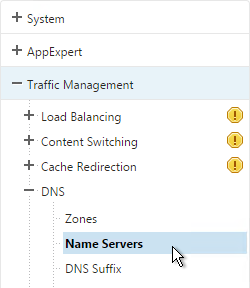
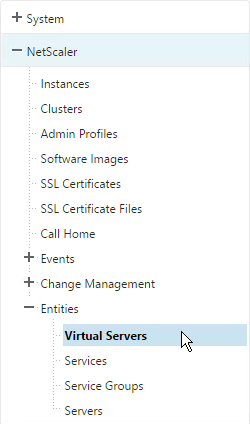
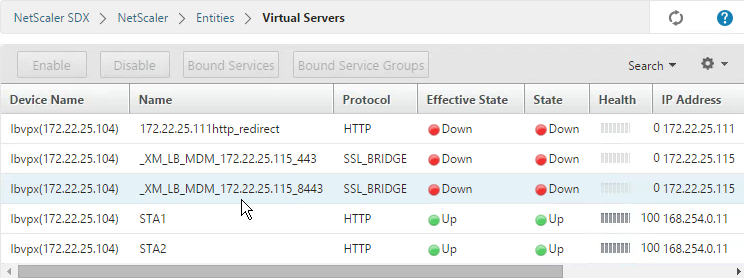
- NetScaler > Entities lets you see the various Load Balancing entities configured on the instances.
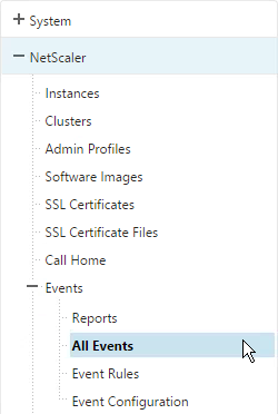
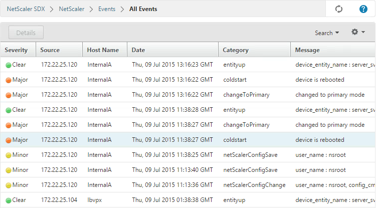
- To view instance alerts, go to NetScaler > Events > All Events.
- There is also event reporting.
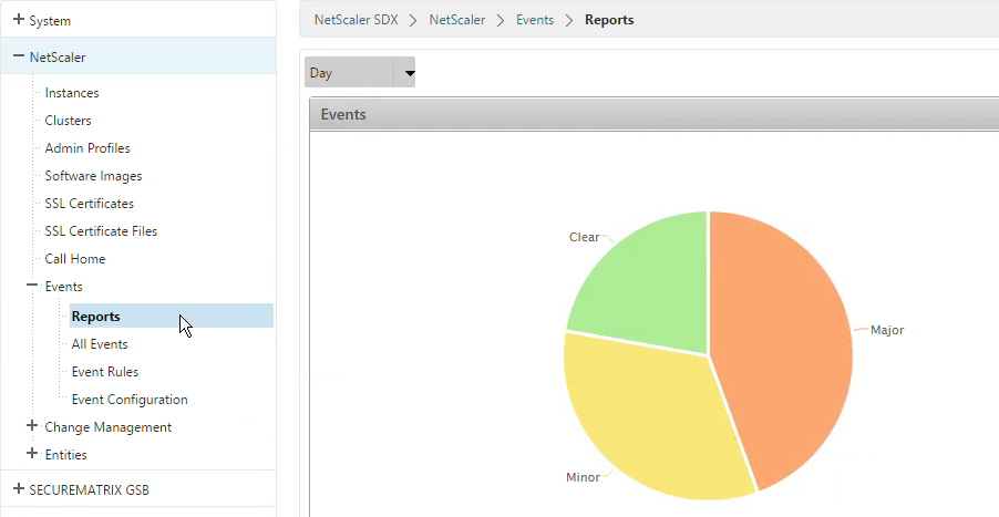
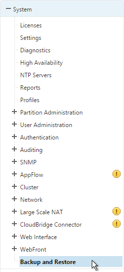
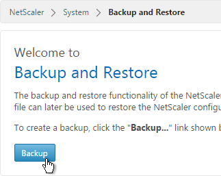
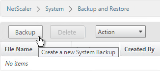
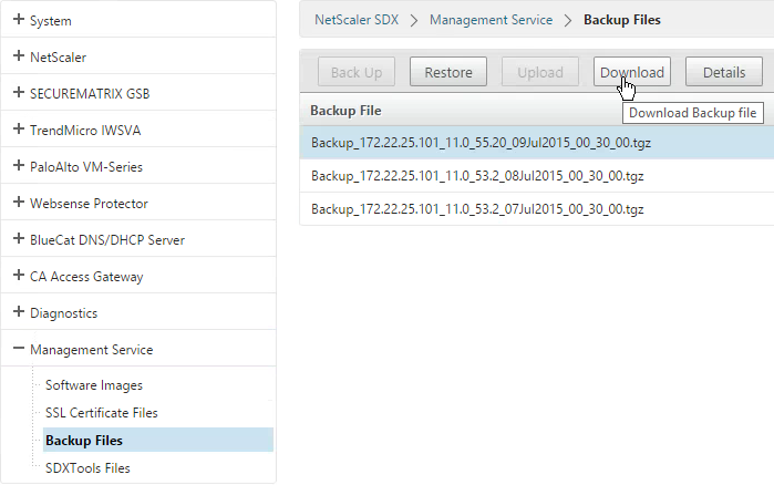
Management Service Backups
The SDX appliance automatically keeps three backups of the Service VM configuration that are taken daily at 12:30 am.
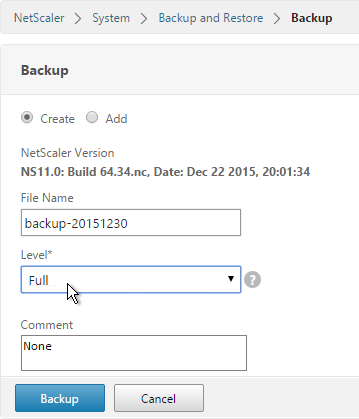
Backups in NetScaler SDX 11.0 contain the following:
- Single bundle image
- NetScaler XVA image
- NetScaler upgrade image
- Management Service image
- Management Service configuration
- NetScaler SDX configuration
- NetScaler configuration
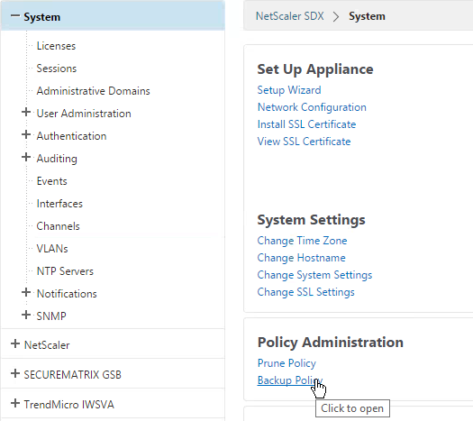
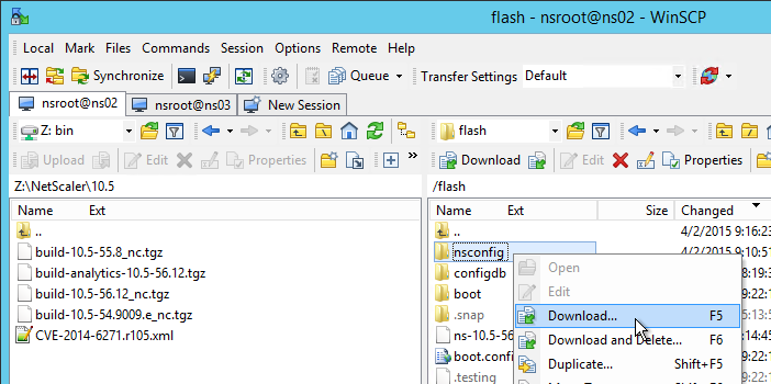
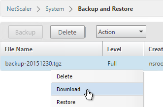
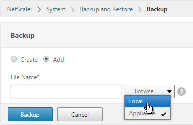
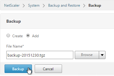
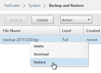
You can go to Management Service > Backup Files to backup or restore the appliance’s configuration. And you can download the backup files.
You can configure the number of retained backups by clicking System on the left and then clicking Backup Policy in the right pane.